EP2541733A1 - Terminal sans fil portable, dispositif formant terminal sans fil et système de transmission sans fil - Google Patents
Terminal sans fil portable, dispositif formant terminal sans fil et système de transmission sans fil Download PDFInfo
- Publication number
- EP2541733A1 EP2541733A1 EP11747509A EP11747509A EP2541733A1 EP 2541733 A1 EP2541733 A1 EP 2541733A1 EP 11747509 A EP11747509 A EP 11747509A EP 11747509 A EP11747509 A EP 11747509A EP 2541733 A1 EP2541733 A1 EP 2541733A1
- Authority
- EP
- European Patent Office
- Prior art keywords
- wireless
- wireless terminal
- communication
- terminal
- terminal device
- Prior art date
- Legal status (The legal status is an assumption and is not a legal conclusion. Google has not performed a legal analysis and makes no representation as to the accuracy of the status listed.)
- Granted
Links
Images


Classifications
-
- H—ELECTRICITY
- H02—GENERATION; CONVERSION OR DISTRIBUTION OF ELECTRIC POWER
- H02J—ELECTRIC POWER NETWORKS; CIRCUIT ARRANGEMENTS OR SYSTEMS FOR SUPPLYING OR DISTRIBUTING ELECTRIC POWER; SYSTEMS FOR STORING ELECTRIC ENERGY
- H02J50/00—Circuit arrangements or systems for wireless supply or distribution of electric power
- H02J50/005—Mechanical details of housing or structure aiming to accommodate the power transfer means, e.g. mechanical integration of coils, antennas or transducers into emitting or receiving devices
-
- H—ELECTRICITY
- H02—GENERATION; CONVERSION OR DISTRIBUTION OF ELECTRIC POWER
- H02J—ELECTRIC POWER NETWORKS; CIRCUIT ARRANGEMENTS OR SYSTEMS FOR SUPPLYING OR DISTRIBUTING ELECTRIC POWER; SYSTEMS FOR STORING ELECTRIC ENERGY
- H02J50/00—Circuit arrangements or systems for wireless supply or distribution of electric power
- H02J50/10—Circuit arrangements or systems for wireless supply or distribution of electric power using inductive coupling
-
- H—ELECTRICITY
- H02—GENERATION; CONVERSION OR DISTRIBUTION OF ELECTRIC POWER
- H02J—ELECTRIC POWER NETWORKS; CIRCUIT ARRANGEMENTS OR SYSTEMS FOR SUPPLYING OR DISTRIBUTING ELECTRIC POWER; SYSTEMS FOR STORING ELECTRIC ENERGY
- H02J50/00—Circuit arrangements or systems for wireless supply or distribution of electric power
- H02J50/40—Circuit arrangements or systems for wireless supply or distribution of electric power using two or more transmitting or receiving devices
-
- H—ELECTRICITY
- H02—GENERATION; CONVERSION OR DISTRIBUTION OF ELECTRIC POWER
- H02J—ELECTRIC POWER NETWORKS; CIRCUIT ARRANGEMENTS OR SYSTEMS FOR SUPPLYING OR DISTRIBUTING ELECTRIC POWER; SYSTEMS FOR STORING ELECTRIC ENERGY
- H02J50/00—Circuit arrangements or systems for wireless supply or distribution of electric power
- H02J50/80—Circuit arrangements or systems for wireless supply or distribution of electric power involving the exchange of data, concerning supply or distribution of electric power, between transmitting devices and receiving devices
-
- H—ELECTRICITY
- H02—GENERATION; CONVERSION OR DISTRIBUTION OF ELECTRIC POWER
- H02J—ELECTRIC POWER NETWORKS; CIRCUIT ARRANGEMENTS OR SYSTEMS FOR SUPPLYING OR DISTRIBUTING ELECTRIC POWER; SYSTEMS FOR STORING ELECTRIC ENERGY
- H02J7/00—Circuit arrangements for charging or discharging batteries or for supplying loads from batteries
- H02J7/40—Circuit arrangements for charging or discharging batteries or for supplying loads from batteries characterised by the exchange of charge or discharge related data
- H02J7/42—Circuit arrangements for charging or discharging batteries or for supplying loads from batteries characterised by the exchange of charge or discharge related data with electronic devices having internal batteries, e.g. mobile phones
-
- H—ELECTRICITY
- H02—GENERATION; CONVERSION OR DISTRIBUTION OF ELECTRIC POWER
- H02J—ELECTRIC POWER NETWORKS; CIRCUIT ARRANGEMENTS OR SYSTEMS FOR SUPPLYING OR DISTRIBUTING ELECTRIC POWER; SYSTEMS FOR STORING ELECTRIC ENERGY
- H02J7/00—Circuit arrangements for charging or discharging batteries or for supplying loads from batteries
- H02J7/70—Circuit arrangements for charging or discharging batteries or for supplying loads from batteries characterised by the mechanical construction
- H02J7/731—Circuit arrangements for charging or discharging batteries or for supplying loads from batteries characterised by the mechanical construction specially adapted for holding portable devices containing batteries
Definitions
- the present invention relates to a portable wireless terminal, a wireless terminal device, and a wireless communication system.
- Priority is claimed on Japanese Patent Application No. 2010-40096, filed on February 25, 2010 , the content of which is incorporated herein by reference.
- transceivers In recent years, spread and development of wireless communication techniques such as wireless LAN (Local Area Network) allow transceivers to be provided with a wireless communication function at a low cost. As a result, pairs of transceivers are more often introduced to general households and corporate facilities, and communication settings are made for the transceivers to conduct wireless communication (for example, settings of ID (identification data) and exchange of cryptographic keys). Furthermore, transceivers are required to further include an application such as frequently changing targets of wireless communication.
- wireless LAN Local Area Network
- a secondary battery reusable by recharging such as a Ni-Cd (nickel cadmium) battery or a lithium battery is more often used.
- a recharging system utilizing contactless power transmission is established, which utilizes electromagnetic induction or the like to eliminate the necessity of using electric contact.
- Such a recharging system utilizing contactless power transmission has come into wide use mainly for the products used in damp or wet locations where it is not favorable to use electric contacts.
- an applied technique of contactless power transmission there is disclosed a technique of superimposing data transmission signals on a contactless power transmission channel (for example, see Patent Document 1).
- the contactless power transmission path transmits data at a frequency lower than that used as a carrier frequency of high-speed data transmission (several hundred MHz or higher). Accordingly, it is difficult to improve the data transfer the data transfer rate of the contactless power transfer path. Therefore, the contactless power transmission path is not good to be used for transmitting large volumes of image data and the like in a short period of time.
- the present invention has been achieved in view of the above problems, and has an object to provide a portable wireless terminal, wireless terminal device and a wireless communication system that allow for facilitating communication settings for wireless communication.
- the present invention is a portable wireless terminal, including: a battery portion that accumulates electric power; a terminal wireless data communication portion that wirelessly communicates information; a terminal communication setting portion that sets predetermined setting information related to wireless communication by the terminal wireless data communication portion; and a power reception antenna that receives electric power for recharging the battery portion in a contactless manner from an external terminal, the power reception antenna transmitting or receiving the setting information to or from the external terminal.
- the power reception antenna transmit or receive, as the setting information, information necessary at a beginning of the wireless communication by the terminal wireless data communication portion.
- the setting information be a user identification data or ciphering data for the wireless communication.
- the power reception antenna transmit or receive the setting information during the recharging or the electric power reception.
- the present invention is a portable terminal device including: a wireless data communication portion that wirelessly communicates information; a communication setting portion that sets predetermined setting information related to wireless communication by the wireless data communication portion; and a power transmission antenna that transmits electric power in a contactless manner to an external terminal, the power transmission antenna transmitting or receiving the setting information to or from the external terminal.
- the power transmission antenna and the wireless data communication portion be arranged in separate housings.
- the present invention is a wireless communication system including: a portable wireless terminal and a wireless terminal device, wherein the portable wireless terminal includes: a battery portion that accumulates electric power; a terminal wireless data communication portion that wirelessly communicates information; a terminal communication setting portion that sets predetermined setting information related to wireless communication by the terminal wireless data communication portion; and a power reception antenna that receives electric power for recharging the battery portion in a contactless manner from the wireless terminal device, the power reception antenna transmitting or receiving the setting information to or from the wireless terminal device, and wherein the wireless terminal device comprises: a wireless data communication portion that wirelessly communicates information; a communication setting portion that sets predetermined setting information related to wireless communication by the wireless data communication portion; and a power transmission antenna that transmits electric power in a contactless manner to the portable wireless terminal, the power transmission antenna transmitting or receiving the setting information to or from the portable wireless terminal.
- the terminal communication setting portion limit the wireless terminal device with which the terminal wireless data communication portion wirelessly communicates to the wireless terminal device to or from which the power reception antenna transmits or receives the setting information.
- the communication setting portion limit the portable wireless terminal with which the wireless data communication portion wirelessly communicates to the portable wireless terminal to or from which the power transmission antenna transmits or receives the setting information.
- a coverage distance of a wireless communication line between the power transmission antenna and the power reception antenna be substantially equal to a distance that electric power is allowed to be transmitted in the contactless manner.
- the power reception antenna that receives electric power for recharging the battery portion in a contactless manner from an external terminal receives or transmits predetermined setting information related to wireless communication by the terminal wireless data communication portion. Therefore, it is possible to make communication settings for conducting wireless communication without troublesome inputs to a wireless instrument.
- FIG. 1 is a block diagram showing a schematic configuration of a wireless communication system of the present embodiment.
- the wireless communication system includes: a wireless terminal device 10; and a portable wireless terminal 20.
- the wireless terminal device 10 includes: a main unit portion 11; and a contactless power transmission portion 102.
- the main unit portion 11 includes: a power source portion 101; a storage portion 103; a communication setting portion 104; and a high-speed wireless communication portion 105 (wireless data communication portion).
- the contactless power transmission portion 102 includes a coil antenna 1021 (power transmission antenna).
- the portable wireless terminal 20 includes: a contactless power reception portion 201; a battery 202; a terminal communication setting portion 203; a terminal storage portion 204; and a terminal high-speed wireless communication portion 205 (terminal wireless data communication portion).
- the contactless power reception portion 201 includes a coil antenna 2011 (power reception antenna).
- the power source portion 101 is connected to a commercial AC power source.
- the power source portion 101 supplies the electric power, which is supplied from the commercial power source, to the respective portions included in the wireless terminal device 10.
- the contactless power transmission portion 102 modifies the electric power, which is supplied from the power source portion 101, so as to be efficiently received by the contactless power reception portion 201 of the portable wireless terminal 20, and transmits the modified electric power via the coil antenna 1021.
- the contactless power transmission portion 102 uses a second wireless communication line to communicate with the contactless power reception portion 201 of the portable wireless terminal 20 via the coil antenna 1021.
- the second wireless communication line will be described in detail later.
- the storage portion 103 stores information necessary for conducting communication by use of a first wireless communication line.
- the first wireless communication line will be described in detail later.
- the communication setting portion 104 makes communication settings of the first wireless communication line.
- the high-speed wireless communication portion 105 uses the first wireless communication line to communicate with the terminal high-speed wireless communication portion 205 of the portable wireless terminal 20.
- the contactless power reception portion 201 converts the electric power, which has been received from the contactless power transmission portion 102 via the coil antenna 2011, to direct-current electric power to recharge the battery 202.
- the contactless power reception portion 201 uses the second wireless communication line to communicate with the contactless power transmission portion 102 of the wireless terminal device 10 via the coil antenna 2011.
- the battery 202 is a secondary battery, which supplies electric power to the respective portions included in the portable wireless terminal 20.
- the terminal communication setting portion 203 makes communication settings of the first wireless communication line.
- the terminal storage portion 204 stores information necessary for conducting communication by use of the first wireless communication line.
- the terminal high-speed wireless communication portion 205 uses the first wireless communication line to communicate with the high-speed wireless communication portion 105 of the wireless terminal device 10.
- the main unit portion 11 and the contactless power transmission portion 102 are in separate housings by way of representative example. However, they may be integrated.
- the contactless power transmission portion 102 preferably has a shape of a cradle where, when the portable wireless terminal 20 is placed on the contactless power transmission portion 102, the coil antenna 1021 of the contactless power transmission portion 102 and the coil antenna 2011 of the contactless power reception portion 201 are set in a positional relationship favorable for contactless power transmission.
- the wireless terminal device 10 is supposed to have a well-developed GUI (Graphical User Interface) as is the case with personal computers.
- the portable wireless terminal 20 is supposed to have difficulty inputting letters and characters as is the case with digital cameras.
- the case where the personal computer communicates with the digital camera is a known case.
- the first wireless communication line is a high-speed data communication line represented by a wireless LAN standardized as IEEE 802.11a/b/g or the like.
- the high-speed wireless communication portion 105 of the wireless terminal device 10 and the terminal high-speed wireless communication portion 205 of the portable wireless terminal 20 use the first wireless communication line to communicate with each other.
- the first wireless communication line typically has a coverage distance of several meters to tens of meters. Within that range, the first wireless communication line enables data exchange at high speeds.
- the first wireless communication line is not limited to one on a standardized communication system but may be one on an original wireless system.
- the communication setting portion 104 and the terminal communication setting portion 203 make communication settings by exchanging information such as a group ID or a cryptographic key.
- the communication settings include a setting such as specifying a communication target. They are typical settings necessary for conducting communication by use of a wireless LAN or the like.
- the group ID is a piece of information that is capable of uniquely specifying a group to which the wireless terminal device 10 and the portable wireless terminal 20 belong.
- the second wireless communication line is a wireless communication line for which a technique of superimposing data transmission signals on a contactless power transmission channel is used. Therefore, the coil antenna 2011 of the contactless power reception portion 201 is capable of transmitting or receiving the setting information while receiving the electric power from the coil antenna 1021 of the contactless power transmission portion 102 or recharging the battery 202.
- the distance within which the second wireless communication line can communicate (the distance that the data signal can reach) is substantially the same as the distance that the electric power can be transmitted in a contactless manner.
- the communication offers high data confidentiality. Furthermore, it is possible to transmit/receive data without making communication settings such as a setting of communication targets. Therefore, if the contactless power transmission portion 102 of the wireless terminal device 10 and the contactless power reception portion 201 of the portable wireless terminal 20 are closer than the transmission distance of the second wireless communication line, it is possible to conduct communication by use of the second wireless communication line without making communication settings.
- the frequency used as a carrier frequency for the data transmission by use of the second wireless communication line is lower than that used as a carrier frequency for the high-speed data transmission in recent years (several hundred MHz or higher). Therefore, the second wireless communication line has a low data transmission rate. Furthermore, because the transmission distance of the second wireless communication line is more favorable as it is shorter in view of keeping the data confidentiality, it is preferable to determine the transmission distance based on a tradeoff between usability and distance.
- the contactless power transmission portion 102 of the wireless terminal device 10 and the contactless power reception portion 201 of the portable wireless terminal 20 use the second wireless communication line to transmit/receive information, such as an ID and cryptographic key, which is necessary for conducting communication by use of the first wireless communication line.
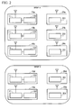
- FIG 2 is a schematic diagram showing a group to which the wireless terminal device 10 and the portable wireless terminal 20 included in the wireless communication system of the present embodiment belong.
- wireless terminal devices 10a to 10e and portable wireless terminals 20a to 20e are included in the wireless communication system.
- the wireless terminal devices 10a to 10c and the portable wireless terminals 20a to 20c belong to a group A.
- the wireless terminal devices 10d, 10e and the portable wireless terminals 20d, 20e belong to a group B.
- the wireless terminal devices 10a to 10c belonging to the group A and the portable wireless terminals 20d, 20e belonging to the group B be set so as not to be allowed to communicate with each other.
- the wireless terminal devices 10d, 10e belonging to the group B and the portable wireless terminals 20a to 20c belonging to the group A be set so as not to be allowed to communicate with each other.
- the system of communication setting for the high-speed wireless communication portion 105 of the wireless terminal device 10 and the terminal high-speed wireless communication portion 205 of the portable wireless terminal 20 to communicate with each other by use of the first wireless communication line is assumed to be a system in which the wireless terminal devices 10a to 10c and the portable wireless terminals 20a to 20c belonging to the group A, and the wireless terminal devices 10d, 10e and the portable wireless terminals 20d, 20e belonging to the group B are not allowed to communicate with each other unless they have a group ID and a cryptographic key that are common in each group.
- This communication setting is made by the communication setting portion 104 of the wireless terminal device 10 and the terminal communication setting portion 203 of the portable wireless terminal 20.
- the group ID and the cryptographic key that are previously stored in the storage portion 103 of the wireless terminal device 10 are transmitted to the portable wireless terminal 20 by the communication setting portion 104 by use of the second wireless communication line. It is assumed that a group ID and a cryptographic key are input to the wireless terminal device 10 by a known method and that the group ID and the cryptographic key having been input are stored in the storage portion 103.
- a simple method of inputting a group ID and a cryptographic key to the wireless terminal device 10 is a method in which the operator utilizes a keyboard, a mouse, or the like provided to the wireless terminal device 10 to input the optionally-determined group ID and cryptographic key.
- a procedure of transmitting the group ID and the cryptographic key from the wireless terminal device 10 to the portable wireless terminal 20 by use of the second wireless communication line is as follows.
- the operator brings the contactless power reception portion 201 of the wireless terminal device 10 close to the contactless power transmission portion 102 of the wireless terminal device 10.
- the communication setting portion 104 transmits the group ID and cryptographic key previously stored in the storage portion 103 to the contactless power reception portion 201 via the contactless power transmission portion 102.
- the contactless power reception portion 201 receives the transmitted group ID and cryptographic key, and inputs them to the terminal communication setting portion 203. Based on the group ID and cryptographic key that have been input, the terminal communication setting portion 203 makes communication settings of the first wireless communication line, and causes the terminal storage portion 204 to store the group ID and cryptographic key. With these communication settings, the wireless terminal device 10 and the portable wireless terminal 20 that store the same group ID and cryptographic key are allowed to communicate with each other by use of the first wireless communication line.
- the operator is capable of exchanging the group ID and cryptographic key between the wireless terminal device 10 and the portable wireless terminal 20 only by bringing the contactless power reception portion 201 of the portable wireless terminal 20 close to the contactless power transmission portion 102 of the wireless terminal device 10 such as when recharging by typical contactless power transmission. Furthermore, even if the GUI of the portable wireless terminal 20 is not sufficient, the operator is capable of inputting a group ID and a cryptographic key to the portable wireless terminal 20 in a very simplified manner.
- the operator is capable of exchanging the group ID and cryptographic key between a wireless terminal device 10 and a portable wireless terminal 20 that belong to the same group only by bringing the contactless power reception portion 201 of the portable wireless terminal 20 close to the contactless power transmission portion 102 of the wireless terminal device 10. Therefore, the operator is capable of making settings with ease so that only the wireless terminal devices 10 and portable wireless terminals 20 that belong to the same group are allowed to communicate with each other.
- the problem about data confidentiality of the group ID and cryptographic key can be solved by the fact that the communication distance of the second wireless communication line is short. Namely, because the communication distance of the second wireless communication line is short, it is easy to prevent outsiders with malice from coming close to the contactless power transmission portion 102 of the wireless terminal device 10. Because the outsiders, who are prevented from coming close to the contactless power transmission portion 102, are not capable of transmitting the group ID and the cryptographic key to the portable wireless terminal 20, the data confidentiality of the group ID and the cryptographic key is protected. Furthermore, if a verification screen for transferring the group ID and the cryptographic key is provided in the wireless terminal device 10 and an input of a password or the like is prompted, then the confidentiality can be further enhanced.
- the group ID and cryptographic key are exchanged by use of the second wireless communication line.
- the information transmitted/received by use of the second wireless communication line is not limited to this.
- the information such as for enhancing the data confidentiality may be transmitted by use of the second wireless communication line.
- the transmission of the main information transmitted/received by use of the first wireless communication line is limited within a group. However, this does not deny any communication at all with another group. Controlling communication such as for avoiding collision is conducted also with instruments belonging to another group.
- the wireless terminal device 10 and the portable wireless terminal 20 use the second wireless communication line to exchange the group ID and cryptographic key, to thereby make communication settings of the first wireless communication line.
- the second wireless communication line is a wireless communication line for which the technique of superimposing data transmission signals on a contactless power transmission channel is used. Therefore, it is possible to make communication settings of the first wireless communication line without the necessity of installing individual antennae for close proximity wireless transmission in the wireless terminal device 10 and the portable wireless terminal 20. This makes possible the reduction in manufacturing costs and the downsizing of the products.
- the wireless terminal device 10 and the portable wireless terminal 20 of the present embodiment have similar configurations to those of the first embodiment.
- transmission targets of the main information via the first wireless communication line are limited to one of the wireless terminal devices 10 and one of the portable wireless terminals 20. Namely, an example effective for the case of communication typically called P2P (Peer to Peer) will be described.
- P2P Peer to Peer
- the portable wireless terminal 20 includes a CCD (Charge Coupled Device) sensor. It is an image transmission device that transmits a picked-up motion picture (image) to the wireless terminal device 10.
- the wireless terminal device 10 is a device such as to display the motion picture (image), which has been received from the portable wireless terminal 20, in a realtime manner. The case where these instruments conduct P2P communication will be described by way of example.
- the present invention is suitable for systems in which, while watching the monitor of the wireless terminal device 10, the operator modifies the orientation, position, and the like of the CCD sensor included in the portable wireless terminal 20, to thereby freely observe various parts of something.
- the present invention is also effective in the case where the wireless communication system includes a plurality of wireless terminal devices 10 and portable wireless terminals 20, and the P2P communication pairs between the wireless terminal devices 10 and the portable wireless terminals 20 are frequently changed.
- Presumable examples in which the P2P communication pairs are required to be frequently changed include a following case.
- FIG 3 is a schematic diagram showing the wireless terminal device 10 and portable wireless terminals 20 included in the wireless communication system of the present embodiment.
- the wireless communication system includes: wireless terminal devices 10a, 10b; and portable wireless terminals 20a to 20c.
- the operator sets the portable wireless terminal 20c onto a contactless power transmission portion 102 of the fixed wireless terminal 10a.
- a communication setting portion 104 of the wireless terminal device 10a and a terminal communication setting portion 203 of the portable wireless terminal 20c use the second wireless communication line to exchange their individual user identification data (UID).
- the user identification data is information that uniquely identifies the wireless terminal device 10 or the portable wireless terminal 20.
- the communication setting portion 104 and the terminal communication setting portion 203 switch their respective target devices to which their respective main information is transmitted (connection targets of P2P communication) to the devices that are uniquely identified by the respective pieces of user identification data they have exchanged.
- This operation is a rewriting operation, in which the communication setting portion 104 and the terminal communication setting portion 203 delete the user identification data stored in a storage portion 103 and a terminal storage portion 204. At the same time, the communication setting portion 104 and the terminal communication setting portion 203 cause the storage portion 103 and the terminal storage portion 204 to store the newly-received user identification data.
- the communication setting portion 104 and the terminal communication setting portion 203 are programmed to operate in this manner, then in the specific example of transferring a motion picture (image) in a realtime manner, the operator can display the motion picture (image), which is picked up by the CCD sensor included in the portable wireless terminal 20c in front of the operator, on a monitor screen included in the wireless terminal device 10a also in front of the operator, only by setting the portable wireless terminal 20c onto the contactless power transmission portion 102 of the wireless terminal device 10a.
- the wireless terminal device 10a and the portable wireless terminal 20c even while an operator is using the wireless terminal device 10a and the portable wireless terminal 20c, another operator can use the wireless terminal device 10c in parallel with the portable wireless terminal 20a or 20b.
- the communication between the wireless terminal device 10 and the portable wireless terminal 20 has an object to conduct P2P communication. Therefore, if a plurality of portable wireless terminals 20 are to have a single wireless terminal device 10, it is necessary to make and control arrangements such as allowing only the firstly-powered portable wireless terminal 20 to communicate with the wireless terminal device 10. However, a later-powered portable wireless terminal 20 may be given highest priority.
- a treatment such as keeping the voltage applied to the contactless power transmission portion 102 low or causing the contactless power transmission portion 102 to operate at intervals is used, it is possible to achieve electric power saving.
- the aforementioned methods in which the communication setting portion 104 of the wireless terminal device 10 and the terminal communication setting portion 203 of the portable wireless terminal 20 detect that the portable wireless terminal 20 has been set onto the contactless power transmission portion 102 of the wireless terminal device 10 may be applied to the first embodiment.
- the communication setting portion 104 of the wireless terminal device 10 and the terminal communication setting portion 203 of the portable wireless terminal 20 exchange their respective user identification data by use of the second wireless communication line, and then switch their communication targets of their main information to instruments uniquely identified respectively by their user identification data they have exchanged.
- the second wireless communication line is a wireless communication line for which a technique of superimposing data transmission signals on a contactless power transmission channel is used. Therefore, the second wireless communication line can be implemented without the necessity of installing individual antennae for close proximity wireless transmission. This makes possible the reduction in manufacturing costs and the downsizing of the products.
- the configuration is not limited to this.
- the terminal storage portion 204 of the portable wireless terminal 20 may store setting information necessary for conducting communication by use of the first wireless communication line, and the setting information may be transmitted from portable wireless terminal 20 to the wireless terminal device 10 by use of the second wireless communication line.
- the power reception antenna that receives electric power for recharging the battery portion in a contactless manner from an external terminal receives or transmits predetermined setting information related to wireless communication by the terminal wireless data communication portion. Therefore, it is possible to make communication settings for conducting wireless communication without troublesome inputs to a wireless instrument.
Landscapes
- Engineering & Computer Science (AREA)
- Power Engineering (AREA)
- Computer Networks & Wireless Communication (AREA)
- Telephone Function (AREA)
- Mobile Radio Communication Systems (AREA)
- Transceivers (AREA)
- Near-Field Transmission Systems (AREA)
Applications Claiming Priority (2)
| Application Number | Priority Date | Filing Date | Title |
|---|---|---|---|
| JP2010040096A JP5478298B2 (ja) | 2010-02-25 | 2010-02-25 | 携帯無線端末、無線端末装置および無線通信システム |
| PCT/JP2011/054308 WO2011105553A1 (fr) | 2010-02-25 | 2011-02-25 | Terminal sans fil portable, dispositif formant terminal sans fil et système de transmission sans fil |
Publications (3)
| Publication Number | Publication Date |
|---|---|
| EP2541733A1 true EP2541733A1 (fr) | 2013-01-02 |
| EP2541733A4 EP2541733A4 (fr) | 2016-10-26 |
| EP2541733B1 EP2541733B1 (fr) | 2018-09-19 |
Family
ID=44506950
Family Applications (1)
| Application Number | Title | Priority Date | Filing Date |
|---|---|---|---|
| EP11747509.5A Not-in-force EP2541733B1 (fr) | 2010-02-25 | 2011-02-25 | Terminal sans fil portable, dispositif formant terminal sans fil et système de transmission sans fil |
Country Status (5)
| Country | Link |
|---|---|
| US (1) | US20120322382A1 (fr) |
| EP (1) | EP2541733B1 (fr) |
| JP (1) | JP5478298B2 (fr) |
| CN (1) | CN102771031B (fr) |
| WO (1) | WO2011105553A1 (fr) |
Cited By (1)
| Publication number | Priority date | Publication date | Assignee | Title |
|---|---|---|---|---|
| EP3218986A4 (fr) * | 2014-11-13 | 2017-12-06 | PowerbyProxi Limited | Système de communication ipt pour appariement dynamique |
Families Citing this family (10)
| Publication number | Priority date | Publication date | Assignee | Title |
|---|---|---|---|---|
| FR2980055B1 (fr) * | 2011-09-12 | 2013-12-27 | Valeo Systemes Thermiques | Dispositif de transmission de puissance inductif |
| KR102012999B1 (ko) | 2011-12-22 | 2019-08-21 | 지이 하이브리드 테크놀로지스, 엘엘씨 | 무선 전력전송장치 및 방법 |
| KR101985275B1 (ko) * | 2012-02-02 | 2019-09-03 | 삼성전자주식회사 | 근거리 무선 통신 시스템 및 그 운용 방법 |
| CN102611213A (zh) * | 2012-03-31 | 2012-07-25 | 刘开磊 | 面向多终端的无线供电系统及方法 |
| EP2874327B1 (fr) * | 2012-06-20 | 2021-05-19 | Mitsubishi Electric Corporation | Batterie externe et terminal de communication par satellite |
| JP2016059162A (ja) * | 2014-09-09 | 2016-04-21 | シャープ株式会社 | 情報通信装置 |
| US10264650B2 (en) * | 2015-08-31 | 2019-04-16 | The Boeing Company | System and method for contactless energy transfer to a moving platform |
| CN106937025A (zh) * | 2015-12-30 | 2017-07-07 | 秦皇岛中科百捷电子信息科技有限公司 | 一种基于无线充电及近距离通讯技术的数码相机辅助装置 |
| JP6701410B2 (ja) * | 2019-05-07 | 2020-05-27 | キヤノン株式会社 | 送電装置、制御方法、及びプログラム |
| JP2022151313A (ja) | 2021-03-26 | 2022-10-07 | パナソニックIpマネジメント株式会社 | 電子機器連携システム、無接点充電器、制御装置、および方法 |
Family Cites Families (22)
| Publication number | Priority date | Publication date | Assignee | Title |
|---|---|---|---|---|
| JPH0644730B2 (ja) * | 1985-08-09 | 1994-06-08 | 株式会社日本システム研究所 | 記憶累積機能を備えた非接触伝送装置 |
| US5734254A (en) * | 1996-12-06 | 1998-03-31 | Hewlett-Packard Company | Battery pack and charging system for a portable electronic device |
| US7356494B2 (en) * | 1999-05-19 | 2008-04-08 | I.D. Systems, Inc. | Robust wireless communications system architecture and asset management applications performed thereon |
| US6975092B2 (en) * | 2003-07-03 | 2005-12-13 | Dell Products L.P. | Encrypted response smart battery |
| GB0501115D0 (en) * | 2005-01-19 | 2005-02-23 | Innovision Res & Tech Plc | Combined power coupling and rf communication apparatus |
| JP2007006415A (ja) * | 2005-06-27 | 2007-01-11 | Olympus Corp | 電子カメラ |
| JP2007143116A (ja) * | 2005-10-19 | 2007-06-07 | Seiko Epson Corp | 無線通信装置 |
| US20070096876A1 (en) * | 2005-10-20 | 2007-05-03 | Raj Bridgelall | Adaptive RFID devices |
| EP1780937A1 (fr) * | 2005-11-01 | 2007-05-02 | Black & Decker, Inc. | Procédé et système pour authentifier un système intelligent pour batterie |
| US20070101403A1 (en) * | 2005-11-03 | 2007-05-03 | Intermec Ip Corp. | Provisioning a wireless link for a wireless scanner |
| JP4345850B2 (ja) * | 2006-09-11 | 2009-10-14 | ソニー株式会社 | 通信システム及び通信装置 |
| EP2882070B1 (fr) * | 2006-11-08 | 2016-08-31 | Panasonic Corporation | Chargeur sans contact et système de charge sans contact |
| KR101061646B1 (ko) * | 2007-02-20 | 2011-09-01 | 세이코 엡슨 가부시키가이샤 | 송전 제어 장치, 송전 장치, 전자 기기 및 무접점 전력전송 시스템 |
| JP5121307B2 (ja) * | 2007-05-28 | 2013-01-16 | ソニーモバイルコミュニケーションズ株式会社 | 無接点電力伝送コイルユニット、携帯端末、送電装置、及び、無接点電力伝送システム |
| CN101330229A (zh) * | 2007-06-21 | 2008-12-24 | 北京市北邮信息科技发展有限责任公司 | 一种非接触式电能传输装置 |
| JP5096184B2 (ja) * | 2008-02-06 | 2012-12-12 | 株式会社ジャパンディスプレイイースト | 静電・誘導通信システム |
| JP5398160B2 (ja) * | 2008-03-31 | 2014-01-29 | パナソニック株式会社 | 電子機器、充電器、及び電子機器充電システム |
| JP4725610B2 (ja) * | 2008-07-16 | 2011-07-13 | セイコーエプソン株式会社 | 送電制御装置、送電装置、受電制御装置、受電装置及び電子機器 |
| US8111042B2 (en) * | 2008-08-05 | 2012-02-07 | Broadcom Corporation | Integrated wireless resonant power charging and communication channel |
| JP4373482B1 (ja) | 2008-08-05 | 2009-11-25 | 日立マクセル株式会社 | 磁気テープ及びその製造方法 |
| US8427100B2 (en) * | 2009-02-06 | 2013-04-23 | Broadcom Corporation | Increasing efficiency of wireless power transfer |
| JP5560609B2 (ja) * | 2009-08-21 | 2014-07-30 | セイコーエプソン株式会社 | 送電制御装置、送電装置、受電制御装置、受電装置及び電子機器 |
-
2010
- 2010-02-25 JP JP2010040096A patent/JP5478298B2/ja not_active Expired - Fee Related
-
2011
- 2011-02-25 CN CN201180010479.1A patent/CN102771031B/zh not_active Expired - Fee Related
- 2011-02-25 WO PCT/JP2011/054308 patent/WO2011105553A1/fr not_active Ceased
- 2011-02-25 EP EP11747509.5A patent/EP2541733B1/fr not_active Not-in-force
-
2012
- 2012-08-23 US US13/592,773 patent/US20120322382A1/en not_active Abandoned
Non-Patent Citations (1)
| Title |
|---|
| See references of WO2011105553A1 * |
Cited By (1)
| Publication number | Priority date | Publication date | Assignee | Title |
|---|---|---|---|---|
| EP3218986A4 (fr) * | 2014-11-13 | 2017-12-06 | PowerbyProxi Limited | Système de communication ipt pour appariement dynamique |
Also Published As
| Publication number | Publication date |
|---|---|
| CN102771031A (zh) | 2012-11-07 |
| JP2011176972A (ja) | 2011-09-08 |
| EP2541733A4 (fr) | 2016-10-26 |
| CN102771031B (zh) | 2015-11-25 |
| EP2541733B1 (fr) | 2018-09-19 |
| WO2011105553A1 (fr) | 2011-09-01 |
| JP5478298B2 (ja) | 2014-04-23 |
| US20120322382A1 (en) | 2012-12-20 |
Similar Documents
| Publication | Publication Date | Title |
|---|---|---|
| EP2541733B1 (fr) | Terminal sans fil portable, dispositif formant terminal sans fil et système de transmission sans fil | |
| US9084078B2 (en) | Systems and methods for secure intermediary data transfers using close proximity wireless communication | |
| EP3637814B1 (fr) | Dispositif de communication, procédé de commande destiné à un dispositif de communication et programme | |
| US20100254349A1 (en) | Wireless communication system and wireless communication method to perform handover of communication using different communication systems | |
| US20090169018A1 (en) | Handheld device association via shared vibration | |
| CN101411113A (zh) | 认证中继设备、认证中继系统、集成电路以及认证中继方法 | |
| US9271151B2 (en) | Fingerprinting a mobile device through near field communication | |
| EP2732606B1 (fr) | Transfert d'un appel vocal | |
| EP2478823A1 (fr) | Terminal portable sans fil, terminal sans fil, et système et procédé de communications sans fil | |
| EP3192244B1 (fr) | Appareil de traitement d'informations, procédé de commande et programme | |
| US12143526B2 (en) | Secured smartphone communication system | |
| US10003384B2 (en) | Docking station for a wireless energy and data connection | |
| US11354426B2 (en) | Cellular phone security pack method and apparatus | |
| US20180026948A1 (en) | System and method for encrypting and decrypting data | |
| EP2579423A1 (fr) | Charge et communication sans fil avec des dispositifs d'alimentation et dispositifs d'alimentation dans un système de communication | |
| KR101261293B1 (ko) | 스마트폰을 이용한 영상보안장치 제어 시스템 | |
| KR20190079858A (ko) | 무인기의 암호화키 전송 시스템 및 방법 | |
| JP6572787B2 (ja) | イメージスキャナーおよびイメージスキャンシステム | |
| WO2024085728A1 (fr) | Dispositif électronique, et procédé de téléchargement de données à partir d'un dispositif électronique externe vers un dispositif électronique | |
| WO2014080198A1 (fr) | Chargeur par induction | |
| KR102033980B1 (ko) | 보안 usb 동글을 이용하는 데이터 송수신 장치 및 방법 | |
| CN208190936U (zh) | 一种无线网络监测与管控设备 | |
| CN206698436U (zh) | 一种数据获取装置及可穿戴设备 | |
| WO2014014140A1 (fr) | Boîtier et ensemble routeur sans fil et terminal sans fil combines au moyen du boîtier | |
| JPWO2018142803A1 (ja) | 無線通信システムおよび無線通信装置 |
Legal Events
| Date | Code | Title | Description |
|---|---|---|---|
| PUAI | Public reference made under article 153(3) epc to a published international application that has entered the european phase |
Free format text: ORIGINAL CODE: 0009012 |
|
| 17P | Request for examination filed |
Effective date: 20120823 |
|
| AK | Designated contracting states |
Kind code of ref document: A1 Designated state(s): AL AT BE BG CH CY CZ DE DK EE ES FI FR GB GR HR HU IE IS IT LI LT LU LV MC MK MT NL NO PL PT RO RS SE SI SK SM TR |
|
| DAX | Request for extension of the european patent (deleted) | ||
| REG | Reference to a national code |
Ref country code: DE Ref legal event code: R079 Ref document number: 602011052178 Country of ref document: DE Free format text: PREVIOUS MAIN CLASS: H02J0017000000 Ipc: H02J0007020000 |
|
| RAP1 | Party data changed (applicant data changed or rights of an application transferred) |
Owner name: OLYMPUS CORPORATION |
|
| RIN1 | Information on inventor provided before grant (corrected) |
Inventor name: TOYODA KIYOSHI |
|
| RA4 | Supplementary search report drawn up and despatched (corrected) |
Effective date: 20160926 |
|
| RIC1 | Information provided on ipc code assigned before grant |
Ipc: H02J 7/02 20060101AFI20160920BHEP |
|
| STAA | Information on the status of an ep patent application or granted ep patent |
Free format text: STATUS: EXAMINATION IS IN PROGRESS |
|
| 17Q | First examination report despatched |
Effective date: 20170905 |
|
| GRAP | Despatch of communication of intention to grant a patent |
Free format text: ORIGINAL CODE: EPIDOSNIGR1 |
|
| STAA | Information on the status of an ep patent application or granted ep patent |
Free format text: STATUS: GRANT OF PATENT IS INTENDED |
|
| INTG | Intention to grant announced |
Effective date: 20180409 |
|
| INTG | Intention to grant announced |
Effective date: 20180412 |
|
| GRAS | Grant fee paid |
Free format text: ORIGINAL CODE: EPIDOSNIGR3 |
|
| GRAA | (expected) grant |
Free format text: ORIGINAL CODE: 0009210 |
|
| STAA | Information on the status of an ep patent application or granted ep patent |
Free format text: STATUS: THE PATENT HAS BEEN GRANTED |
|
| AK | Designated contracting states |
Kind code of ref document: B1 Designated state(s): AL AT BE BG CH CY CZ DE DK EE ES FI FR GB GR HR HU IE IS IT LI LT LU LV MC MK MT NL NO PL PT RO RS SE SI SK SM TR |
|
| REG | Reference to a national code |
Ref country code: GB Ref legal event code: FG4D |
|
| REG | Reference to a national code |
Ref country code: CH Ref legal event code: EP |
|
| REG | Reference to a national code |
Ref country code: AT Ref legal event code: REF Ref document number: 1044388 Country of ref document: AT Kind code of ref document: T Effective date: 20181015 |
|
| REG | Reference to a national code |
Ref country code: IE Ref legal event code: FG4D |
|
| REG | Reference to a national code |
Ref country code: DE Ref legal event code: R096 Ref document number: 602011052178 Country of ref document: DE |
|
| REG | Reference to a national code |
Ref country code: NL Ref legal event code: MP Effective date: 20180919 |
|
| PG25 | Lapsed in a contracting state [announced via postgrant information from national office to epo] |
Ref country code: NO Free format text: LAPSE BECAUSE OF FAILURE TO SUBMIT A TRANSLATION OF THE DESCRIPTION OR TO PAY THE FEE WITHIN THE PRESCRIBED TIME-LIMIT Effective date: 20181219 Ref country code: FI Free format text: LAPSE BECAUSE OF FAILURE TO SUBMIT A TRANSLATION OF THE DESCRIPTION OR TO PAY THE FEE WITHIN THE PRESCRIBED TIME-LIMIT Effective date: 20180919 Ref country code: RS Free format text: LAPSE BECAUSE OF FAILURE TO SUBMIT A TRANSLATION OF THE DESCRIPTION OR TO PAY THE FEE WITHIN THE PRESCRIBED TIME-LIMIT Effective date: 20180919 Ref country code: BG Free format text: LAPSE BECAUSE OF FAILURE TO SUBMIT A TRANSLATION OF THE DESCRIPTION OR TO PAY THE FEE WITHIN THE PRESCRIBED TIME-LIMIT Effective date: 20181219 Ref country code: SE Free format text: LAPSE BECAUSE OF FAILURE TO SUBMIT A TRANSLATION OF THE DESCRIPTION OR TO PAY THE FEE WITHIN THE PRESCRIBED TIME-LIMIT Effective date: 20180919 Ref country code: LT Free format text: LAPSE BECAUSE OF FAILURE TO SUBMIT A TRANSLATION OF THE DESCRIPTION OR TO PAY THE FEE WITHIN THE PRESCRIBED TIME-LIMIT Effective date: 20180919 Ref country code: GR Free format text: LAPSE BECAUSE OF FAILURE TO SUBMIT A TRANSLATION OF THE DESCRIPTION OR TO PAY THE FEE WITHIN THE PRESCRIBED TIME-LIMIT Effective date: 20181220 |
|
| REG | Reference to a national code |
Ref country code: LT Ref legal event code: MG4D |
|
| PG25 | Lapsed in a contracting state [announced via postgrant information from national office to epo] |
Ref country code: AL Free format text: LAPSE BECAUSE OF FAILURE TO SUBMIT A TRANSLATION OF THE DESCRIPTION OR TO PAY THE FEE WITHIN THE PRESCRIBED TIME-LIMIT Effective date: 20180919 Ref country code: LV Free format text: LAPSE BECAUSE OF FAILURE TO SUBMIT A TRANSLATION OF THE DESCRIPTION OR TO PAY THE FEE WITHIN THE PRESCRIBED TIME-LIMIT Effective date: 20180919 Ref country code: HR Free format text: LAPSE BECAUSE OF FAILURE TO SUBMIT A TRANSLATION OF THE DESCRIPTION OR TO PAY THE FEE WITHIN THE PRESCRIBED TIME-LIMIT Effective date: 20180919 |
|
| REG | Reference to a national code |
Ref country code: AT Ref legal event code: MK05 Ref document number: 1044388 Country of ref document: AT Kind code of ref document: T Effective date: 20180919 |
|
| PG25 | Lapsed in a contracting state [announced via postgrant information from national office to epo] |
Ref country code: ES Free format text: LAPSE BECAUSE OF FAILURE TO SUBMIT A TRANSLATION OF THE DESCRIPTION OR TO PAY THE FEE WITHIN THE PRESCRIBED TIME-LIMIT Effective date: 20180919 Ref country code: AT Free format text: LAPSE BECAUSE OF FAILURE TO SUBMIT A TRANSLATION OF THE DESCRIPTION OR TO PAY THE FEE WITHIN THE PRESCRIBED TIME-LIMIT Effective date: 20180919 Ref country code: IS Free format text: LAPSE BECAUSE OF FAILURE TO SUBMIT A TRANSLATION OF THE DESCRIPTION OR TO PAY THE FEE WITHIN THE PRESCRIBED TIME-LIMIT Effective date: 20190119 Ref country code: NL Free format text: LAPSE BECAUSE OF FAILURE TO SUBMIT A TRANSLATION OF THE DESCRIPTION OR TO PAY THE FEE WITHIN THE PRESCRIBED TIME-LIMIT Effective date: 20180919 Ref country code: PL Free format text: LAPSE BECAUSE OF FAILURE TO SUBMIT A TRANSLATION OF THE DESCRIPTION OR TO PAY THE FEE WITHIN THE PRESCRIBED TIME-LIMIT Effective date: 20180919 Ref country code: CZ Free format text: LAPSE BECAUSE OF FAILURE TO SUBMIT A TRANSLATION OF THE DESCRIPTION OR TO PAY THE FEE WITHIN THE PRESCRIBED TIME-LIMIT Effective date: 20180919 Ref country code: RO Free format text: LAPSE BECAUSE OF FAILURE TO SUBMIT A TRANSLATION OF THE DESCRIPTION OR TO PAY THE FEE WITHIN THE PRESCRIBED TIME-LIMIT Effective date: 20180919 Ref country code: EE Free format text: LAPSE BECAUSE OF FAILURE TO SUBMIT A TRANSLATION OF THE DESCRIPTION OR TO PAY THE FEE WITHIN THE PRESCRIBED TIME-LIMIT Effective date: 20180919 Ref country code: IT Free format text: LAPSE BECAUSE OF FAILURE TO SUBMIT A TRANSLATION OF THE DESCRIPTION OR TO PAY THE FEE WITHIN THE PRESCRIBED TIME-LIMIT Effective date: 20180919 |
|
| PGFP | Annual fee paid to national office [announced via postgrant information from national office to epo] |
Ref country code: DE Payment date: 20190226 Year of fee payment: 9 |
|
| PG25 | Lapsed in a contracting state [announced via postgrant information from national office to epo] |
Ref country code: SM Free format text: LAPSE BECAUSE OF FAILURE TO SUBMIT A TRANSLATION OF THE DESCRIPTION OR TO PAY THE FEE WITHIN THE PRESCRIBED TIME-LIMIT Effective date: 20180919 Ref country code: PT Free format text: LAPSE BECAUSE OF FAILURE TO SUBMIT A TRANSLATION OF THE DESCRIPTION OR TO PAY THE FEE WITHIN THE PRESCRIBED TIME-LIMIT Effective date: 20190119 Ref country code: SK Free format text: LAPSE BECAUSE OF FAILURE TO SUBMIT A TRANSLATION OF THE DESCRIPTION OR TO PAY THE FEE WITHIN THE PRESCRIBED TIME-LIMIT Effective date: 20180919 |
|
| REG | Reference to a national code |
Ref country code: DE Ref legal event code: R097 Ref document number: 602011052178 Country of ref document: DE |
|
| PLBE | No opposition filed within time limit |
Free format text: ORIGINAL CODE: 0009261 |
|
| STAA | Information on the status of an ep patent application or granted ep patent |
Free format text: STATUS: NO OPPOSITION FILED WITHIN TIME LIMIT |
|
| PG25 | Lapsed in a contracting state [announced via postgrant information from national office to epo] |
Ref country code: DK Free format text: LAPSE BECAUSE OF FAILURE TO SUBMIT A TRANSLATION OF THE DESCRIPTION OR TO PAY THE FEE WITHIN THE PRESCRIBED TIME-LIMIT Effective date: 20180919 |
|
| 26N | No opposition filed |
Effective date: 20190620 |
|
| REG | Reference to a national code |
Ref country code: CH Ref legal event code: PL |
|
| GBPC | Gb: european patent ceased through non-payment of renewal fee |
Effective date: 20190225 |
|
| PG25 | Lapsed in a contracting state [announced via postgrant information from national office to epo] |
Ref country code: SI Free format text: LAPSE BECAUSE OF FAILURE TO SUBMIT A TRANSLATION OF THE DESCRIPTION OR TO PAY THE FEE WITHIN THE PRESCRIBED TIME-LIMIT Effective date: 20180919 Ref country code: LU Free format text: LAPSE BECAUSE OF NON-PAYMENT OF DUE FEES Effective date: 20190225 Ref country code: MC Free format text: LAPSE BECAUSE OF FAILURE TO SUBMIT A TRANSLATION OF THE DESCRIPTION OR TO PAY THE FEE WITHIN THE PRESCRIBED TIME-LIMIT Effective date: 20180919 |
|
| REG | Reference to a national code |
Ref country code: BE Ref legal event code: MM Effective date: 20190228 |
|
| REG | Reference to a national code |
Ref country code: IE Ref legal event code: MM4A |
|
| PG25 | Lapsed in a contracting state [announced via postgrant information from national office to epo] |
Ref country code: CH Free format text: LAPSE BECAUSE OF NON-PAYMENT OF DUE FEES Effective date: 20190228 Ref country code: LI Free format text: LAPSE BECAUSE OF NON-PAYMENT OF DUE FEES Effective date: 20190228 |
|
| PG25 | Lapsed in a contracting state [announced via postgrant information from national office to epo] |
Ref country code: IE Free format text: LAPSE BECAUSE OF NON-PAYMENT OF DUE FEES Effective date: 20190225 Ref country code: GB Free format text: LAPSE BECAUSE OF NON-PAYMENT OF DUE FEES Effective date: 20190225 |
|
| PG25 | Lapsed in a contracting state [announced via postgrant information from national office to epo] |
Ref country code: BE Free format text: LAPSE BECAUSE OF NON-PAYMENT OF DUE FEES Effective date: 20190228 Ref country code: FR Free format text: LAPSE BECAUSE OF NON-PAYMENT OF DUE FEES Effective date: 20190228 |
|
| PG25 | Lapsed in a contracting state [announced via postgrant information from national office to epo] |
Ref country code: TR Free format text: LAPSE BECAUSE OF FAILURE TO SUBMIT A TRANSLATION OF THE DESCRIPTION OR TO PAY THE FEE WITHIN THE PRESCRIBED TIME-LIMIT Effective date: 20180919 |
|
| PG25 | Lapsed in a contracting state [announced via postgrant information from national office to epo] |
Ref country code: MT Free format text: LAPSE BECAUSE OF NON-PAYMENT OF DUE FEES Effective date: 20190225 |
|
| REG | Reference to a national code |
Ref country code: DE Ref legal event code: R119 Ref document number: 602011052178 Country of ref document: DE |
|
| PG25 | Lapsed in a contracting state [announced via postgrant information from national office to epo] |
Ref country code: DE Free format text: LAPSE BECAUSE OF NON-PAYMENT OF DUE FEES Effective date: 20200901 |
|
| PG25 | Lapsed in a contracting state [announced via postgrant information from national office to epo] |
Ref country code: CY Free format text: LAPSE BECAUSE OF FAILURE TO SUBMIT A TRANSLATION OF THE DESCRIPTION OR TO PAY THE FEE WITHIN THE PRESCRIBED TIME-LIMIT Effective date: 20180919 |
|
| PG25 | Lapsed in a contracting state [announced via postgrant information from national office to epo] |
Ref country code: HU Free format text: LAPSE BECAUSE OF FAILURE TO SUBMIT A TRANSLATION OF THE DESCRIPTION OR TO PAY THE FEE WITHIN THE PRESCRIBED TIME-LIMIT; INVALID AB INITIO Effective date: 20110225 |
|
| PG25 | Lapsed in a contracting state [announced via postgrant information from national office to epo] |
Ref country code: MK Free format text: LAPSE BECAUSE OF FAILURE TO SUBMIT A TRANSLATION OF THE DESCRIPTION OR TO PAY THE FEE WITHIN THE PRESCRIBED TIME-LIMIT Effective date: 20180919 |