EP2542836B1 - Dispositif pour fournir des gaz d'échappement chauds - Google Patents
Dispositif pour fournir des gaz d'échappement chauds Download PDFInfo
- Publication number
- EP2542836B1 EP2542836B1 EP10785366.5A EP10785366A EP2542836B1 EP 2542836 B1 EP2542836 B1 EP 2542836B1 EP 10785366 A EP10785366 A EP 10785366A EP 2542836 B1 EP2542836 B1 EP 2542836B1
- Authority
- EP
- European Patent Office
- Prior art keywords
- fuel cell
- burner
- turbine
- air
- fuel
- Prior art date
- Legal status (The legal status is an assumption and is not a legal conclusion. Google has not performed a legal analysis and makes no representation as to the accuracy of the status listed.)
- Not-in-force
Links
Images


Classifications
-
- F—MECHANICAL ENGINEERING; LIGHTING; HEATING; WEAPONS; BLASTING
- F23—COMBUSTION APPARATUS; COMBUSTION PROCESSES
- F23R—GENERATING COMBUSTION PRODUCTS OF HIGH PRESSURE OR HIGH VELOCITY, e.g. GAS-TURBINE COMBUSTION CHAMBERS
- F23R3/00—Continuous combustion chambers using liquid or gaseous fuel
- F23R3/40—Continuous combustion chambers using liquid or gaseous fuel characterised by the use of catalytic means
-
- F—MECHANICAL ENGINEERING; LIGHTING; HEATING; WEAPONS; BLASTING
- F23—COMBUSTION APPARATUS; COMBUSTION PROCESSES
- F23C—METHODS OR APPARATUS FOR COMBUSTION USING FLUID FUEL OR SOLID FUEL SUSPENDED IN A CARRIER GAS OR AIR
- F23C99/00—Subject-matter not provided for in other groups of this subclass
- F23C99/006—Flameless combustion stabilised within a bed of porous heat-resistant material
-
- Y—GENERAL TAGGING OF NEW TECHNOLOGICAL DEVELOPMENTS; GENERAL TAGGING OF CROSS-SECTIONAL TECHNOLOGIES SPANNING OVER SEVERAL SECTIONS OF THE IPC; TECHNICAL SUBJECTS COVERED BY FORMER USPC CROSS-REFERENCE ART COLLECTIONS [XRACs] AND DIGESTS
- Y02—TECHNOLOGIES OR APPLICATIONS FOR MITIGATION OR ADAPTATION AGAINST CLIMATE CHANGE
- Y02E—REDUCTION OF GREENHOUSE GAS [GHG] EMISSIONS, RELATED TO ENERGY GENERATION, TRANSMISSION OR DISTRIBUTION
- Y02E60/00—Enabling technologies; Technologies with a potential or indirect contribution to GHG emissions mitigation
- Y02E60/30—Hydrogen technology
- Y02E60/50—Fuel cells
Definitions
- the invention relates to a fuel cell system with a device for providing hot exhaust gases and a turbine according to the closer defined in the preamble of claim 1.
- an optional catalytic reactor which, in the manner of an exhaust gas catalytic converter after an internal combustion engine, converts residues after the expansion of the hot exhaust gas of the combustion in the turbine. This causes the generation of a certain residual heat in the exhaust gas, which has to be recovered comparatively complex via a heat exchanger.
- the optimized in terms of the burner compact design is increased by the additional catalytic converter again.
- US 5,855,112 A a gas turbine for driving an electric generator.
- the overall structure then serves to drive a vehicle over the generated electrical power.
- the gas turbine has the burner for the fuel in the housing of the gastrubine integrated.
- the DE 22 54 890 A1 describes an operating method for such a gas turbine.
- a combustion device in the form of a catalytic burner is known. From the WO 2004/033963 A1 also, such a catalytic burner is known. It can be used in particular for the afterburning of exhaust gases, which are incurred in a reforming process for the provision of hydrogen-containing gas from hydrocarbons, for example in a fuel cell system with reforming.
- the combustion zone is filled with open-pored ceramic foam.
- the generic DE 103 06 234 A1 describes a device for supplying air to a fuel cell. This is designed as a turbocharger with electrical assistance. In the area of the expander or the turbine, hot gases are released in order to provide at least part of the energy required for the air supply. To generate the hot gases, a burner in the form of a pore burner or a catalytic burner is provided. This burns the exhaust gases of the fuel cell and can be additionally supplied with the fuel of the fuel cell if required. From the Japanese abstract JP 59075571 A a comparable structure is also known.
- the structures are capable of providing hot gases in the fuel cell system, it is often not ensured that the entire undesired radicals contained in the exhaust gas of the fuel cell, for example residues of hydrocarbon when using a gas generating system, as in the JP Abstract, or residues of hydrogen when using a hydrogen storage, as shown in DE-DE, be fully implemented. This will typically be due to the fact that reliable and reliable ignition of the catalytic reaction in the burner can often be achieved only with difficulty or not sufficiently reproducibly.
- burners and turbines are used in fuel cell systems in order to recover residual energy from the exhaust gases of a fuel cell system. This residual energy is then converted in the form of pressure and heat in a turbine.
- the turbine may drive a compressor and / or an electrical generator to provide electrical energy.
- This recovery of energy from the fuel cell system has the additional advantage that the residues in the exhaust gases of the fuel cell are fully implemented, so that no emissions of hydrocarbons and hydrogen reach the environment.
- the burner is designed as a catalytic burner, so that NO x emissions due to flameless combustion at a relatively low temperature of about 600 ° C can be prevented.
- the solution according to the invention therefore provides that the burner connected directly to the turbine or completely or partially integrated into the turbine or the turbine housing has a combustion zone which has an open-pored material with a high specific surface area.
- This construction as a pore burner or matrix burner or matrix radiation burner makes it possible, without an open flame, to realize a very uniform and efficient combustion.
- a very compact design can be achieved. Due to the positive properties of a matrix burner or a pore burner and the thermal energy which is emitted by it, very efficient combustion of virtually all components of the gas stream to be burnt can be achieved.
- the structure is extremely compact and efficient to realize.
- the burner is at least temporarily supplied with fresh air, wherein the burner has an ignition device, by which a combustion of at least the fresh air and the fuel of the fuel cell is ignitable.
- the burner is so, in addition to the exhaust gas of the fuel cell and the at least temporary supply of fuel, fresh air supplied.
- This fresh air which is preferably supplied together with the fuel, then makes it possible to ignite a combustion of the air and the fuel via an ignition device arranged in the burner.
- this ignition in, for example, flow direction before the actual combustion zone, so for example the porous structure of a pore burner, it is possible to always start the burner safely and reliably by the upstream ignition.
- fresh air and fuel of the fuel cell are combined in the flow direction downstream of the ignition device and upstream of the combustion zone with the exhaust gases from the fuel cell.
- This design allows a very controllable and reliable ignition of the fuel together with the supplied fresh air, while the exhaust gases are then brought together only after ignition before or when reaching the combustion zone with this already burning mixture.
- This has the advantage that regardless of the composition of the exhaust gases in each case an ignitable mixture can be achieved because in the ignition device only the fuel and the fresh air is present, the mixing ratio is correspondingly easy to control without an expensive sensor such as the Residual fuel content and the residual oxygen content in the exhaust gases would have to be determined.
- the open-pore material with a high specific surface has at least one catalytically active material.
- the burner is then not designed as a pure pore burner, matrix burner or the like, but at the same time as a catalytic burner, which reliably and reliably converts the corresponding starting materials without an open flame.
- the ignition device can basically be designed in various ways.
- ignition device in the form of incandescent elements for example as a ceramic glow starter or as a filament, conceivable.
- an ignition device which ignites the mixture by means of sparks is particularly efficient.
- Such a spark reliably and reliably achieves ignition of the ignitable mixture of air and fuel with a comparatively small amount of energy, the ignition being able to be reached very quickly via an ignition device which operates with sparks, without a pre-ignition period or the like being necessary.
- the core of the fuel cell system 1 forms a fuel cell 2, which is constructed, for example, as a stack of PEM fuel cells.
- a cathode space 3 and an anode space 4 of the fuel cell 2 are separated from each other by proton-conducting membranes 5.
- the oxidizing agent used to operate the fuel cell 2 is typically the oxygen in the air, for which purpose air is conveyed via an air conveying device 6 into the cathode space 3.
- the anode compartment 4 is supplied with hydrogen or a hydrogen-containing gas.
- hydrogen is to be supplied from a compressed gas storage 7 to the anode compartment 4 of the fuel cell 2.
- the stored in this compressed gas storage 7 under a high pressure hydrogen supplied via a valve device 8 to the anode chamber 4 and thereby relaxed to a pressure level which is suitable for the operation of the fuel cell 2.
- pure hydrogen is used as the fuel for the fuel cell 2, it is provided to the anode chamber 4 typically with a higher volume flow than can be converted into the anode chamber 4 of the fuel cell 2. This serves to provide the most uniform possible supply of the entire available active surface of the proton-conducting membranes 5 with a sufficient amount of hydrogen.
- the unused hydrogen is then removed from the anode chamber 4 via a recirculation line 9 and fed back to the anode region 4 by means of a recirculation conveyor 10, for example a hydrogen circulation fan and / or a gas jet pump or the like, together with fresh hydrogen from the compressed gas storage 7.
- a recirculation conveyor 10 for example a hydrogen circulation fan and / or a gas jet pump or the like, together with fresh hydrogen from the compressed gas storage 7.
- nitrogen accumulates in the region of the recirculation line 9, which nitrogen has passed through the membranes 5 into the anode chamber 4, as does a small amount of product water which is produced in the anode chamber 4 of the fuel cell 2. Since these inert substances can not be reacted in the fuel cell, they reduce the hydrogen concentration in the volume of the recirculation line 9 and the anode space 4 with time.
- the substances located in the region of the recirculation line 9 are discharged via a discharge line 11 and a valve device 12 arranged therein in order to be able to maintain the hydrogen concentration in the anode chamber 4. Since in this discharge via the drain line 11, the so-called purge line, always a certain amount of residual hydrogen escapes from the system, the discharged material flow must be aftertreated in the manner described in more detail below, to allow no emissions to the environment ,
- a humidifier 13 may be provided which is formed, for example, as a gas-gas humidifier.
- the core of such a humidifier 13 are water vapor permeable membranes.
- the dry gas stream conveyed by the air conveying device 6 flows.
- the exhaust gas stream flows out of the cathode space 3 of the fuel cell 2 the largest part of the product water in the cathode compartment 3 of the fuel cell 2 is formed, this exhaust gas stream is correspondingly loaded with liquid in the form of water vapor and droplets.
- the water vapor can moisten the dry supply air through the membranes in the humidifier 13, so that on the one hand dehumidifies the exhaust air and on the other hand moistening of the membranes 5 of the fuel cell 2 can be ensured by the humidified supply air.
- a bypass 14 can also be arranged around the humidifier 13, here by way of example in the area of the supply air line to the cathode space 3, but this is also possible analogously in the region of the exhaust air line from the cathode space 3.
- This can be controlled via a valve device 15 so that the volume flow to be humidified by the humidifier 13 is divided accordingly.
- an adjustable humidity in the region of the cathode space 3 can be achieved.
- the structure of the fuel cell system 1 in FIG. 1 also shows a charge air cooler 16, which is also traversed by the supply air to the air conveyor 6 on the one hand and the exhaust air from the cathode compartment 3 on the other hand.
- the conveyed air will be correspondingly hot, since it heats up accordingly during the compression.
- the exhaust air from the cathode compartment 3, however, is cooler.
- the intercooler 16 there is now a heat exchange between these two gas streams, so that the conveyed to the cathode compartment 3 air is cooled cooled in the effluent from the cathode compartment 3 air.
- the heat introduced into the charge air cooler 16 into the exhaust air from the cathode compartment 3 can be usefully utilized here, as will be described in more detail later.
- the heated exhaust air from the intercooler 16 then flows via an exhaust duct 18 into a burner 17, in which it can be reacted together with residual hydrogen from the discharge line 11 and, if required, via a hydrogen line 19 and a valve device 20 with supplied hydrogen from the compressed gas reservoir 7.
- the burner 17 fresh air via a fresh air line 21 with a valve device 22 is supplied, which is taken from the supply air flow to the cathode region after the air conveyor 6.
- these starting materials are now converted into a combustion zone in a combustion zone.
- the combustion zone 23 can in particular with an open-pore material with be equipped with a high specific surface area.
- the burner 17 can therefore be designed, for example, as a pore burner or matrix burner.
- the hot exhaust gases generated from the described starting materials arrive in the embodiment of the fuel cell system 1 in FIG. 1 then in the area of a turbine 24 and are relaxed and cooled in the region of this turbine 24.
- mechanical energy can be recovered from the hot exhaust gas flow of the fuel cell system via the turbine 24.
- the air conveying device 6 can be supplied with mechanical energy directly in the exemplary embodiment shown here.
- an electric machine 25 can be provided, which can be operated as a generator with a corresponding excess of energy in the region of the turbine 24 in order to additionally recover electrical energy from the hot exhaust gas flow. If more energy is required by the air conveyor than can be provided by the turbine 24, then the electric machine 25 can also be operated by a motor.
- ETC Electric T urbo C harger
- the entire exhaust gas from the region of the fuel cell 2 is used in the burner 17.
- the optional supply of hydrogen via the hydrogen line 19 and the valve device 20 it is also possible to specifically heat the turbine.
- This allows, for example, a boost operation or, in an emergency, also an operation with the fuel cell 2 switched off.
- FIG. 2 In the presentation of the FIG. 2 is now a comparable system structure to recognize, which could be used as an alternative to the fuel cell system 1 shown above.
- the structure differs essentially in that no recirculation line 9 exists around the anode compartment 4 of the fuel cell 2.
- the anode chamber 4 is thus supplied only with a small excess of hydrogen, which is supplied directly to the burner 17 through the analog existing drain line 11, which has no valve here, and is reacted together with the exhaust air from the cathode chamber 3 in this.
- a continuous conversion of the two exhaust gas streams from the fuel cell 2 takes place, whereby additional air and / or additional hydrogen can also be supplied via the hydrogen line 19 or the fresh air line 21.
- a humidifier 13 and bypass line 14 and valve device 15 were dispensed with in the construction.
- a humidifier 13 and bypass line 14 and valve device 15 were dispensed with in the construction.
- the exhaust air from the cathode compartment 3 of the fuel cell 2 is heated accordingly, so that the burner 17 already a warm exhaust gas flow can be provided.
- a correspondingly cooled supply air flow to the cathode compartment 3 of the fuel cell 2 protects the membranes 5, which is particularly useful when used without a Humidifier 13 is beneficial for the life of the membranes 5.
- the energy utilization and the exhaust gas temperature of the burner 17 can be increased, so that the intercooler 16 offers advantages here in terms of the life of the membranes 5 and the utilization of the energy used.
- an optional cooling air line 27 with a valve device 28 can be seen parallel to the fresh air line 21 with its valve device 22. Their functionality will be discussed later. Also in the illustration of the fuel cell system 1 in the embodiment according to FIG. 2 the structure is provided with an electric turbocharger 26, which also applies here for the electric turbocharger 26 already executed above and this is purely exemplary to understand.
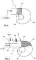
- the burner 17 is in the in FIG. 3 illustrated simplest embodiment constructed so that the burner 17 consists practically only of the combustion zone 23.
- This combustion zone 23 in turn consists of a material which is open-pored and has a high specific surface area.
- the material may be, for example, a knit of non-directional fibers, a collection of directional fibers, an open-pored foam, or an open-pored sintered material, for example, metallic or ceramic-based.
- the combustion zone 23 consists of a mesh or fabric of metallic or ceramic material and is designed as a so-called matrix burner or matrix radiation burner.
- the burner 17 is a catalytic burner.
- the material of the combustion zone 23 is thus provided with a catalytically active material which, for example, is finely distributed in the open-pored structure or at least covers parts of the surface of the open-pored structure in the form of a coating.
- a catalytic material for example, palladium, platinum or the like can be used. Due to the formation as a catalytic burner 17 are in the combustion zone 23 of the burner 17th the exhaust gases flowing to the burner 17 of the fuel cell 2, which are indicated here by an arrow as a gas mixture and from the discharge line 11, the exhaust duct 18, the hydrogen pipe 19 and the fresh air line 21 originate or fed, fed into the region of the combustion zone 23.
- catalytic combustion guarantees next to the provision of hot combustion gases at a temperature level of about 600 ° C to drive the turbine 24 an approximately complete implementation of the combustible materials in the gas stream flowing to the burner 17, so that emissions can be largely avoided.
- combustion zone 23 is formed integrally in the inlet area of a spiral turbine housing 29 of the turbine 24.
- This construction makes it possible to provide turbine 24 and burner 17 with minimal installation space.
- the distance over which the volume flow of hot exhaust gases from the burner 17 to the turbine 24 must be performed minimized.
- heat losses are avoided on the one hand and on the other hand can be largely dispensed expensive high-temperature resistant materials for the length of the wiring.
- Only the turbine housing must be formed from a corresponding high-temperature-resistant material or be coated at least in the region of its inner walls with such a material, for example on a ceramic basis.
- a possible problem with catalytic burners 17 may be that they may be difficult to ignite in certain operating situations or their so-called Reach light-off temperature until late, so that unburned substances can pass through the area of the combustion zone 23 therethrough.
- emissions and, on the other hand, substances which could be profitably converted into thermal energy can flow unused out of the fuel cell system 1.
- the structure of the burner 17 according to the invention in the turbine housing 29, as in the illustration of FIG. 4 can be seen, via an ignition device 30.
- the structure in the representation of FIG. 4 the burner 17 is also formed with a combustion zone 23 with a pore material.
- the exhaust gas from the fuel cell 2, ie in particular from the discharge line 11 and the exhaust air line 18, is fed via a line element 31.
- Hydrogen from the hydrogen line 19 and fresh air from the fresh air line 21 is supplied via a further line element 32.
- the ignition device 30 is arranged in the region of the line element 32, so that there is always a readily ignitable mixture of hydrogen and fresh air in its region.
- a monitoring electrode 33 can also be provided in the burner 17, by means of which an ignition can be verified.
- FIG. 4 illustrated burner 17 similar to that in the context of FIG. 3 built burner described.
- the combustion zone which also has an open-pore material in the manner of a pore burner, is wider than in the illustration of FIG. 3 integrated into the turbine housing 29, so that a very compact structure is formed, in which the hot exhaust gases from the region of the burner 17 only have to flow over a very small distance.
- the combustion zone 23 is again provided in particular with a catalytically active material, so that the burner 17 is formed as a catalytic burner.
- a comparable structure would also be conceivable for a burner 17 without a catalytic coating.
- a flame arrester 34 is also arranged.
- a flame arrester is known from the general state of the art and common in various types of burners. It typically consists of a perforated plate or the like, and retains flames from repelling from the area of the burner into the area of the incoming gases.
- the combustion zone 23 is designed as a combustion zone of a matrix burner or matrix radiation burner.
- the combustion zone 23 is formed as a typically curved element made of a fabric or mesh, typically on a metallic or ceramic basis.
- the combustion zone 23 may be part of a spherical cap, a cylinder or a cone.
- the material of the matrix which here forms the combustion zone 23 may also comprise a catalytic material, for example in which some or all of the fibers used to form the mesh have a catalytic coating.
- a third line element 35 via which cooling air from the range of in the context of FIG. 2 described cooling air line 27 can be supplied.
- this cooling air can lead to a reduction in the temperature of the combustion due to a corresponding excess air, so that, for example, permissible operating temperatures of the turbine 24 and / or the combustion zone 23 are not exceeded.
- the burner 17 builds ⁇ extremely compact and can either be performed directly integrated into the turbine housing 29 or connect directly to this turbine housing.
Landscapes
- Engineering & Computer Science (AREA)
- Chemical & Material Sciences (AREA)
- Combustion & Propulsion (AREA)
- Mechanical Engineering (AREA)
- General Engineering & Computer Science (AREA)
- Chemical Kinetics & Catalysis (AREA)
- Fuel Cell (AREA)
Claims (6)
- Système (1) de piles à combustible comprenant une turbine (24) et un dispositif destiné à mettre à disposition des gaz d'échappement chauds destinés à entraîner la turbine (24), qui présente un brûleur, dont la zone de combustion (23) est intégrée directement sur l'admission de gaz de la turbine (24) ou dans cette dernière, un gaz ou un mélange gazeux inflammable étant amené au brûleur (17), la zone de combustion (23) présentant un matériau à pores ouverts ayant une grande surface spécifique, et une pile à combustible (2), le brûleur (17) étant alimenté au moins en gaz d'échappement provenant de la pile à combustible (2), le brûleur (17) étant alimenté au moins partiellement en air frais, et le brûleur (17) présentant un dispositif d'allumage qui permet d'amorcer une combustion au moins de l'air frais et d'un combustible de la pile à combustible (2), caractérisé en ce que l'air frais et le combustible de la pile à combustible (2) sont réunis dans le sens de l'écoulement en aval du dispositif d'allumage (30) et en amont de la zone de combustion (23) conjointement avec les gaz d'échappement provenant de la pile à combustible (2).
- Système de pile à combustible (1) selon la revendication 1, caractérisé en ce que le matériau à pores ouverts présentant une grande surface spécifique présente au moins une matière catalytique active.
- Système de pile à combustible (1) selon la revendication 2, caractérisé en ce que la matière catalytique active comprend du palladium.
- Système de pile à combustible (1) selon la revendication 1, 2 ou 3, caractérisé en ce que l'air frais et le combustible provenant de la pile à combustible (2) sont guidés dans la zone du dispositif d'allumage (30) de sorte que localement se produise un mélange des deux matières pouvant être amorcées.
- Système de pile à combustible (1) selon l'une quelconque des revendications 1 à 4, caractérisé en ce que le dispositif d'allumage (30) allume le mélange de matière au moyen d'étincelles.
- Système de pile à combustible (1) selon l'une quelconque des revendications 1 à 5, caractérisé en ce que la turbine (24) dotée d'un compresseur (6) pour le flux d'air de traitement est couplée à la pile à combustible (2) et/ou à une machine électrique (17).
Applications Claiming Priority (2)
| Application Number | Priority Date | Filing Date | Title |
|---|---|---|---|
| DE102010010272A DE102010010272A1 (de) | 2010-03-05 | 2010-03-05 | Vorrichtung zur Bereitstellung von heißen Abgasen |
| PCT/EP2010/007379 WO2011107132A1 (fr) | 2010-03-05 | 2010-12-04 | Dispositif pour fournir des gaz d'échappement chauds |
Publications (2)
| Publication Number | Publication Date |
|---|---|
| EP2542836A1 EP2542836A1 (fr) | 2013-01-09 |
| EP2542836B1 true EP2542836B1 (fr) | 2016-09-07 |
Family
ID=43708748
Family Applications (1)
| Application Number | Title | Priority Date | Filing Date |
|---|---|---|---|
| EP10785366.5A Not-in-force EP2542836B1 (fr) | 2010-03-05 | 2010-12-04 | Dispositif pour fournir des gaz d'échappement chauds |
Country Status (6)
| Country | Link |
|---|---|
| US (1) | US20130029236A1 (fr) |
| EP (1) | EP2542836B1 (fr) |
| JP (1) | JP5771631B2 (fr) |
| CN (1) | CN102782412B (fr) |
| DE (1) | DE102010010272A1 (fr) |
| WO (1) | WO2011107132A1 (fr) |
Cited By (1)
| Publication number | Priority date | Publication date | Assignee | Title |
|---|---|---|---|---|
| WO2023165847A1 (fr) * | 2022-03-03 | 2023-09-07 | Robert Bosch Gmbh | Système de piles à combustible à récupération d'énergie |
Families Citing this family (4)
| Publication number | Priority date | Publication date | Assignee | Title |
|---|---|---|---|---|
| DE102012018877A1 (de) | 2012-09-25 | 2014-03-27 | Daimler Ag | Vorrichtung zur Energie(Rück-)gewinnung |
| DE112013005790B4 (de) * | 2012-12-05 | 2023-07-06 | Deutsches Zentrum für Luft- und Raumfahrt e.V. | Verfahren zum Betreiben eines Verbrennungssystems und Verbrennungssystem |
| CN109921063A (zh) * | 2017-12-13 | 2019-06-21 | 郑州宇通客车股份有限公司 | 一种燃料电池空气增湿系统、燃料电池系统及车辆 |
| AT521838B1 (de) * | 2018-10-22 | 2020-10-15 | Avl List Gmbh | Brennstoffzellensystem und Verfahren zum Betreiben desselben |
Citations (1)
| Publication number | Priority date | Publication date | Assignee | Title |
|---|---|---|---|---|
| DE10306234A1 (de) * | 2003-02-04 | 2004-08-12 | Daimlerchrysler Ag | Vorrichtung zur Luftversorgung einer Brennstoffzelle |
Family Cites Families (21)
| Publication number | Priority date | Publication date | Assignee | Title |
|---|---|---|---|---|
| JPS592767B2 (ja) * | 1971-11-10 | 1984-01-20 | エンゲルハ−ド ミネラルズ アンド ケミカルズ コ−ポレ−シヨン | タンソシツネンリヨウ ノ サンカニヨリガスタ−ビン オ ウンテンスルホウホウ |
| IT991349B (it) * | 1972-07-25 | 1975-07-30 | British Leyland Truck & Bus | Processo di combustione per combustibili idrocarburici specialmente applicabile a motori a turbina a gas |
| US3976507A (en) * | 1975-02-12 | 1976-08-24 | United Technologies Corporation | Pressurized fuel cell power plant with single reactant gas stream |
| JPS5975571A (ja) | 1982-10-23 | 1984-04-28 | Jgc Corp | 燃料電池発電システムにおける運転方法 |
| DE4032993C1 (fr) * | 1990-10-15 | 1992-05-07 | Mannesmann Ag, 4000 Duesseldorf, De | |
| JPH04324011A (ja) * | 1991-04-23 | 1992-11-13 | Osaka Gas Co Ltd | 触媒燃焼装置 |
| JPH06257465A (ja) * | 1993-03-10 | 1994-09-13 | Hitachi Ltd | ガスタービン発電装置 |
| JP3344439B2 (ja) * | 1994-01-11 | 2002-11-11 | 石川島播磨重工業株式会社 | タービンコンプレッサ用燃焼装置と燃焼方法 |
| JPH08206500A (ja) * | 1995-02-02 | 1996-08-13 | Toshiba Corp | パラジウム系触媒、燃焼触媒および燃焼器 |
| JP3030689B2 (ja) * | 1995-09-08 | 2000-04-10 | 本田技研工業株式会社 | ガスタービンエンジン |
| US5938975A (en) * | 1996-12-23 | 1999-08-17 | Ennis; Bernard | Method and apparatus for total energy fuel conversion systems |
| US6408611B1 (en) * | 2000-08-10 | 2002-06-25 | Honeywell International, Inc. | Fuel control method for gas turbine |
| JP2002089841A (ja) * | 2000-09-12 | 2002-03-27 | Ishikawajima Harima Heavy Ind Co Ltd | ガスタービン用燃焼器 |
| US20020157881A1 (en) | 2000-11-13 | 2002-10-31 | Daniel Bakholdin | Turbine power unit for hybrid electric vehicle applications |
| JP2002305009A (ja) * | 2001-04-04 | 2002-10-18 | Ishikawajima Harima Heavy Ind Co Ltd | 燃料電池複合発電装置 |
| DE10246231A1 (de) * | 2002-10-04 | 2004-04-15 | Robert Bosch Gmbh | Nachbrenneinrichtung |
| DE10250360A1 (de) * | 2002-10-29 | 2004-05-13 | Robert Bosch Gmbh | Nachbrenneinrichtung und Verfahren zum Betreiben einer Nachbrenneinrichtung |
| US7410713B2 (en) * | 2002-12-23 | 2008-08-12 | General Electric Company | Integrated fuel cell hybrid power plant with re-circulated air and fuel flow |
| US7666539B2 (en) * | 2003-06-27 | 2010-02-23 | Ultracell Corporation | Heat efficient portable fuel cell systems |
| JP2008251247A (ja) * | 2007-03-29 | 2008-10-16 | Mitsubishi Heavy Ind Ltd | 燃料電池ガスタービン複合発電システム及びその制御方法 |
| US20100095915A1 (en) * | 2008-10-16 | 2010-04-22 | Lincoln Evans-Beauchamp | External compression two-stroke internal combustion engine with burner manifold |
-
2010
- 2010-03-05 DE DE102010010272A patent/DE102010010272A1/de not_active Withdrawn
- 2010-12-04 EP EP10785366.5A patent/EP2542836B1/fr not_active Not-in-force
- 2010-12-04 WO PCT/EP2010/007379 patent/WO2011107132A1/fr not_active Ceased
- 2010-12-04 CN CN201080065194.3A patent/CN102782412B/zh not_active Expired - Fee Related
- 2010-12-04 US US13/582,690 patent/US20130029236A1/en not_active Abandoned
- 2010-12-04 JP JP2012555302A patent/JP5771631B2/ja not_active Expired - Fee Related
Patent Citations (1)
| Publication number | Priority date | Publication date | Assignee | Title |
|---|---|---|---|---|
| DE10306234A1 (de) * | 2003-02-04 | 2004-08-12 | Daimlerchrysler Ag | Vorrichtung zur Luftversorgung einer Brennstoffzelle |
Cited By (2)
| Publication number | Priority date | Publication date | Assignee | Title |
|---|---|---|---|---|
| WO2023165847A1 (fr) * | 2022-03-03 | 2023-09-07 | Robert Bosch Gmbh | Système de piles à combustible à récupération d'énergie |
| US12412911B2 (en) | 2022-03-03 | 2025-09-09 | Robert Bosch Gmbh | Fuel cell system having energy recuperation |
Also Published As
| Publication number | Publication date |
|---|---|
| JP5771631B2 (ja) | 2015-09-02 |
| CN102782412A (zh) | 2012-11-14 |
| US20130029236A1 (en) | 2013-01-31 |
| WO2011107132A1 (fr) | 2011-09-09 |
| DE102010010272A8 (de) | 2012-01-12 |
| JP2013521461A (ja) | 2013-06-10 |
| DE102010010272A1 (de) | 2011-09-08 |
| EP2542836A1 (fr) | 2013-01-09 |
| CN102782412B (zh) | 2015-05-27 |
Similar Documents
| Publication | Publication Date | Title |
|---|---|---|
| EP2580800B1 (fr) | Système à pile à combustible présentant une pile à combustible disposée dans un boîtier | |
| EP1465274B1 (fr) | Système de piles à combustible et un arrangement de brûleur pour un système de piles à combustible | |
| DE102008006953B4 (de) | System und Verfahren zur Reduktion von Schadstoffen in Triebwerksabgasen | |
| DE10306234B4 (de) | Verfahren zur Luftversorgung einer Brennstoffzelle und Vorrichtung zur Durchführung des Verfahrens | |
| DE112009003573T5 (de) | Brennstoffzellensystem mit Reoxidationsbarriere | |
| EP2399315A1 (fr) | Système de pile à combustible comportant au moins une pile à combustible | |
| EP2028350B1 (fr) | Système de moteur à combustion interne | |
| EP2542836A1 (fr) | Dispositif pour fournir des gaz d'échappement chauds | |
| DE102016203792A1 (de) | Brennstoffzellenmodul | |
| EP1947723B1 (fr) | Système d'approvisionnement d'énergie | |
| DE112007001313T5 (de) | Hybrid-Antriebssystem mit Brennstoffzelle und Motor | |
| DE102010047523A1 (de) | Brennstoffzellensystem mit wenigstens einer Brennstoffzelle | |
| EP1919018B1 (fr) | Système de pile à combustible | |
| DE10104607A1 (de) | Gaserzeugungssystem für ein Brennstoffzellensystem und Verfahren zum Betrieb eines Gaserzeugungssystems | |
| EP3899369B1 (fr) | Système de brûleur, système comprenant un tel système de brûleur et procédé de fourniture d'énergie thermique au moyen d'un tel système de brûleur | |
| DE102010010271A1 (de) | Vorrichtung zur Bereitstellung eines heißen Abgasstroms | |
| EP2028710B1 (fr) | Véhicule avec un moteur à combustion et un système de cellules combustibles | |
| DE10149014A1 (de) | Hochtemperatur-Brennstoffzellen-System und Verfahren zu seinem Betreiben | |
| DE102014115096B4 (de) | System zur versorgung eines fahrzeugs mit elektrischer energie | |
| DE102012018877A1 (de) | Vorrichtung zur Energie(Rück-)gewinnung | |
| EP1524240A1 (fr) | Dispositif d' évaporation pour la production d' hydrogène d' un mélange dégradable d' hydrocarbone/vapeur dans un réformeur | |
| DE102010034848B4 (de) | Zweistoff-Triebwerk | |
| EP1693916A1 (fr) | Préchauffeur pour pile à combustible | |
| DE10143156B4 (de) | Brennstoffzellensystem mit einer Vorrichtung zur Luftversorgung und Verfahren zum Betreiben des Brennstoffzellensystems und dessen Verwendung | |
| EP1739777A2 (fr) | Système de pile à combustible pour véhicules |
Legal Events
| Date | Code | Title | Description |
|---|---|---|---|
| PUAI | Public reference made under article 153(3) epc to a published international application that has entered the european phase |
Free format text: ORIGINAL CODE: 0009012 |
|
| 17P | Request for examination filed |
Effective date: 20120811 |
|
| AK | Designated contracting states |
Kind code of ref document: A1 Designated state(s): AL AT BE BG CH CY CZ DE DK EE ES FI FR GB GR HR HU IE IS IT LI LT LU LV MC MK MT NL NO PL PT RO RS SE SI SK SM TR |
|
| DAX | Request for extension of the european patent (deleted) | ||
| GRAP | Despatch of communication of intention to grant a patent |
Free format text: ORIGINAL CODE: EPIDOSNIGR1 |
|
| INTG | Intention to grant announced |
Effective date: 20160408 |
|
| GRAS | Grant fee paid |
Free format text: ORIGINAL CODE: EPIDOSNIGR3 |
|
| GRAA | (expected) grant |
Free format text: ORIGINAL CODE: 0009210 |
|
| AK | Designated contracting states |
Kind code of ref document: B1 Designated state(s): AL AT BE BG CH CY CZ DE DK EE ES FI FR GB GR HR HU IE IS IT LI LT LU LV MC MK MT NL NO PL PT RO RS SE SI SK SM TR |
|
| REG | Reference to a national code |
Ref country code: GB Ref legal event code: FG4D Free format text: NOT ENGLISH |
|
| REG | Reference to a national code |
Ref country code: CH Ref legal event code: EP |
|
| REG | Reference to a national code |
Ref country code: IE Ref legal event code: FG4D Free format text: LANGUAGE OF EP DOCUMENT: GERMAN |
|
| REG | Reference to a national code |
Ref country code: AT Ref legal event code: REF Ref document number: 827225 Country of ref document: AT Kind code of ref document: T Effective date: 20161015 |
|
| REG | Reference to a national code |
Ref country code: DE Ref legal event code: R096 Ref document number: 502010012374 Country of ref document: DE |
|
| REG | Reference to a national code |
Ref country code: LT Ref legal event code: MG4D |
|
| REG | Reference to a national code |
Ref country code: NL Ref legal event code: MP Effective date: 20160907 |
|
| PG25 | Lapsed in a contracting state [announced via postgrant information from national office to epo] |
Ref country code: NO Free format text: LAPSE BECAUSE OF FAILURE TO SUBMIT A TRANSLATION OF THE DESCRIPTION OR TO PAY THE FEE WITHIN THE PRESCRIBED TIME-LIMIT Effective date: 20161207 Ref country code: HR Free format text: LAPSE BECAUSE OF FAILURE TO SUBMIT A TRANSLATION OF THE DESCRIPTION OR TO PAY THE FEE WITHIN THE PRESCRIBED TIME-LIMIT Effective date: 20160907 Ref country code: FI Free format text: LAPSE BECAUSE OF FAILURE TO SUBMIT A TRANSLATION OF THE DESCRIPTION OR TO PAY THE FEE WITHIN THE PRESCRIBED TIME-LIMIT Effective date: 20160907 Ref country code: LT Free format text: LAPSE BECAUSE OF FAILURE TO SUBMIT A TRANSLATION OF THE DESCRIPTION OR TO PAY THE FEE WITHIN THE PRESCRIBED TIME-LIMIT Effective date: 20160907 Ref country code: RS Free format text: LAPSE BECAUSE OF FAILURE TO SUBMIT A TRANSLATION OF THE DESCRIPTION OR TO PAY THE FEE WITHIN THE PRESCRIBED TIME-LIMIT Effective date: 20160907 |
|
| PG25 | Lapsed in a contracting state [announced via postgrant information from national office to epo] |
Ref country code: LV Free format text: LAPSE BECAUSE OF FAILURE TO SUBMIT A TRANSLATION OF THE DESCRIPTION OR TO PAY THE FEE WITHIN THE PRESCRIBED TIME-LIMIT Effective date: 20160907 Ref country code: SE Free format text: LAPSE BECAUSE OF FAILURE TO SUBMIT A TRANSLATION OF THE DESCRIPTION OR TO PAY THE FEE WITHIN THE PRESCRIBED TIME-LIMIT Effective date: 20160907 Ref country code: NL Free format text: LAPSE BECAUSE OF FAILURE TO SUBMIT A TRANSLATION OF THE DESCRIPTION OR TO PAY THE FEE WITHIN THE PRESCRIBED TIME-LIMIT Effective date: 20160907 Ref country code: ES Free format text: LAPSE BECAUSE OF FAILURE TO SUBMIT A TRANSLATION OF THE DESCRIPTION OR TO PAY THE FEE WITHIN THE PRESCRIBED TIME-LIMIT Effective date: 20160907 Ref country code: GR Free format text: LAPSE BECAUSE OF FAILURE TO SUBMIT A TRANSLATION OF THE DESCRIPTION OR TO PAY THE FEE WITHIN THE PRESCRIBED TIME-LIMIT Effective date: 20161208 |
|
| PG25 | Lapsed in a contracting state [announced via postgrant information from national office to epo] |
Ref country code: RO Free format text: LAPSE BECAUSE OF FAILURE TO SUBMIT A TRANSLATION OF THE DESCRIPTION OR TO PAY THE FEE WITHIN THE PRESCRIBED TIME-LIMIT Effective date: 20160907 Ref country code: EE Free format text: LAPSE BECAUSE OF FAILURE TO SUBMIT A TRANSLATION OF THE DESCRIPTION OR TO PAY THE FEE WITHIN THE PRESCRIBED TIME-LIMIT Effective date: 20160907 |
|
| PG25 | Lapsed in a contracting state [announced via postgrant information from national office to epo] |
Ref country code: SK Free format text: LAPSE BECAUSE OF FAILURE TO SUBMIT A TRANSLATION OF THE DESCRIPTION OR TO PAY THE FEE WITHIN THE PRESCRIBED TIME-LIMIT Effective date: 20160907 Ref country code: PT Free format text: LAPSE BECAUSE OF FAILURE TO SUBMIT A TRANSLATION OF THE DESCRIPTION OR TO PAY THE FEE WITHIN THE PRESCRIBED TIME-LIMIT Effective date: 20170109 Ref country code: SM Free format text: LAPSE BECAUSE OF FAILURE TO SUBMIT A TRANSLATION OF THE DESCRIPTION OR TO PAY THE FEE WITHIN THE PRESCRIBED TIME-LIMIT Effective date: 20160907 Ref country code: BE Free format text: LAPSE BECAUSE OF NON-PAYMENT OF DUE FEES Effective date: 20161231 Ref country code: BG Free format text: LAPSE BECAUSE OF FAILURE TO SUBMIT A TRANSLATION OF THE DESCRIPTION OR TO PAY THE FEE WITHIN THE PRESCRIBED TIME-LIMIT Effective date: 20161207 Ref country code: PL Free format text: LAPSE BECAUSE OF FAILURE TO SUBMIT A TRANSLATION OF THE DESCRIPTION OR TO PAY THE FEE WITHIN THE PRESCRIBED TIME-LIMIT Effective date: 20160907 Ref country code: IS Free format text: LAPSE BECAUSE OF FAILURE TO SUBMIT A TRANSLATION OF THE DESCRIPTION OR TO PAY THE FEE WITHIN THE PRESCRIBED TIME-LIMIT Effective date: 20170107 Ref country code: CZ Free format text: LAPSE BECAUSE OF FAILURE TO SUBMIT A TRANSLATION OF THE DESCRIPTION OR TO PAY THE FEE WITHIN THE PRESCRIBED TIME-LIMIT Effective date: 20160907 |
|
| REG | Reference to a national code |
Ref country code: DE Ref legal event code: R097 Ref document number: 502010012374 Country of ref document: DE |
|
| PG25 | Lapsed in a contracting state [announced via postgrant information from national office to epo] |
Ref country code: IT Free format text: LAPSE BECAUSE OF FAILURE TO SUBMIT A TRANSLATION OF THE DESCRIPTION OR TO PAY THE FEE WITHIN THE PRESCRIBED TIME-LIMIT Effective date: 20160907 |
|
| REG | Reference to a national code |
Ref country code: DE Ref legal event code: R119 Ref document number: 502010012374 Country of ref document: DE |
|
| PLBE | No opposition filed within time limit |
Free format text: ORIGINAL CODE: 0009261 |
|
| STAA | Information on the status of an ep patent application or granted ep patent |
Free format text: STATUS: NO OPPOSITION FILED WITHIN TIME LIMIT |
|
| PG25 | Lapsed in a contracting state [announced via postgrant information from national office to epo] |
Ref country code: DK Free format text: LAPSE BECAUSE OF FAILURE TO SUBMIT A TRANSLATION OF THE DESCRIPTION OR TO PAY THE FEE WITHIN THE PRESCRIBED TIME-LIMIT Effective date: 20160907 |
|
| REG | Reference to a national code |
Ref country code: CH Ref legal event code: PL |
|
| 26N | No opposition filed |
Effective date: 20170608 |
|
| GBPC | Gb: european patent ceased through non-payment of renewal fee |
Effective date: 20161207 |
|
| PG25 | Lapsed in a contracting state [announced via postgrant information from national office to epo] |
Ref country code: SI Free format text: LAPSE BECAUSE OF FAILURE TO SUBMIT A TRANSLATION OF THE DESCRIPTION OR TO PAY THE FEE WITHIN THE PRESCRIBED TIME-LIMIT Effective date: 20160907 |
|
| PG25 | Lapsed in a contracting state [announced via postgrant information from national office to epo] |
Ref country code: MC Free format text: LAPSE BECAUSE OF FAILURE TO SUBMIT A TRANSLATION OF THE DESCRIPTION OR TO PAY THE FEE WITHIN THE PRESCRIBED TIME-LIMIT Effective date: 20160907 |
|
| REG | Reference to a national code |
Ref country code: FR Ref legal event code: ST Effective date: 20170831 |
|
| REG | Reference to a national code |
Ref country code: IE Ref legal event code: MM4A |
|
| PG25 | Lapsed in a contracting state [announced via postgrant information from national office to epo] |
Ref country code: LI Free format text: LAPSE BECAUSE OF NON-PAYMENT OF DUE FEES Effective date: 20161231 Ref country code: CH Free format text: LAPSE BECAUSE OF NON-PAYMENT OF DUE FEES Effective date: 20161231 Ref country code: FR Free format text: LAPSE BECAUSE OF NON-PAYMENT OF DUE FEES Effective date: 20170102 Ref country code: LU Free format text: LAPSE BECAUSE OF NON-PAYMENT OF DUE FEES Effective date: 20161204 |
|
| PG25 | Lapsed in a contracting state [announced via postgrant information from national office to epo] |
Ref country code: IE Free format text: LAPSE BECAUSE OF NON-PAYMENT OF DUE FEES Effective date: 20161204 Ref country code: DE Free format text: LAPSE BECAUSE OF NON-PAYMENT OF DUE FEES Effective date: 20170701 Ref country code: GB Free format text: LAPSE BECAUSE OF NON-PAYMENT OF DUE FEES Effective date: 20161207 |
|
| REG | Reference to a national code |
Ref country code: BE Ref legal event code: MM Effective date: 20161231 |
|
| REG | Reference to a national code |
Ref country code: AT Ref legal event code: MM01 Ref document number: 827225 Country of ref document: AT Kind code of ref document: T Effective date: 20161204 |
|
| PG25 | Lapsed in a contracting state [announced via postgrant information from national office to epo] |
Ref country code: HU Free format text: LAPSE BECAUSE OF FAILURE TO SUBMIT A TRANSLATION OF THE DESCRIPTION OR TO PAY THE FEE WITHIN THE PRESCRIBED TIME-LIMIT; INVALID AB INITIO Effective date: 20101204 Ref country code: CY Free format text: LAPSE BECAUSE OF FAILURE TO SUBMIT A TRANSLATION OF THE DESCRIPTION OR TO PAY THE FEE WITHIN THE PRESCRIBED TIME-LIMIT Effective date: 20160907 Ref country code: AT Free format text: LAPSE BECAUSE OF NON-PAYMENT OF DUE FEES Effective date: 20161204 |
|
| PG25 | Lapsed in a contracting state [announced via postgrant information from national office to epo] |
Ref country code: MK Free format text: LAPSE BECAUSE OF FAILURE TO SUBMIT A TRANSLATION OF THE DESCRIPTION OR TO PAY THE FEE WITHIN THE PRESCRIBED TIME-LIMIT Effective date: 20160907 Ref country code: TR Free format text: LAPSE BECAUSE OF FAILURE TO SUBMIT A TRANSLATION OF THE DESCRIPTION OR TO PAY THE FEE WITHIN THE PRESCRIBED TIME-LIMIT Effective date: 20160907 |
|
| PG25 | Lapsed in a contracting state [announced via postgrant information from national office to epo] |
Ref country code: MT Free format text: LAPSE BECAUSE OF FAILURE TO SUBMIT A TRANSLATION OF THE DESCRIPTION OR TO PAY THE FEE WITHIN THE PRESCRIBED TIME-LIMIT Effective date: 20160907 |
|
| PG25 | Lapsed in a contracting state [announced via postgrant information from national office to epo] |
Ref country code: AL Free format text: LAPSE BECAUSE OF FAILURE TO SUBMIT A TRANSLATION OF THE DESCRIPTION OR TO PAY THE FEE WITHIN THE PRESCRIBED TIME-LIMIT Effective date: 20160907 |
|
| RIC2 | Information provided on ipc code assigned after grant |
Ipc: F23C 13/00 20060101ALI20110919BHEP Ipc: B60K 6/26 20071001ALI20110919BHEP Ipc: F23C 13/08 20060101ALI20110919BHEP Ipc: F23R 3/40 20060101AFI20110919BHEP |