EP2543316B1 - Appareil permettant de mesurer la luminance et la température d'une source de lumière d'un dispositif spectrophotométrique - Google Patents
Appareil permettant de mesurer la luminance et la température d'une source de lumière d'un dispositif spectrophotométrique Download PDFInfo
- Publication number
- EP2543316B1 EP2543316B1 EP12175451.9A EP12175451A EP2543316B1 EP 2543316 B1 EP2543316 B1 EP 2543316B1 EP 12175451 A EP12175451 A EP 12175451A EP 2543316 B1 EP2543316 B1 EP 2543316B1
- Authority
- EP
- European Patent Office
- Prior art keywords
- measuring device
- photodiode
- luminance
- operable
- temperature
- Prior art date
- Legal status (The legal status is an assumption and is not a legal conclusion. Google has not performed a legal analysis and makes no representation as to the accuracy of the status listed.)
- Active
Links
Images


Classifications
-
- A—HUMAN NECESSITIES
- A61—MEDICAL OR VETERINARY SCIENCE; HYGIENE
- A61B—DIAGNOSIS; SURGERY; IDENTIFICATION
- A61B5/00—Measuring for diagnostic purposes; Identification of persons
- A61B5/145—Measuring characteristics of blood in vivo, e.g. gas concentration or pH-value ; Measuring characteristics of body fluids or tissues, e.g. interstitial fluid or cerebral tissue
- A61B5/1455—Measuring characteristics of blood in vivo, e.g. gas concentration or pH-value ; Measuring characteristics of body fluids or tissues, e.g. interstitial fluid or cerebral tissue using optical sensors, e.g. spectral photometrical oximeters
-
- A—HUMAN NECESSITIES
- A61—MEDICAL OR VETERINARY SCIENCE; HYGIENE
- A61B—DIAGNOSIS; SURGERY; IDENTIFICATION
- A61B2560/00—Constructional details of operational features of apparatus; Accessories for medical measuring apparatus
- A61B2560/02—Operational features
- A61B2560/0242—Operational features adapted to measure environmental factors, e.g. temperature, pollution
- A61B2560/0247—Operational features adapted to measure environmental factors, e.g. temperature, pollution for compensation or correction of the measured physiological value
- A61B2560/0252—Operational features adapted to measure environmental factors, e.g. temperature, pollution for compensation or correction of the measured physiological value using ambient temperature
-
- A—HUMAN NECESSITIES
- A61—MEDICAL OR VETERINARY SCIENCE; HYGIENE
- A61B—DIAGNOSIS; SURGERY; IDENTIFICATION
- A61B2562/00—Details of sensors; Constructional details of sensor housings or probes; Accessories for sensors
- A61B2562/02—Details of sensors specially adapted for in-vivo measurements
- A61B2562/0233—Special features of optical sensors or probes classified in A61B5/00
- A61B2562/0238—Optical sensor arrangements for performing transmission measurements on body tissue
-
- A—HUMAN NECESSITIES
- A61—MEDICAL OR VETERINARY SCIENCE; HYGIENE
- A61B—DIAGNOSIS; SURGERY; IDENTIFICATION
- A61B2562/00—Details of sensors; Constructional details of sensor housings or probes; Accessories for sensors
- A61B2562/02—Details of sensors specially adapted for in-vivo measurements
- A61B2562/0271—Thermal or temperature sensors
Definitions
- Spectrophotometric devices are used to non-invasively measure biological tissue oxygenation by subjecting tissue to various wavelengths of light and observing tissue absorption characteristics.
- Light-emitting diodes LEDs are frequently used as the light source in these spectrophotometric devices because they are small, inexpensive, and available at a variety of wavelengths. LEDs can be problematic, however, because their output characteristics, such as luminous intensity and center wavelength, can change based on factors like drive current, temperature, and aging. In particular, temperature can be highly variable, especially when the spectrophotometric device is used in conjunction with techniques such as therapeutic hypothermia.
- the above-mentioned factors i.e., drive current, temperature, etc.
- the spectrophotometric device controls drive current to the LEDs to maintain a consistent light output from the part. This control mechanism only provides an indirect indicator of the actual light produced by the LEDs and does not monitor changes due to temperature variations.
- a system for measuring the luminance and temperature of a light source element of a spectrophotometric device is provided according to claim 1.
- a NIRS sensor includes an LED light source such a photodiode.
- the photodiode is disposed within sufficient proximity of the light source so as to enable measurement of the luminance and temperature of the light source.
- the photodiode is adapted to send signals to one or both of a luminance measuring device operable to measure luminance of the light signals received by the photodiode, and a temperature measuring device operable to measure the temperature of the photodiode.
- FIG. 1 a block diagram of a system 10 for measuring the luminous intensity (i.e., luminance) and temperature of a light source of a spectrophotometric device is illustrated.
- the system 10 includes a photodiode 20, a luminance measuring device 40, a temperature measuring device 60, a controller 80, a first switch 100 and a second switch 120.
- the photodiode 20 is operable to receive light signals 22 emitted by a light source of a spectrophotometric device and passing through a subject's body tissue.
- the luminance measuring device 40 is operable to measure luminance of the light signals 22 received by the
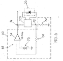
- FIG. 6 is a circuit diagram showing a temperature measuring device.
- FIG. 1 a block diagram of a system 10 for measuring the luminous intensity (i.e., luminance) and temperature of a light source of a spectrophotometric device is illustrated.
- the system 10 includes a photodiode 20, a luminance measuring device 40, a temperature measuring device 60, a controller 80, a first switch 100 and a second switch 120.
- the photodiode 20 is operable to receive light signals 22 emitted by a light source of a spectrophotometric device and passing through a subject's body tissue.
- the luminance measuring device 40 is operable to measure luminance of the light signals 22 received by the photodiode 20.
- the temperature measuring device 60 is operable to measure the temperature of the photodiode 20.
- the first switch 100 is operable to connect the photodiode 20 to the luminance measuring device 40 or the temperature measuring device 60.
- the second switch 120 is operable to connect the spectrophotometric device to the luminance measuring device 40 or the temperature measuring device 60.
- the controller 80 is operable to control the connection of the first and second switches 100, 120.
- an acceptable spectrophotometric device includes the near-infrared spectroscopy (NIRS) device disclosed in U.S. Patent Application No. 12/090,671 (hereinafter "the '671 application"), published under No. 2009/0182209 A1 .
- the NIRS device includes a NIRS sensor 140 and a processor.
- the NIRS sensor 140 illustrated in FIG. 2 , includes a light source 142, a near light detector 144 and a far light detector 146.
- the NIRS sensor 140 is adapted for use with the processor, which provides signals to and/or receives signals from the NIRS sensor 140.
- the light source 142 is selectively operable tu emit infrared light.
- the light source 142 may comprise, for example, a LED or a laser diode.
- a light guide e.g., fiber optics
- the near light detector 144 and the far light detector 146 each include a light responsive transducer such as a photodiode that is operative to sense luminous intensity derived from light emitted by the light source 142 after such light passes through the subject's body.
- the light detectors 144, 146 are electrically connected to the processor of the NIRS device. The relative spacing between the light source 142, near light detector 144 and far light detector 146 is of considerable importance relative to the sensing desired.
- the relative spacing includes: (1) a separation distance ("D2") between the light source 142 and the near light detector 144 that is great enough such that the near light detector 144 is positioned outside of any optical shunt field 148 (the shunt field 148 extends a distance "D1" out from the light source 142); and (2) the separation distance ("D3") between the far light detector 146 and the near light detector 144 is greater than the separation distance between the light source 142 and the near light detector 144 (i.e., D3 > D2 > D1).
- the present system 10 is not limited to use with the NIRS device described in the '671 application.
- the NIRS sensor 140 may include one or more of the luminance measuring device 40, temperature measuring device 60, first switch 100, second switch 120, and controller 80.
- the photodiode 20 of the present system may comprise any commercially available photodiode.
- the near light detector 144 or the far light detector 146 of the NIRS sensor 140 may function as the photodiode 20 of the present system 10.
- the photodiode 20 of the present system 10 may be a separate element from the near light detector 144 and the far light detector 146 of the NIRS sensor 10.
- the photodiode 20 of the present system 10 will be described hereinafter as being a separate element from the near light detector 144 and the far light detector 146 of the NIRS sensor 140.
- the photodiode 20 is disposed within the package of the NIRS sensor 140.
- the photodiode 20 is disposed within sufficient proximity of the light source 142 of the NIRS sensor 140 so as to enable measurement of the luminance and temperature of the light source 142.
- An example of an acceptable photodiode is a silicon-based photodiode.
- the present system 10 is limited to use with any particular photodiode, however.
- the luminance measuring device 40 comprises circuitry 42, 44 for converting a signal received from the photodiode 20 into a signal indicative of the luminance of the light signals received by the photodiode 20.
- the luminance measuring device 40 comprises a photovoltaic circuit 42.
- FIG. 4 illustrates the configuration that results after the controller 80 controls the first switch 100 to connect the photodiode 20 to the luminance measuring device 40, as is described further below.
- the input 46 of the photovoltaic circuit 42 receives signals from the photodiode 20.
- the photovoltaic circuit 42 is zero biased and has a zero ohm input impedance.
- the output 48 of the photovoltaic circuit 42 is connected to the second switch 120 (see FIG. 1 ).
- the photovoltaic circuit 42 is well-suited for applications in which accuracy of the luminance measurements is emphasized relative to the speed of the measurements.
- the luminance measuring device 40 may comprise a photoconductive circuit 44.
- FIG. 5 illustrates the configuration that results after the controller 80 connects the photodiode 20 to the luminance measuring device 40, as is described further below.
- the input 50 of the photoconductive circuit 44 receives a signal from the photodiode 20.
- the photoconductive circuit 44 has a reverse voltage bias 52 applied.
- the output 54 of the photoconductive circuit 44 is connected to the second switch 120 (see FIG. 1 ).
- the photoconductive circuit 44 is well-suited for applications in which the speed of the luminance measurements is emphasized relative to the accuracy of the measurements.
- the luminance measuring device 40 is not limited to any particular photoconductive circuit embodiment.
- the temperature measuring device 60 comprises a circuit 62 for converting a signal received from the photodiode 20 into a signal indicative of the temperature of the photodiode 20.
- the temperature measuring device 60 comprises a circuit 62 that biases the photodiode 20 with a constant current.
- the circuit 62 comprises an op-amp 64, a first load 66, a second load 68 and a voltage source 70.
- the input 72 of the circuit 62 receives a signal from the photodiode 20.
- the output 74 of the circuit 62 is connected to the second switch 120 (see FIG. 1 ).
- the temperature measuring device 60 may further comprise a unity gain differential amplifier (not shown) operable to adjust the output 74 to account for the nominal voltage of the photodiode 20.
- the temperature measuring device 60 may further comprise an amplifier (not shown) for adding gain to the output 74. The magnitude of the gain may vary depending on the resolution required by the spectrophotometric device. While the temperature measuring device 60 is described in terms of its preferred embodiment, it is not limited to any particular embodiment.
- the first switch 100 is disposed between the photodiode 20, the luminance measuring device 40 and the temperature measuring device 60.
- the first switch 100 is operable to connect the photodiode 20 to one of the luminance measuring device 40 or the temperature measuring device 60.
- the first switch 100 is operable to receive electronic signals from, and is operable to be controlled by, the controller 80.
- the first switch 100 comprises a semiconductor CMOS analog switch.
- the first switch 100 is not limited to this embodiment, however.
- the second switch 120 is disposed between the luminance measuring device 40 and the temperature measuring device 60 and the spectrophotometric device.
- the second switch 120 is operable to connect one of the luminance measuring device 40 or the temperature measuring device 60 to the spectrophotometric device (i.e., the processor of the NIRS device).
- the second switch 120 is operable to receive electronic signals from, and is operable to be controlled by, the controller 80.
- the second switch 120 comprises a semiconductor CMOS analog switch.
- the second switch 120 is not limited to this embodiment, however.
- the controller 80 is operable to control the connections of the first switch 100 and the second switch 120. That is, with regard to the first switch 100, the controller 80 is operable to control whether the first switch 100 connects the photodiode 20 to the luminance measuring device 40 or to the temperature measuring device 60. Similarly, with regard to the second switch 120, the controller 80 is operable to control whether the second switch 120 connects the luminance measuring device 40 or the temperature measuring device 60 to the spectrophotometric device.
- the controller 80 is preferably adapted for providing signals to and/or receiving signals from the spectrophotometric device (i.e., the processor of the NIRS device).
- the present system 10 selectively alternates between luminous intensity measurement and temperature measurements of the photodiode 20.
- the configuration (i.e., connection) of the first and second switches 100, 120 determines whether luminous intensity or temperature is being measured.
- the controller 80 simultaneously controls the configuration of the first and second switches 100, 120 such that when the first switch 100 connects the photodiode 20 to the luminance measuring device 40, the second switch 120 connects the luminance measuring device 40 to the spectrophotometric device (i.e., the processor of the NIRS device), and such that when the first switch 100 connects the photodiode 20 to the temperature measuring device 60, the second switch 120 connects the temperature measuring device 60 to the spectrophotometric device (i.e., the processor of the NIRS device).
- the outputs 48, 54, 74 of the luminance measuring device 40 and temperature measuring device 60 provide signals to the processor of the NIRS device, and the processor is operable to adjust the intensity of the light source 142 in response thereto.
- the processor may make adjustments based on information relating to light sensitivity characteristics or temperature characteristics that were recorded at time of manufacture into a memory device permanently associated with the processor.
Landscapes
- Health & Medical Sciences (AREA)
- Physics & Mathematics (AREA)
- Life Sciences & Earth Sciences (AREA)
- Biomedical Technology (AREA)
- Medical Informatics (AREA)
- Biophysics (AREA)
- Pathology (AREA)
- Engineering & Computer Science (AREA)
- Spectroscopy & Molecular Physics (AREA)
- Heart & Thoracic Surgery (AREA)
- Optics & Photonics (AREA)
- Molecular Biology (AREA)
- Surgery (AREA)
- Animal Behavior & Ethology (AREA)
- General Health & Medical Sciences (AREA)
- Public Health (AREA)
- Veterinary Medicine (AREA)
- Photometry And Measurement Of Optical Pulse Characteristics (AREA)
- Radiation Pyrometers (AREA)
Claims (10)
- Système de mesure de la luminance et de la température d'un élément de source de lumière d'un dispositif spectrophotométrique, le système comprenant : une photodiode (20) qui est à même de recevoir des signaux lumineux émis par l'élément de source de lumière et passant à travers le tissu corporel d'un sujet ; caractérisé par :un dispositif de mesure de luminance (40) qui est à même de mesurer une luminance des signaux lumineux reçus par la photodiode (20) ;un dispositif de mesure de température (60) qui est à même de mesurer la température de la photodiode (20), le dispositif de mesure de température (60) comprenant un circuit (62) pour convertir un signal reçu de la photodiode (20) en un signal indicatif de la température de la photodiode (20) ;un premier commutateur (100) qui est à même de connecter la photodiode (20) au dispositif de mesure de luminance (40) ou au dispositif de mesure de température (60) ; etun dispositif de commande (80) qui est à même de commander la connexion du premier commutateur (100).
- Système selon la revendication 1, comprenant en outre :un second commutateur (120) qui est à même de connecter le dispositif spectrophotométrique au dispositif de mesure de luminance (40) ou au dispositif de mesure de température (60) ;dans lequel le dispositif de commande (80) est en outre à même de commander la connexion du second commutateur (120).
- Système selon la revendication 2, dans lequel le dispositif de commande (80) est à même de commander simultanément le premier et le second commutateur (100, 120).
- Système selon l'une quelconque des revendications 1, 2 ou 3, dans lequel le dispositif de mesure de luminance (40) comprend un circuit photovoltaïque (42).
- Système selon l'une quelconque des revendications 1, 2 ou 3, dans lequel le dispositif de mesure de luminance (40) comprend un circuit photoconducteur (44).
- Système selon l'une quelconque des revendications précédentes, dans lequel le circuit (62) est à même de simuler une source de courant constant.
- Capteur NIRS, comprenant :une source de lumière DEL (142) ; etle système selon l'une quelconque des revendications précédentes, dans lequel la photodiode (20) est disposée à proximité suffisante de la source de lumière pour permettre une mesure de la luminance et de la température de la source de lumière.
- Capteur NIRS selon la revendication 7, comprenant en outre au moins un premier détecteur de lumière (144) disposé à une première distance de la source de lumière (142).
- Capteur NIRS selon la revendication 8, comprenant en outre au moins un second détecteur de lumière (146) disposé à une seconde distance de la source de lumière (142), laquelle seconde distance est supérieure à la première distance.
- Dispositif NIRS comprenant :le capteur NIRS (140) selon l'une quelconque des revendications 7 à 9 ; etun processeur, dans lequel les sorties du dispositif de mesure de luminance (40) et du dispositif de mesure de température (60) fournissent des signaux au processeur et le processeur est à même de régler l'intensité de la source de lumière (142) en réponse à ces signaux.
Applications Claiming Priority (1)
| Application Number | Priority Date | Filing Date | Title |
|---|---|---|---|
| US201161504927P | 2011-07-06 | 2011-07-06 |
Publications (2)
| Publication Number | Publication Date |
|---|---|
| EP2543316A1 EP2543316A1 (fr) | 2013-01-09 |
| EP2543316B1 true EP2543316B1 (fr) | 2018-09-26 |
Family
ID=46551379
Family Applications (1)
| Application Number | Title | Priority Date | Filing Date |
|---|---|---|---|
| EP12175451.9A Active EP2543316B1 (fr) | 2011-07-06 | 2012-07-06 | Appareil permettant de mesurer la luminance et la température d'une source de lumière d'un dispositif spectrophotométrique |
Country Status (2)
| Country | Link |
|---|---|
| US (1) | US9782109B2 (fr) |
| EP (1) | EP2543316B1 (fr) |
Families Citing this family (7)
| Publication number | Priority date | Publication date | Assignee | Title |
|---|---|---|---|---|
| US9888873B2 (en) * | 2012-12-10 | 2018-02-13 | Cas Medical Systems, Inc. | NIRS sensor assembly including EMI shielding |
| EP2928371B1 (fr) | 2012-12-10 | 2021-06-02 | Edwards Lifesciences Corporation | Procédé de détermination d'un paramètre lié à l'oxygène dans le sang par spectrophotométrie |
| US10467839B2 (en) * | 2014-10-21 | 2019-11-05 | CoinedBox, Inc. | Systems and methods for coin counting |
| EP3023056B1 (fr) | 2014-11-20 | 2021-03-24 | Edwards Lifesciences Corporation | Capteur spectrophotométrique |
| EP3271882B1 (fr) * | 2015-03-20 | 2019-05-08 | Wenda S.r.L. | Dispositif et procédé pour surveiller un produit alimentaire liquide |
| US10952603B2 (en) | 2016-07-13 | 2021-03-23 | Carl Zeiss Meditec, Inc. | Systems and methods for improved anterior segment OCT imaging |
| US12055921B2 (en) * | 2020-03-04 | 2024-08-06 | International Business Machines Corporation | Quality control based on measurements from verified sensors |
Family Cites Families (6)
| Publication number | Priority date | Publication date | Assignee | Title |
|---|---|---|---|---|
| US5477853A (en) | 1992-12-01 | 1995-12-26 | Somanetics Corporation | Temperature compensation method and apparatus for spectroscopic devices |
| US5715173A (en) | 1994-06-27 | 1998-02-03 | Dainippon Screen Mfg. Co., Ltd. | Concentration controlling method and a substate treating apparatus utilizing same |
| US6723054B1 (en) * | 1998-08-24 | 2004-04-20 | Empirical Technologies Corporation | Apparatus and method for measuring pulse transit time |
| US8965472B2 (en) | 2005-10-21 | 2015-02-24 | Cas Medical Systems, Inc. | Method and apparatus for spectrophotometric based oximetry |
| US8401604B2 (en) * | 2008-04-11 | 2013-03-19 | Glucovista, Llc | Apparatus and methods for non-invasive measurement of a substance within a body |
| WO2009142853A1 (fr) * | 2008-05-22 | 2009-11-26 | The Curators Of The University Of Missouri | Procédé et système de détection optique non invasif du glucose sanguin utilisant l’analyse de données spectrales |
-
2012
- 2012-07-06 EP EP12175451.9A patent/EP2543316B1/fr active Active
- 2012-07-06 US US13/543,180 patent/US9782109B2/en active Active
Non-Patent Citations (1)
| Title |
|---|
| None * |
Also Published As
| Publication number | Publication date |
|---|---|
| US20130012822A1 (en) | 2013-01-10 |
| EP2543316A1 (fr) | 2013-01-09 |
| US9782109B2 (en) | 2017-10-10 |
Similar Documents
| Publication | Publication Date | Title |
|---|---|---|
| EP2543316B1 (fr) | Appareil permettant de mesurer la luminance et la température d'une source de lumière d'un dispositif spectrophotométrique | |
| EP0290272B1 (fr) | Appareil d'examen pour mesurer l'état d'oxygénation | |
| US6444970B1 (en) | Miniature low-noise photodiode system | |
| US7744275B2 (en) | Optical fiber temperature sensing device | |
| US9322756B2 (en) | Nondispersive infrared micro-optics sensor for blood alcohol concentration measurements | |
| US4376890A (en) | Fiber-optic temperature-measuring apparatus | |
| US5477853A (en) | Temperature compensation method and apparatus for spectroscopic devices | |
| JP5522913B2 (ja) | 植物用センサ装置 | |
| JP2020534529A5 (fr) | ||
| US8649012B2 (en) | Optical gas sensor | |
| EP2400284A2 (fr) | Dispositif de mesure de la distribution de la température de fibre optique | |
| JPH04256733A (ja) | 血液パラメーターの測定装置およびその方法 | |
| FI3758606T3 (fi) | Menetelmä valonlähteen intensiteetin valitsemiseksi veressä olevan analyytin seuraamiseksi ja laite sitä varten | |
| CN103385711B (zh) | 基于mems的人体生理参数检测装置 | |
| JP6220065B2 (ja) | 生体光計測装置、及び方法 | |
| CN111198289A (zh) | 一种光纤式电流测量装置的控制方法 | |
| JPWO2020129989A1 (ja) | ビリルビン濃度測定システム | |
| US20100320386A1 (en) | Adhesive Sensor for Hot Melt and Liquid Adhesives | |
| US11684273B2 (en) | Tunable optoelectronic device and blood pressure sensor including the same | |
| EP3267882B1 (fr) | Sonde à axe optique incliné | |
| JP4910867B2 (ja) | 光ファイバ式温度センサ装置 | |
| KR20150113575A (ko) | Mcu 타입 먼지센서 | |
| US12471792B2 (en) | Tapped light in a laser-based photoplethysmographic device | |
| EP4685445A1 (fr) | Électronique de lecture de spectromètre intégré | |
| EP0216458A1 (fr) | Pyromètre détecteur de la température |
Legal Events
| Date | Code | Title | Description |
|---|---|---|---|
| PUAI | Public reference made under article 153(3) epc to a published international application that has entered the european phase |
Free format text: ORIGINAL CODE: 0009012 |
|
| AK | Designated contracting states |
Kind code of ref document: A1 Designated state(s): AL AT BE BG CH CY CZ DE DK EE ES FI FR GB GR HR HU IE IS IT LI LT LU LV MC MK MT NL NO PL PT RO RS SE SI SK SM TR |
|
| AX | Request for extension of the european patent |
Extension state: BA ME |
|
| 17P | Request for examination filed |
Effective date: 20130709 |
|
| RBV | Designated contracting states (corrected) |
Designated state(s): AL AT BE BG CH CY CZ DE DK EE ES FI FR GB GR HR HU IE IS IT LI LT LU LV MC MK MT NL NO PL PT RO RS SE SI SK SM TR |
|
| 17Q | First examination report despatched |
Effective date: 20160818 |
|
| STAA | Information on the status of an ep patent application or granted ep patent |
Free format text: STATUS: EXAMINATION IS IN PROGRESS |
|
| GRAP | Despatch of communication of intention to grant a patent |
Free format text: ORIGINAL CODE: EPIDOSNIGR1 |
|
| STAA | Information on the status of an ep patent application or granted ep patent |
Free format text: STATUS: GRANT OF PATENT IS INTENDED |
|
| INTG | Intention to grant announced |
Effective date: 20180406 |
|
| GRAS | Grant fee paid |
Free format text: ORIGINAL CODE: EPIDOSNIGR3 |
|
| GRAA | (expected) grant |
Free format text: ORIGINAL CODE: 0009210 |
|
| STAA | Information on the status of an ep patent application or granted ep patent |
Free format text: STATUS: THE PATENT HAS BEEN GRANTED |
|
| AK | Designated contracting states |
Kind code of ref document: B1 Designated state(s): AL AT BE BG CH CY CZ DE DK EE ES FI FR GB GR HR HU IE IS IT LI LT LU LV MC MK MT NL NO PL PT RO RS SE SI SK SM TR |
|
| REG | Reference to a national code |
Ref country code: GB Ref legal event code: FG4D |
|
| REG | Reference to a national code |
Ref country code: CH Ref legal event code: EP |
|
| REG | Reference to a national code |
Ref country code: AT Ref legal event code: REF Ref document number: 1045059 Country of ref document: AT Kind code of ref document: T Effective date: 20181015 |
|
| REG | Reference to a national code |
Ref country code: IE Ref legal event code: FG4D |
|
| REG | Reference to a national code |
Ref country code: DE Ref legal event code: R096 Ref document number: 602012051461 Country of ref document: DE |
|
| REG | Reference to a national code |
Ref country code: NL Ref legal event code: MP Effective date: 20180926 |
|
| PG25 | Lapsed in a contracting state [announced via postgrant information from national office to epo] |
Ref country code: FI Free format text: LAPSE BECAUSE OF FAILURE TO SUBMIT A TRANSLATION OF THE DESCRIPTION OR TO PAY THE FEE WITHIN THE PRESCRIBED TIME-LIMIT Effective date: 20180926 Ref country code: RS Free format text: LAPSE BECAUSE OF FAILURE TO SUBMIT A TRANSLATION OF THE DESCRIPTION OR TO PAY THE FEE WITHIN THE PRESCRIBED TIME-LIMIT Effective date: 20180926 Ref country code: NO Free format text: LAPSE BECAUSE OF FAILURE TO SUBMIT A TRANSLATION OF THE DESCRIPTION OR TO PAY THE FEE WITHIN THE PRESCRIBED TIME-LIMIT Effective date: 20181226 Ref country code: GR Free format text: LAPSE BECAUSE OF FAILURE TO SUBMIT A TRANSLATION OF THE DESCRIPTION OR TO PAY THE FEE WITHIN THE PRESCRIBED TIME-LIMIT Effective date: 20181227 Ref country code: BG Free format text: LAPSE BECAUSE OF FAILURE TO SUBMIT A TRANSLATION OF THE DESCRIPTION OR TO PAY THE FEE WITHIN THE PRESCRIBED TIME-LIMIT Effective date: 20181226 Ref country code: SE Free format text: LAPSE BECAUSE OF FAILURE TO SUBMIT A TRANSLATION OF THE DESCRIPTION OR TO PAY THE FEE WITHIN THE PRESCRIBED TIME-LIMIT Effective date: 20180926 Ref country code: LT Free format text: LAPSE BECAUSE OF FAILURE TO SUBMIT A TRANSLATION OF THE DESCRIPTION OR TO PAY THE FEE WITHIN THE PRESCRIBED TIME-LIMIT Effective date: 20180926 |
|
| REG | Reference to a national code |
Ref country code: LT Ref legal event code: MG4D |
|
| PG25 | Lapsed in a contracting state [announced via postgrant information from national office to epo] |
Ref country code: HR Free format text: LAPSE BECAUSE OF FAILURE TO SUBMIT A TRANSLATION OF THE DESCRIPTION OR TO PAY THE FEE WITHIN THE PRESCRIBED TIME-LIMIT Effective date: 20180926 Ref country code: LV Free format text: LAPSE BECAUSE OF FAILURE TO SUBMIT A TRANSLATION OF THE DESCRIPTION OR TO PAY THE FEE WITHIN THE PRESCRIBED TIME-LIMIT Effective date: 20180926 Ref country code: AL Free format text: LAPSE BECAUSE OF FAILURE TO SUBMIT A TRANSLATION OF THE DESCRIPTION OR TO PAY THE FEE WITHIN THE PRESCRIBED TIME-LIMIT Effective date: 20180926 |
|
| REG | Reference to a national code |
Ref country code: AT Ref legal event code: MK05 Ref document number: 1045059 Country of ref document: AT Kind code of ref document: T Effective date: 20180926 |
|
| PG25 | Lapsed in a contracting state [announced via postgrant information from national office to epo] |
Ref country code: CZ Free format text: LAPSE BECAUSE OF FAILURE TO SUBMIT A TRANSLATION OF THE DESCRIPTION OR TO PAY THE FEE WITHIN THE PRESCRIBED TIME-LIMIT Effective date: 20180926 Ref country code: RO Free format text: LAPSE BECAUSE OF FAILURE TO SUBMIT A TRANSLATION OF THE DESCRIPTION OR TO PAY THE FEE WITHIN THE PRESCRIBED TIME-LIMIT Effective date: 20180926 Ref country code: IS Free format text: LAPSE BECAUSE OF FAILURE TO SUBMIT A TRANSLATION OF THE DESCRIPTION OR TO PAY THE FEE WITHIN THE PRESCRIBED TIME-LIMIT Effective date: 20190126 Ref country code: ES Free format text: LAPSE BECAUSE OF FAILURE TO SUBMIT A TRANSLATION OF THE DESCRIPTION OR TO PAY THE FEE WITHIN THE PRESCRIBED TIME-LIMIT Effective date: 20180926 Ref country code: PL Free format text: LAPSE BECAUSE OF FAILURE TO SUBMIT A TRANSLATION OF THE DESCRIPTION OR TO PAY THE FEE WITHIN THE PRESCRIBED TIME-LIMIT Effective date: 20180926 Ref country code: EE Free format text: LAPSE BECAUSE OF FAILURE TO SUBMIT A TRANSLATION OF THE DESCRIPTION OR TO PAY THE FEE WITHIN THE PRESCRIBED TIME-LIMIT Effective date: 20180926 Ref country code: NL Free format text: LAPSE BECAUSE OF FAILURE TO SUBMIT A TRANSLATION OF THE DESCRIPTION OR TO PAY THE FEE WITHIN THE PRESCRIBED TIME-LIMIT Effective date: 20180926 Ref country code: IT Free format text: LAPSE BECAUSE OF FAILURE TO SUBMIT A TRANSLATION OF THE DESCRIPTION OR TO PAY THE FEE WITHIN THE PRESCRIBED TIME-LIMIT Effective date: 20180926 Ref country code: AT Free format text: LAPSE BECAUSE OF FAILURE TO SUBMIT A TRANSLATION OF THE DESCRIPTION OR TO PAY THE FEE WITHIN THE PRESCRIBED TIME-LIMIT Effective date: 20180926 |
|
| PG25 | Lapsed in a contracting state [announced via postgrant information from national office to epo] |
Ref country code: SM Free format text: LAPSE BECAUSE OF FAILURE TO SUBMIT A TRANSLATION OF THE DESCRIPTION OR TO PAY THE FEE WITHIN THE PRESCRIBED TIME-LIMIT Effective date: 20180926 Ref country code: SK Free format text: LAPSE BECAUSE OF FAILURE TO SUBMIT A TRANSLATION OF THE DESCRIPTION OR TO PAY THE FEE WITHIN THE PRESCRIBED TIME-LIMIT Effective date: 20180926 Ref country code: PT Free format text: LAPSE BECAUSE OF FAILURE TO SUBMIT A TRANSLATION OF THE DESCRIPTION OR TO PAY THE FEE WITHIN THE PRESCRIBED TIME-LIMIT Effective date: 20190126 |
|
| REG | Reference to a national code |
Ref country code: DE Ref legal event code: R097 Ref document number: 602012051461 Country of ref document: DE |
|
| PG25 | Lapsed in a contracting state [announced via postgrant information from national office to epo] |
Ref country code: DK Free format text: LAPSE BECAUSE OF FAILURE TO SUBMIT A TRANSLATION OF THE DESCRIPTION OR TO PAY THE FEE WITHIN THE PRESCRIBED TIME-LIMIT Effective date: 20180926 |
|
| PLBE | No opposition filed within time limit |
Free format text: ORIGINAL CODE: 0009261 |
|
| STAA | Information on the status of an ep patent application or granted ep patent |
Free format text: STATUS: NO OPPOSITION FILED WITHIN TIME LIMIT |
|
| 26N | No opposition filed |
Effective date: 20190627 |
|
| PG25 | Lapsed in a contracting state [announced via postgrant information from national office to epo] |
Ref country code: SI Free format text: LAPSE BECAUSE OF FAILURE TO SUBMIT A TRANSLATION OF THE DESCRIPTION OR TO PAY THE FEE WITHIN THE PRESCRIBED TIME-LIMIT Effective date: 20180926 |
|
| PG25 | Lapsed in a contracting state [announced via postgrant information from national office to epo] |
Ref country code: MC Free format text: LAPSE BECAUSE OF FAILURE TO SUBMIT A TRANSLATION OF THE DESCRIPTION OR TO PAY THE FEE WITHIN THE PRESCRIBED TIME-LIMIT Effective date: 20180926 |
|
| REG | Reference to a national code |
Ref country code: CH Ref legal event code: PL |
|
| PG25 | Lapsed in a contracting state [announced via postgrant information from national office to epo] |
Ref country code: TR Free format text: LAPSE BECAUSE OF FAILURE TO SUBMIT A TRANSLATION OF THE DESCRIPTION OR TO PAY THE FEE WITHIN THE PRESCRIBED TIME-LIMIT Effective date: 20180926 |
|
| REG | Reference to a national code |
Ref country code: BE Ref legal event code: MM Effective date: 20190731 |
|
| PG25 | Lapsed in a contracting state [announced via postgrant information from national office to epo] |
Ref country code: LI Free format text: LAPSE BECAUSE OF NON-PAYMENT OF DUE FEES Effective date: 20190731 Ref country code: LU Free format text: LAPSE BECAUSE OF NON-PAYMENT OF DUE FEES Effective date: 20190706 Ref country code: BE Free format text: LAPSE BECAUSE OF NON-PAYMENT OF DUE FEES Effective date: 20190731 Ref country code: CH Free format text: LAPSE BECAUSE OF NON-PAYMENT OF DUE FEES Effective date: 20190731 |
|
| PG25 | Lapsed in a contracting state [announced via postgrant information from national office to epo] |
Ref country code: FR Free format text: LAPSE BECAUSE OF NON-PAYMENT OF DUE FEES Effective date: 20190731 |
|
| PG25 | Lapsed in a contracting state [announced via postgrant information from national office to epo] |
Ref country code: IE Free format text: LAPSE BECAUSE OF NON-PAYMENT OF DUE FEES Effective date: 20190706 |
|
| PG25 | Lapsed in a contracting state [announced via postgrant information from national office to epo] |
Ref country code: CY Free format text: LAPSE BECAUSE OF FAILURE TO SUBMIT A TRANSLATION OF THE DESCRIPTION OR TO PAY THE FEE WITHIN THE PRESCRIBED TIME-LIMIT Effective date: 20180926 |
|
| PG25 | Lapsed in a contracting state [announced via postgrant information from national office to epo] |
Ref country code: HU Free format text: LAPSE BECAUSE OF FAILURE TO SUBMIT A TRANSLATION OF THE DESCRIPTION OR TO PAY THE FEE WITHIN THE PRESCRIBED TIME-LIMIT; INVALID AB INITIO Effective date: 20120706 Ref country code: MT Free format text: LAPSE BECAUSE OF FAILURE TO SUBMIT A TRANSLATION OF THE DESCRIPTION OR TO PAY THE FEE WITHIN THE PRESCRIBED TIME-LIMIT Effective date: 20180926 |
|
| PG25 | Lapsed in a contracting state [announced via postgrant information from national office to epo] |
Ref country code: MK Free format text: LAPSE BECAUSE OF FAILURE TO SUBMIT A TRANSLATION OF THE DESCRIPTION OR TO PAY THE FEE WITHIN THE PRESCRIBED TIME-LIMIT Effective date: 20180926 |
|
| P01 | Opt-out of the competence of the unified patent court (upc) registered |
Effective date: 20230525 |
|
| PGFP | Annual fee paid to national office [announced via postgrant information from national office to epo] |
Ref country code: GB Payment date: 20250619 Year of fee payment: 14 |
|
| PGFP | Annual fee paid to national office [announced via postgrant information from national office to epo] |
Ref country code: DE Payment date: 20250620 Year of fee payment: 14 |