EP2543352B1 - Medizinische Versorgungseinrichtung - Google Patents
Medizinische Versorgungseinrichtung Download PDFInfo
- Publication number
- EP2543352B1 EP2543352B1 EP12175120.0A EP12175120A EP2543352B1 EP 2543352 B1 EP2543352 B1 EP 2543352B1 EP 12175120 A EP12175120 A EP 12175120A EP 2543352 B1 EP2543352 B1 EP 2543352B1
- Authority
- EP
- European Patent Office
- Prior art keywords
- supply device
- vertical
- medical
- connection
- elements
- Prior art date
- Legal status (The legal status is an assumption and is not a legal conclusion. Google has not performed a legal analysis and makes no representation as to the accuracy of the status listed.)
- Not-in-force
Links
- 238000005253 cladding Methods 0.000 claims description 35
- 239000007789 gas Substances 0.000 claims description 18
- 229940075473 medical gases Drugs 0.000 claims description 4
- 238000009434 installation Methods 0.000 description 14
- 229910052782 aluminium Inorganic materials 0.000 description 5
- XAGFODPZIPBFFR-UHFFFAOYSA-N aluminium Chemical compound [Al] XAGFODPZIPBFFR-UHFFFAOYSA-N 0.000 description 5
- 230000005611 electricity Effects 0.000 description 4
- 238000004140 cleaning Methods 0.000 description 2
- QVGXLLKOCUKJST-UHFFFAOYSA-N atomic oxygen Chemical compound [O] QVGXLLKOCUKJST-UHFFFAOYSA-N 0.000 description 1
- 230000005540 biological transmission Effects 0.000 description 1
- 238000010276 construction Methods 0.000 description 1
- 230000001419 dependent effect Effects 0.000 description 1
- 238000005286 illumination Methods 0.000 description 1
- 238000003475 lamination Methods 0.000 description 1
- 238000012423 maintenance Methods 0.000 description 1
- 239000000463 material Substances 0.000 description 1
- 229940127554 medical product Drugs 0.000 description 1
- 229910052751 metal Inorganic materials 0.000 description 1
- 239000002184 metal Substances 0.000 description 1
- 238000003801 milling Methods 0.000 description 1
- 238000012986 modification Methods 0.000 description 1
- 230000004048 modification Effects 0.000 description 1
- 230000000474 nursing effect Effects 0.000 description 1
- 239000001301 oxygen Substances 0.000 description 1
- 229910052760 oxygen Inorganic materials 0.000 description 1
- 238000009420 retrofitting Methods 0.000 description 1
Images


Classifications
-
- A—HUMAN NECESSITIES
- A61—MEDICAL OR VETERINARY SCIENCE; HYGIENE
- A61G—TRANSPORT, PERSONAL CONVEYANCES, OR ACCOMMODATION SPECIALLY ADAPTED FOR PATIENTS OR DISABLED PERSONS; OPERATING TABLES OR CHAIRS; CHAIRS FOR DENTISTRY; FUNERAL DEVICES
- A61G12/00—Accommodation for nursing, e.g. in hospitals, not covered by groups A61G1/00 - A61G11/00, e.g. trolleys for transport of medicaments or food; Prescription lists
- A61G12/002—Supply appliances, e.g. columns for gas, fluid, electricity supply
- A61G12/005—Supply appliances, e.g. columns for gas, fluid, electricity supply mounted on the wall
Definitions
- the invention relates to a medical supply device for the provision of supply media, in particular of medical gases and / or electricity, which is intended to be mounted on a wall region with supply lines of the supply media. Furthermore, the invention relates to an elongated vertical element of such a supply device.
- Such a supply device is known from the field of equipping patient rooms in hospitals.
- the installation or installation of such utilities has proven to be relatively complex.
- the EP 2 177 682 A2 is a modular room system known in the medical care sector.
- the system includes vertical column elements with sockets and gas outlets. The latter are connected to corresponding supply lines for gases and for electricity.
- a power distribution box and T-shaped fittings for the gases are provided.
- a central unit for hospital rooms which has electrical lines and gas lines.
- the unit includes vertical side panels with sockets and gas outlets.
- an electrical connection box is provided for connection to the room-side supply lines.
- the invention has for its object to provide a corresponding improved supply device or a correspondingly improved vertical element for such a supply device;
- the utility should be particularly easy to install and adapt to different room conditions.
- a medical supply device for the provision of supply media, in particular of medical gases and / or electricity, which is intended to be mounted on a wall region with supply lines of the supply media.
- the supply device has a first vertical element, which is elongated and which is intended to be mounted vertically, wherein the first vertical element has at least one first connection element for at least one of the supply media;
- the supply device has a second vertical element, which is elongate and which is intended to be mounted vertically and thereby at a horizontal distance from the first vertical element, wherein the second vertical element has at least one second connection element for at least one of the supply media.
- the supply device has at least one first line for conducting at least one of the supply media, which is conductively connected to the at least one first connection element, and at least one second line for conducting at least one of the supply media, which is conductively connected to the at least one second connection element.
- the supply device has a supply and distribution unit which has means for a conductive connection between the supply lines on the one hand and the at least one first line and the at least one second line on the other.
- the lines To connect the lines to the supply lines in the context of installation or installation of the supply device in the room, which has the relevant wall, the lines must be connected only at one point, namely at the supply and distribution unit with the supply lines accordingly. In particular, it is not necessary that for each of the vertical elements separate supply lines are provided at appropriately suitable locations. The effort for assembly and installation of the supply device is thereby significantly reduced.
- the feed and distribution unit preferably has a sub-distributor, in particular a jumper distributor.
- the feed and distribution unit is part of the first vertical element.
- the at least one first line can be connected to the supply and distribution unit already before the installation of the supply device on site, so that the installation is further facilitated.
- the supply device further comprises a cross-connection element which is arranged to connect an upper region of the first vertical element to an upper region of the second vertical element.
- the cross-connection element allows an advantageous lamination of that Part of the lines extending between the two vertical elements.
- the at least one second line between the two vertical elements can be concealed in a simple manner.
- the feed and distribution unit can be laminated by the cross-connection element if the supply lines extend at a corresponding point into the relevant room.
- the cross-connection element has at least one light. Due to the arrangement of the cross-connection element in an upper region between the two vertical elements, the arrangement of at least one luminaire on or in the cross-connection element is particularly well suited.
- the at least one luminaire can have a reading light with a predominantly downward or downward oblique light output and / or a room luminaire with a predominantly horizontal or obliquely upward light output.
- the room lamp preferably has a reflector which serves to asymmetrically direct a light generated by a luminous means of the room lamp upwards or obliquely upwards.
- the first vertical element preferably has two vertical support elements and at least one cladding element which is connected to one of the two support elements or to both support elements.
- the at least one first connection element is fastened to one of the two support elements or to both support elements, but not to the cladding element. This makes it possible to reduce the risk that the cladding element is unintentionally released from the support elements by a manipulation on the at least one first connection element.
- the first or second vertical element preferably has at least one Rammschutzelement to reduce the risk of damage to the vertical element, for example by a hospital bed, wherein the Rammtikelement is preferably formed by a separate profile element.
- a luminaire is preferably arranged which is designed to emit light downward or obliquely downward.
- a lamp can be particularly advantageous to realize a subtle lighting of the room, for example, as a night or orientation light.
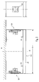
- Fig. 1 an embodiment of a medical supply device according to the invention is sketched in perspective.
- the supply device is designed to provide supply media, in particular of medical gases and / or electricity.
- the supply device may be designed to be installed or installed in a patient room of a hospital.
- Fig. 1 is the view from above obliquely on the "front" of the supply device shown, so on the side that is seen in the assembled state of a person in the room in question.
- the gases may, for example, be compressed air and / or oxygen.
- the current may be high current and / or low current.
- the weak current can be provided to provide signals, for example, for a transmission of video and / or Femseha and / or for telephoning u. s. w.
- the supply device is intended to be connected to a (in Fig. 1 not shown) wall area with (also not shown) supply lines of the supply media to be mounted.
- a wall area with (also not shown) supply lines of the supply media to be mounted.
- supply lines typically, in a patient room corresponding supply lines, so appropriate gas pipes and power lines in an area at the edge of the ceiling for further connection in the room interior.
- the supply device comprises a first vertical element 2, which is elongated and which is intended to be mounted vertically.
- the first vertical element 2 may in particular have a height of more than two meters.
- the first vertical element 2 has at least one first connection element 4 for at least one of the supply media.
- the at least one first connection element 4 can accordingly - as in Fig. 1 indicated by way of example - comprise a power socket or mains socket or a switch; but it may also or additionally comprise a low-voltage socket and / or a gas connection element.
- the at least one first connection element 4 can also each have at least one connection element of a corresponding type.
- the supply device has a second vertical element 6, which is elongate and which is intended to be mounted vertically and thereby with a horizontal distance a to the first vertical element 2.
- the second vertical element 6 may in particular have a height of more than two meters, for example the same height as the first vertical element 2.
- the second vertical element 6 has at least one second connecting element 8 for at least one of the supply media.
- the at least one second connection element 8 can otherwise be formed analogously to the at least one first connection element 4.
- the distance a is advantageously chosen so that the head of a hospital bed between the two vertical elements 2, 6 finds room.
- the distance a is greater than 1.20 meters, preferably greater than 1.50 meters. This is advantageous with respect to the space utilization of the room in question.
- the supply device has at least one first line 10 for conducting at least one of the supply media, which is conductively connected to the at least one first connection element 4.
- the at least one first line 10 can - as exemplified in Fig. 1 indicated - be a power line, but it may also or additionally include a low-voltage line and / or a gas line.
- a corresponding line may be provided as part of the at least one first line 10, which is conductively connected to the relevant connection element.
- the at least one first connection element 4 may comprise a power socket, two low-voltage sockets and two gas connections and the at least one first line 10 correspondingly a power line connected in a conductive manner to the power socket, two low-current lines which are conductively connected to the two low-voltage sockets and two Gas lines, which are conductively connected to the two gas connections.
- a gas connection is preferably not provided laterally, but at the front.
- Fig. 1 is the at least one first line 10 shown in phantom; this is intended to indicate that this line 10 or the relevant lines preferably under a - arranged in more detail below - cladding element of the first vertical element 2 is arranged, for example, in a cable channel within an aluminum profile, so that the line 10 - at fully installed supply device - from Seen from room due to the cladding element is not visible or optically laminated.
- the supply device has at least one second line 12 for conducting at least one of the supply media, which is conductively connected to the at least one second connection element 8.
- the at least one second line 12 is formed analogous to the at least one first line 4. Also, this line 12 may be optically laminated accordingly.
- the supply device has a feed and distribution unit 14 which has means for a conductive connection between the supply lines on the one hand and the at least one first line 10 and the at least one second line 12 on the other.
- the feed and distribution unit 14 may have a sub-distributor, in particular a jumper or be formed from such.
- the feed and distribution unit 14 is advantageous with the first Vertical unit 2 connected or part of the first vertical unit 2.
- the feed and distribution unit 14 is preferably optically laminated or arranged under a corresponding cladding element.
- the feed and distribution unit 14 - as in Fig. 1 indicated - arranged in an upper region of the first vertical element 2.
- the feed and distribution unit 14 is located at a location that is located in many cases - with fully assembled supply device - particularly close to the corresponding free ends of the supply lines.
- the connection of the supply device to the supply lines is generally facilitated.
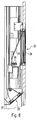
- Fig. 2 is an example of a view of a feed and distribution unit 14 - with removed trim element - shown in the form of a jumper.
- the at least one first connection element 4 comprises at least one power socket and at least one low-voltage socket, but no gas connection element.
- the sockets can be attached by means of a connector in an aluminum profile or in the panel or the cladding element.
- the at least one second connection element 8 corresponds to the at least one first line 10 has at least one power line and at least one weak current line and analogously, the at least one second line 12 also has at least one power line and at least one weak current line. In general, however, it is also possible, as already explained, to provide corresponding gas lines.
- the at least one first line 10 and the at least one second line 12 is connected to the feed and distribution unit 14 and the latter connected to the corresponding supply lines.
- the supply device is also suitable in a case in which the relevant room only has corresponding supply lines at one point, ie not both at a first location for connection to the first vertical unit and additionally at a second location for connection to the second vertical unit. So it's just a "feed-in", a "central feed” of different media required. By this feed and distribution unit 14, the installation of the supply device is thus significantly facilitated.
- the feed and distribution unit 14 comprises - as in Fig. 2 shown by way of example - connection terminals, in particular series connection terminals for the supply lines and sockets for receiving arranged on the lines 10, 12, corresponding electrical connector elements. This makes installation easier.
- the at least one first line 10 can already advantageously be connected to the feed and distribution unit 14 before installation as planned. As a result, the installation work in the room in question are further facilitated.
- the supply device has an exemplary in Fig. 1 shown cross-connection element 16, which is arranged to connect an upper region of the first vertical element 2 with an upper region of the second vertical element 6.
- a cross-connection element 16 is particularly suitable for concealing the at least one second line 12 on its section between the two vertical elements 2, 6, that is to say visually concealing it.
- the cross-connection element 16 may comprise a cladding element, which is preferably formed optically analogous to the cladding element of the first vertical element 2.
- Fig. 2 is the cladding element of the cross-connection element 16 recognizable, since only the cladding element of the first vertical element 2 is removed.
- the cladding element of the transverse connecting element 16 preferably adjoins, on the one hand, directly to a cladding element of the first vertical element 2 and, on the other hand, directly to a cladding element of the second vertical element 6.
- the cross-connection element 16 is arranged so high that the abovementioned head end of a sickbed can fit underneath.
- a hospital bed in a through the two vertical elements 2, 6 and the Cross connector 16 formed niche N push up to the wall of the room in question; This allows a particularly effective use of space.
- the supply device may have a total of more than two vertical elements 2, 6, for example - as in Fig. 1 shown - a total of three vertical elements.
- the distance corresponding to the distance a can be selected between each two adjacent vertical elements, so that in each case one head end of a hospital bed can be placed between each two adjacent vertical elements.
- the third and each further vertical element 6 ' can each be designed analogously to the first or second vertical element 2, 6.
- a transverse connecting element 16 ' may be provided, which is formed analogously to the above-mentioned transverse connecting element 16.
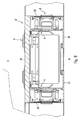
- Fig. 3 For example, a horizontal cross section through the first vertical element 2 is sketched. As an example of the at least one second connection element 8, two sockets are shown here. In the minor figure a corresponding supervision is sketched on one of the sockets.
- the first vertical element 2 has two vertical support elements 20, 22, and a cladding element 24, which is connected to the two support elements 20, 22.
- the support elements 20, 22 are preferably profile elements; they are made of aluminum, for example. By the support members 20, 22 can thus be formed a framework of the vertical element.
- the cladding element 24 is accordingly arranged on a room side R of the first vertical element 2, which is intended to point towards the center of the room or to form the front side.
- fastening elements are preferably provided on the two support elements 20, 22 for fastening the first vertical element 2 to the relevant wall.
- the support elements 20, 22 may in particular be connected to one another via connecting struts.
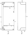
- Fig. 9 is outlined a rear view of the supply device with removed cladding elements (and without the feed and distribution unit 14). It is recognized that the vertical elements 2, 6, 6 'in each case have the two support elements 20, 22 described, which are each connected to one another via a plurality of connecting struts 28 arranged at different heights.
- the cladding element 24 may be formed for example by a panel, in particular by a wooden panel.
- the embodiment is such that the cladding element 24 can be removed without tools from the support elements 20, 22, for example by a latching or snap connection. As a result, the assembly of the supply device is further facilitated.
- the embodiment is such that a tool is required to remove the cladding elements of the support elements.
- an additional backup to prevent accidental opening - for example, by a patient -; This may be provided, for example, in particular in the area of the feed and distribution unit 14.
- a backup may be provided in the form of a castle.
- the first vertical element 2 has a width b.
- the cladding element 24 preferably extends over the entire width b.
- the width b may for example be between 25 cm and 100 cm.
- the embodiment described is particularly well suited to make vertical elements 2, 6, 6 'in different widths b , because this is only necessary to make the corresponding cladding elements 24 in the respective desired width b.
- the support members 20, 22 can be used without modifications. If necessary, only in their length correspondingly modified connecting struts 28 must be used. This is important because different hospital rooms usually have different dimensions.
- the structure described may be provided in an analogous manner in each of the vertical elements 2, 6, 6 '.
- the cross-connection element 16 may have a corresponding structure, in particular a visually analogous designed cladding element.
- a modular system for forming a corresponding supply device can be formed by means of which a simple system can be created Adjustment to the dimensions of the room in question is possible. If it is desired that one of the vertical elements 2, 6, 6 'directly adjoins a corresponding side wall of the room, closing elements in the form of angles or the like can easily be provided for this, by which a flush termination of the supply device can be achieved without much effort achieve the relevant side wall out.
- the vertical elements 2, 6, 6 'and the cross-connection elements 16, 16' can be prefabricated advantageous in each individual case, so that the installation on site in the room is particularly simple.
- the supply device can be designed in this way particularly advantageous in such a way that it meets requirements for medical products already in the prefabricated state, whereby the installation of the supply device is further significantly simplified. Also, maintenance and retrofitting are thereby generally facilitated, as this usually a review of the central feed and distribution unit 14 is required in the first place.
- Fig. 4 is a frontal view of the utility outlined.
- the configuration of the supply device can be such that a head end of a sick bed can be inserted into the niche N , which is laterally formed and bounded by the two vertical elements 2, 6 and above by the transverse connecting element 16.
- the cross-connection element 16 has at least one luminaire.
- the at least one luminaire may in particular comprise a reading light 30 with a predominantly downward or obliquely downward light output and / or a room luminaire 32 with a predominantly horizontal or obliquely upward light output.
- Fig. 5 is a section along the line B - B off Fig. 4 outlined in which the two mentioned lights 30, 32 can be seen.
- Fig. 6 shows the area around the two lights 30, 32 in more detail.
- the reading light 30 is arranged on the underside of the cross-connecting element 16.
- the bottom can be formed by an oblique covering or cladding element, for example made of aluminum, which has a light exit opening for the reading light 30, in which a preferably plane translucent cover of the reading light 30 - substantially flush with the surrounding cladding element - is arranged.
- the room lamp 32 preferably has a reflector 34 which serves or is designed to direct asymmetrically upwardly or obliquely upward a light generated by a light source 36 of the room light 32.
- the room lamp 32 has a preferably planar-shaped translucent cover 38, which is arranged at least substantially in a plane which is given by a surface of the surrounding cladding element of the cross-connection element 16.
- the supply device can be designed to extend to the ceiling of the relevant room. But it can also be provided that the height is dimensioned such that there is a small distance from the ceiling. In this case, at least one additional illuminant or an additional luminaire can be arranged at the top of the supply device, for example for the generation of an indirect illumination.
- Fig. 7 is a horizontal section along the line A - A from Fig. 4 shown and in Fig. 8 a detailed view Fig. 7 in the region of the second vertical element 6, however, the sketch applies completely analogously also to the first vertical element 2 or, if appropriate, to each further vertical element 6 '. It can be seen, inter alia, the two - shown here in a variation - supporting elements 20, 22 and the cladding element 24th
- connection element A here for example in the form of a gas connection element; However, it can also generally be a different type of connection element.
- the connection element A is attached to one of the two support elements 20, 22 or to both support elements 20, 22, but not to the cladding element 24. In the example shown, the connection element A is fixed to both support elements 20, 22 by means of anchorages V. By this type of attachment of the connection element A , the risk is reduced that by a manipulation of the connection element A, the cladding element 24 unintentionally detached from the support members 20, 22.
- connection element A on a side surface of a vertical element 2, 6 thus for example at a side facing the niche N side.
- a corresponding connecting element A can for this purpose be fastened to one of the two supporting elements 20, 22 without being fastened to the lining element 24.
- the connection element A -in the example shown in the form of a socket-can preferably be held with respect to the vertical element 2, 6 from the inside, through a hole, for example a milling in the corresponding profile side wall by means of a latching connection. This allows a reliable and easy to make connection.
- a separate guide is preferably provided for low-voltage lines, power lines and gas lines.
- low-voltage lines for example, serve in the vertical element 2, 6 inserted plastic pipes in which the respective lines are guided.
- the first and / or each further vertical element 2, 6, 6 'of the medical supply device has at least one ram protection element 40 for reducing the risk of damaging the vertical element 2, 6, 6'.
- the ram protection element 40 is preferably formed in the region of a front edge of the vertical element 2, 6, 6 ', which forms a boundary of the niche N.
- Fig. 10 For example, a horizontal cross section through a vertical element 2, 6, 6 'outlined.
- the impact protection element 40 is advantageously stably connected directly to one of the support elements 20, 22 shown here again in the variant, for example with special connection elements 42, which are arranged so that they intersect a hole in the respective support element 20, 22.
- a screw connection can be provided for this purpose.
- Fig. 11 is a section of a front view of a vertical element 2, 6, 6 'outlined, which has a ram 40.
- the ram protection element 40 is formed by a separate profile element, for example made of aluminum.
- the cladding elements 24 facing the room side R may be formed by wooden panels and the ram protection element 40 by a metal profile.
- the ram protection element 40 may be designed such that it extends only over part of the height of the vertical element 2, 6, 6 'or over the entire height.
- the Rammtikelement 40 is flush with the surrounding front panel member 24; Accordingly, it is also advantageously designed flush with the adjacent lateral, further cladding element 26.
- a lamp can be particularly advantageous to realize a subtle lighting of the room, for example, as a night or orientation light.
- the vertical element 2, 6, 6 'does not extend all the way to the bottom of the room but, a few centimeters, for example between 5 and 20 cm, is spaced from the floor.
- this luminaire can advantageously have a light emission surface facing down to the ground. A corresponding distance is also advantageous with respect to a cleaning of the floor of the room.
- the front side of a vertical unit 2, 6 need not necessarily be formed by a planar surface, optionally with the corresponding connection elements. It is also possible to provide elements through which, for example, shelves or small cabinets of the like are formed. The design of the surfaces of the panels and the choice of material for this are flexibly selectable. Preferably, it is embodiments that allow easy cleaning.
- the at the transverse modules 16, 16 'provided light exit openings of the at least one lamp or the lights 30, 32 are therefore preferably covered with transparent covers that form a flush surface with the respective surrounding cladding element.
- the supply device according to the invention is generally suitable not only for patient rooms, but can also be suitable, for example, for rooms in nursing homes or hotels.
Landscapes
- Health & Medical Sciences (AREA)
- Nursing (AREA)
- Life Sciences & Earth Sciences (AREA)
- Animal Behavior & Ethology (AREA)
- General Health & Medical Sciences (AREA)
- Public Health (AREA)
- Veterinary Medicine (AREA)
- Accommodation For Nursing Or Treatment Tables (AREA)
Description
- Die Erfindung betrifft eine medizinische Versorgungseinrichtung zur Bereitstellung von Versorgungsmedien, insbesondere von medizinischen Gasen und/oder Strom, die dafür vorgesehen ist, an einem Wandbereich mit Zufuhrleitungen der Versorgungsmedien montiert zu werden. Weiterhin betrifft die Erfindung ein längliches Vertikalelement einer derartigen Versorgungseinrichtung.
- Eine derartige Versorgungseinrichtung ist aus dem Bereich der Ausstattung von Patientenzimmern in Krankenhäusern bekannt. In der Praxis hat sich die Montage bzw. Installation solcher Versorgungseinrichtungen als vergleichsweise aufwändig herausgestellt.
- Aus der
EP 2 177 682 A2 ist ein modulares Raumsystem aus dem medizinischen Versorgungsbereich bekannt. Das System umfasst vertikale Säulenelemente mit Steckdosen und Gasauslässen. Letztere sind mit entsprechenden Versorgungsleitungen für Gase und für Strom verbunden. Zur Anbindung der Versorgungsleitungen an die entsprechenden raumseitigen Zuführungsleitungen sind ein Stromverteilungskasten und T-förmige Anschlussstücke für die Gase vorgesehen. - Aus der
DE 2 152 916 A1 ist eine Zentraleinheit für Krankenzimmer bekannt, die elektrische Leitungen sowie Gasleitungen aufweist. Die Einheit umfasst vertikale Seitenteile mit Steckdosen und Gasauslässen. Zur Anbindung an die raumseitigen Zuführungsleitungen ist ein elektrischer Anschlusskasten vorgesehen. - Der Erfindung liegt die Aufgabe zugrunde, eine entsprechende verbesserte Versorgungseinrichtung bzw. ein entsprechend verbessertes Vertikalelement für eine derartige Versorgungseinrichtung anzugeben; insbesondere soll sich die Versorgungseinrichtung besonders leicht installieren und an unterschiedliche Zimmerverhältnisse anpassen lassen.
- Diese Aufgabe wird gemäß der Erfindung mit den in dem unabhängigen Anspruch 1 genannten Gegenständen gelöst. Besondere Ausführungsformen der Erfindung sind in den abhängigen Ansprüchen angegeben.
- Gemäß der Erfindung ist eine medizinische Versorgungseinrichtung zur Bereitstellung von Versorgungsmedien, insbesondere von medizinischen Gasen und/oder Strom, vorgesehen, die dafür vorgesehen ist, an einem Wandbereich mit Zufuhrleitungen der Versorgungsmedien montiert zu werden. Die Versorgungseinrichtung weist ein erstes Vertikalelement auf, das länglich ausgebildet ist und das dafür vorgesehen ist, vertikal montiert zu werden, wobei das erste Vertikalelement wenigstens ein erstes Anschlusselement für wenigstens eines der Versorgungsmedien aufweist; weiterhin weist die Versorgungseinrichtung ein zweites Vertikalelement auf, das länglich ausgebildet ist und das dafür vorgesehen ist, vertikal und dabei mit einem horizontalen Abstand zu dem ersten Vertikalelement montiert zu werden, wobei das zweite Vertikalelement wenigstens ein zweites Anschlusselement für wenigstens eines der Versorgungsmedien aufweist. Weiterhin weist die Versorgungseinrichtung wenigstens eine erste Leitung zum Leiten wenigstens eines der Versorgungsmedien auf, die leitend mit dem wenigstens einen ersten Anschlusselement verbunden ist, sowie wenigstens eine zweite Leitung zum Leiten wenigstens eines der Versorgungsmedien, die leitend mit dem wenigstens einen zweiten Anschlusselement verbunden ist. Außerdem weist die Versorgungseinrichtung eine Einspeise- und Verteilereinheit auf, die Mittel für eine leitende Verbindung zwischen den Zufuhrleitungen einerseits und der wenigstens einen ersten Leitung und der wenigstens einen zweiten Leitung andererseits aufweist.
- Zur Anbindung der Leitungen an die Zufuhrleitungen im Rahmen der Montage bzw. Installation der Versorgungseinrichtung in dem Zimmer, das die betreffende Wand aufweist, müssen die Leitungen lediglich an einer Stelle, nämlich an der Einspeise- und Verteilereinheit mit den Zufuhrleitungen entsprechend verbunden werden. Insbesondere ist es nicht erforderlich, dass für jedes der Vertikalelemente gesonderte Zufuhrleitungen an entsprechend geeigneten Stellen zur Verfügung gestellt werden. Der Aufwand zur Montage und Installation der Versorgungseinrichtung ist hierdurch signifikant verringert.
- Vorzugsweise weist die Einspeise- und Verteilereinheit einen Unterverteiler, insbesondere einen Rangierverteiler auf. Erfindungsgemäß ist die Einspeise- und Verteilereinheit Teil des ersten Vertikalelements. In diesem Fall kann die wenigstens eine erste Leitung bereits vor der Montage der Versorgungseinrichtung vor Ort mit der Einspeise- und Verteilereinheit verbunden werden, so dass die Installation weiterhin erleichtert ist.
- Vorzugsweise weist die Versorgungseinrichtung weiterhin ein Querverbindungselement auf, das einen oberen Bereich des ersten Vertikalelements mit einem oberen Bereich des zweiten Vertikalelements verbindend angeordnet ist. Das Querverbindungselement ermöglicht eine vorteilhafte Kaschierung desjenigen Teils der Leitungen, der sich zwischen den beiden Vertikalelementen erstreckt. Hierdurch lässt sich also insbesondere die wenigstens eine zweite Leitung zwischen den beiden Vertikalelementen auf einfache Weise kaschieren. Auch kann durch das Querverbindungselement gegebenenfalls die Einspeise- und Verteilereinheit kaschiert werden, falls sich die Zufuhrleitungen an einer entsprechenden Stelle in das betreffende Zimmer hinein erstrecken.
- Vorzugsweise weist das Querverbindungselement wenigstens eine Leuchte auf. Aufgrund der Anordnung des Querverbindungselements in einem oberen Bereich zwischen den beiden Vertikalelementen eignet sich die Anordnung wenigstens einer Leuchte an bzw. in dem Querverbindungselement besonders gut. Insbesondere kann die wenigstens eine Leuchte eine Leseleuchte mit einer überwiegend nach unten bzw. nach schräg unten gerichteten Lichtabgabe aufweisen und/oder eine Raumleuchte mit einer überwiegend horizontalen bzw. nach schräg oben gerichteten Lichtabgabe. Die Raumleuchte weist dabei vorzugsweise einen Reflektor auf, der dazu dient, ein von einem Leuchtmittel der Raumleuchte erzeugtes Licht asymmetrisch nach oben bzw. nach schräg oben zu lenken.
- Vorzugsweise weist das erste Vertikalelement zwei vertikale Stützelemente auf sowie wenigstens ein Verkleidungselement, das mit einem der beiden Stützelemente oder mit beiden Stützelementen verbunden ist. Hierdurch ist eine einfach, variabel zu gestaltende und dabei stabile Konstruktion ermöglicht. Wenn das Verkleidungselement über eine Rastverbindung mit dem Stützelement bzw. mit den Stützelementen verbunden ist, ist eine besonders einfache Montage ermöglicht.
- Vorteilhaft ist das wenigstens eine erste Anschlusselement an einem der beiden Stützelemente oder an beiden Stützelementen befestigt, jedoch nicht an dem Verkleidungselement. Hierdurch lässt sich die Gefahr verringern, dass durch eine Manipulation an dem wenigstens einen ersten Anschlusselement das Verkleidungselement von den Stützelementen ungewollt gelöst wird.
- Das erste bzw. zweite Vertikalelement weist vorzugsweise wenigstens ein Rammschutzelement zur Verringerung der Gefahr einer Beschädigung des Vertikalelements auf, beispielsweise durch ein Krankenbett auf, wobei das Rammschutzelement vorzugsweise durch ein gesondertes Profilelement gebildet ist.
- In einem unteren Bereich des ersten bzw. zweiten Vertikalelements ist vorzugsweise eine Leuchte angeordnet, die zur Lichtabgabe nach unten oder nach schräg unten ausgebildet ist. Durch eine solche Leuchte lässt sich besonders vorteilhaft eine dezente Beleuchtung des Zimmers, beispielsweise als Nacht- oder Orientierungslicht realisieren.
- Die Erfindung wird im Folgenden anhand von Ausführungsbeispielen und mit Bezug auf die Zeichnungen näher erläutert. Es zeigen:
- Fig. 1
- eine perspektivische Skizze eines Ausführungsbeispiels einer erfindungsgemäßen medizinischen Versorgungseinrichtung,
- Fig. 2
- eine Ansicht eines Ausführungsbeispiels einer Einspeise- und Verteilereinheit der Versorgungseinrichtung,
- Fig. 3
- einen Horizontalschnitt durch ein erstes bzw. zweites Vertikalelement der Versorgungseinrichtung,
- Fig. 4
- eine Frontansicht der Versorgungseinrichtung,
- Fig. 5
- einen Schnitt längs der Linie B - B aus
Fig. 4 , - Fig. 6
- eine Detailansicht aus
Fig. 5 im Bereich der Leuchten, - Fig. 7
- einen Horizontalschnitt längs der Linie A - A aus
Fig. 4 , - Fig. 8
- eine Detailansicht aus
Fig. 7 im Bereich des zweiten Vertikalelements, - Fig. 9
- eine Rückansicht der Stützelemente der Versorgungseinrichtung,
- Fig. 10
- einen Horizontalschnitt eines Vertikalelements im Bereich eines Rammschutzelements und
- Fig. 11
- einen Ausschnitt aus einer Frontansicht eines Vertikalelements mit einem Rammschutzelement.
- In
Fig. 1 ist ein Ausführungsbeispiel einer erfindungsgemäßen medizinischen Versorgungseinrichtung perspektivisch skizziert. Die Versorgungseinrichtung ist zur Bereitstellung von Versorgungsmedien ausgebildet, insbesondere von medizinischen Gasen und/oder Strom. Insbesondere kann die Versorgungseinrichtung dafür vorgesehen sein, in einem Pateientenzimmer eines Krankenhauses montiert bzw. installiert zu werden. InFig. 1 ist der Blick von schräg oben auf die "Frontseite" der Versorgungseinrichtung gezeigt, also auf diejenige Seite, die im montierten Zustand von einer in dem betreffenden Zimmer befindlichen Person gesehen wird. - Bei den Gasen kann es sich beispielsweise um Druckluft und/oder Sauerstoff handeln. Bei dem Strom kann es sich um Starkstrom und/oder Schwachstrom handeln. Der Schwachstrom kann dazu vorgesehen sein, Signale zur Verfügung zu stellen, beispielsweise für eine Übertragung von Video- und/oder Femsehinformationen und/oder zum Telefonieren u. s. w.
- Die Versorgungseinrichtung ist dafür vorgesehen, an einem (in
Fig. 1 nicht gezeigten) Wandbereich mit (ebenfalls nicht gezeigten) Zufuhrleitungen der Versorgungsmedien montiert zu werden. Typischerweise ragen in einem Patientenzimmer entsprechende Zufuhrleitungen, also entsprechende Gasrohre und Stromleitungen in einem Bereich am Rand der Decke zur weiteren Verbindung in das Zimmerinnere. - Die Versorgungseinrichtung weist ein erstes Vertikalelement 2 auf, das länglich ausgebildet ist und das dafür vorgesehen ist, vertikal montiert zu werden. Das erste Vertikalelement 2 kann insbesondere eine Höhe von mehr als zwei Metern aufweisen. Das erste Vertikalelement 2 weist wenigstens ein erstes Anschlusselement 4 für wenigstens eines der Versorgungsmedien auf. Das wenigstens eine erste Anschlusselement 4 kann dementsprechend - wie in
Fig. 1 beispielhaft angedeutet - eine Starkstromsteckdose bzw. Netzsteckdose oder einen Schalter umfassen; es kann aber auch bzw. zusätzlich eine Schwachstromsteckdose umfassen und/oder ein Gasanschlusselement. Das wenigstens eine erste Anschlusselement 4 kann auch jeweils mindestens ein Anschlusselement einer entsprechenden Art aufweisen. - Weiterhin weist die Versorgungseinrichtung ein zweites Vertikalelement 6 auf, das länglich ausgebildet ist und das dafür vorgesehen ist, vertikal und dabei mit einem horizontalen Abstand a zu dem ersten Vertikalelement 2 montiert zu werden. Das zweite Vertikalelement 6 kann insbesondere eine Höhe von mehr als zwei Metern aufweisen, beispielsweise dieselbe Höhe wie das erste Vertikalelement 2. Das zweite Vertikalelement 6 weist wenigstens ein zweites Anschlusselement 8 für wenigstens eines der Versorgungsmedien auf. Das wenigstens eine zweite Anschlusselement 8 kann im Übrigen analog zu dem wenigstens einen ersten Anschlusselement 4 ausgebildet sein.
- Der Abstand a ist vorteilhaft so gewählt, dass das Kopfende eines Krankenbettes zwischen den beiden Vertikalelementen 2, 6 Platz findet. Beispielsweise kann vorgesehen sein, dass der Abstand a größer als 1,20 Meter, vorzugsweise größer als 1,50 Meter ist. Dies ist vorteilhaft mit Bezug auf die Raumausnutzung des betreffenden Zimmers.
- Weiterhin weist die Versorgungseinrichtung wenigstens eine erste Leitung 10 zum Leiten wenigstens eines der Versorgungsmedien auf, die leitend mit dem wenigstens einen ersten Anschlusselement 4 verbunden ist. Die wenigstens eine erste Leitung 10 kann - wie beispielhaft in
Fig. 1 angedeutet - eine Starkstromleitung sein, sie kann aber auch bzw. zusätzlich eine Schwachstromleitung umfassen und/oder eine Gasleitung. Insbesondere kann für jedes einzelne Anschlusselement des wenigstens einen ersten Anschlusselements 4 jeweils eine entsprechende Leitung als Teil der wenigstens einen ersten Leitung 10 vorgesehen sein, die mit dem betreffenden Anschlusselement leitend verbunden ist. Beispielsweise kann also das wenigstens eine erste Anschlusselement 4 eine Starkstromsteckdose, zwei Schwachstromsteckdosen und zwei Gasanschlüsse umfassen und die wenigstens eine erste Leitung 10 dementsprechend eine Starkstromleitung, die leitend mit der Starkstromsteckdose verbunden ist, zwei Schwachstromleitungen, die leitend mit den beiden Schwachstromsteckdosen verbunden sind und zwei Gasleitungen, die leitend mit den beiden Gasanschlüssen verbunden sind. Ein Gasanschluss ist dabei vorzugsweise nicht seitlich, sondern frontseitig vorgesehen. - In der
Fig. 1 ist die wenigstens eine erste Leitung 10 strichpunktiert gezeichnet; dies soll andeuten, dass diese Leitung 10 bzw. die betreffenden Leitungen vorzugsweise unter einem - nachfolgend noch näher beschriebenen - Verkleidungselement des ersten Vertikalelements 2 angeordnet ist, beispielsweise in einem Kabelkanal innerhalb eines Aluminiumprofils, so dass die Leitung 10 - bei fertig installierter Versorgungseinrichtung - vom Zimmer aus betrachtet aufgrund des Verkleidungselements nicht sichtbar bzw. optisch kaschiert ist. - Weiterhin weist die Versorgungseinrichtung wenigstens eine zweite Leitung 12 zum Leiten wenigstens eines der Versorgungsmedien auf, die leitend mit dem wenigstens einen zweiten Anschlusselement 8 verbunden ist. Die wenigstens eine zweite Leitung 12 ist analog ausgebildet wie die wenigstens eine erste Leitung 4. Auch diese Leitung 12 kann optisch entsprechend kaschiert sein.
- Außerdem weist die Versorgungseinrichtung eine Einspeise- und Verteilereinheit 14 auf, die Mittel für eine leitende Verbindung zwischen den Zufuhrleitungen einerseits und der wenigstens einen ersten Leitung 10 und der wenigstens einen zweiten Leitung 12 andererseits aufweist. Die Einspeise- und Verteilereinheit 14 kann einen Unterverteiler, insbesondere einen Rangierverteiler aufweisen oder aus einem solchen gebildet sein. Die Einspeise- und Verteilereinheit 14 ist vorteilhaft mit der ersten Vertikaleinheit 2 verbunden oder Teil der ersten Vertikaleinheit 2. Auch die Einspeise- und Verteilereinheit 14 ist vorzugsweise optisch kaschiert bzw. unter einem entsprechenden Verkleidungselement angeordnet.
- Vorzugsweise ist die Einspeise- und Verteilereinheit 14 - wie in
Fig. 1 angedeutet - in einem oberen Bereich des ersten Vertikalelements 2 angeordnet. Hierdurch befindet sie sich an einer Stelle, die in vielen Fällen - bei fertig montierter Versorgungseinrichtung - besonders nahe an den entsprechenden freien Enden der Zufuhrleitungen lokalisiert ist. Hierdurch ist der Anschluss der Versorgungseinrichtung an die Zufuhrleitungen im Allgemeinen erleichtert. - In
Fig. 2 ist beispielhaft eine Ansicht einer Einspeise- und Verteilereinheit 14 - bei abgenommenem Verkleidungselement - in Form eines Rangierverteilers gezeigt. In dem gezeigten Beispiel umfasst das wenigstens eine erste Anschlusselement 4 wenigstens eine Starkstromsteckdose und wenigstens eine Schwachstromsteckdose, jedoch kein Gasanschlusselement. Die Steckdosen können dabei mittels eines Steckverbinders in einem Aluminiumprofil bzw. in der Verkleidung bzw. dem Verkleidungselement angebracht sein. Analoges gilt für das wenigstens eine zweite Anschlusselement 8. Dementsprechend weist die wenigstens eine erste Leitung 10 wenigstens eine Starkstromleitung und wenigstens eine Schwachstromleitung auf und analog weist die wenigstens eine zweite Leitung 12 ebenfalls wenigstens eine Starkstromleitung und wenigstens eine Schwachstromleitung auf. Im Allgemeinen können aber - wie bereits ausgeführt - zusätzlich auch entsprechende Gasleitungen vorgesehen sein. - Zur Anbindung der Leitungen 10, 12 im Rahmen der Installation der Versorgungseinrichtung wird die wenigstens eine erste Leitung 10 und die wenigstens eine zweite Leitung 12 mit der Einspeise- und Verteilereinheit 14 verbunden und Letztere an die entsprechenden Zufuhrleitungen angeschlossen. Insbesondere eignet sich die Versorgungseinrichtung auch in einem Fall, in dem das betreffende Zimmer lediglich an einer Stelle entsprechende Zufuhrleitungen aufweist, also nicht sowohl an einer ersten Stelle zur Anbindung an die erste Vertikaleinheit und zusätzlich an einer zweiten Stelle zur Anbindung an die zweite Vertikaleinheit. Es ist also lediglich eine "Einspeise-Stelle", eine "zentrale Einspeisung" der unterschiedlichen Medien erforderlich. Durch diese Einspeise- und Verteilereinheit 14 ist die Installation der Versorgungseinrichtung somit signifikant erleichtert.
- Vorteilhaft umfasst die Einspeise- und Verteilereinheit 14 - wie in
Fig. 2 beispielhaft gezeigt - Anschlussklemmen, insbesondere Reihenanschlussklemmen für die Zufuhrleitungen sowie Steckbuchsen zur Aufnahme von an den Leitungen 10, 12 angeordneten, entsprechenden elektrischen Steckverbindungselementen. Hierdurch ist die Installation weiterhin erleichtert. - Wenn die Einspeise- und Verteilereinheit 14 Teil des ersten Vertikalelements 2 ist oder mit dem ersten Vertikalelement 2 mechanisch verbunden ist, kann die wenigstens eine erste Leitung 10 bereits vorteilhaft vor der Installation wie vorgesehen mit der Einspeise- und Verteilereinheit 14 verbunden werden. Hierdurch sind die Installationsarbeiten im betreffenden Zimmer weitergehend erleichtert.
- Weiterhin vorteilhaft weist die Versorgungseinrichtung ein beispielhaft in
Fig. 1 gezeigtes Querverbindungselement 16 auf, das einen oberen Bereich des ersten Vertikalelements 2 mit einem oberen Bereich des zweiten Vertikalelements 6 verbindend angeordnet ist. Ein solches Querverbindungselement 16 eignet sich besonders dazu, die wenigstens eine zweite Leitung 12 auf ihrem Abschnitt zwischen den beiden Vertikalelementen 2, 6 zu verdecken, also optisch zu kaschieren. Hierzu kann das Querverbindungselement 16 ein Verkleidungselement aufweisen, das vorzugsweise optisch analog zu dem Verkleidungselement des ersten Vertikalelements 2 ausgebildet ist. InFig. 2 ist das Verkleidungselement des Querverbindungselements 16 erkennbar, da lediglich das Verkleidungselement des ersten Vertikalelements 2 abgenommen ist. Vorzugsweise grenzt das Verkleidungselement des Querverbindungselements 16 einerseits unmittelbar an ein Verkleidungselement des ersten Vertikalelements 2 und andererseits unmittelbar an ein Verkleidungselement des zweiten Vertikalelements 6. - Vorzugsweise ist das Querverbindungselement 16 so hoch angeordnet, dass das oben genannte Kopfende eines Krankenbetts darunter Platz findet. Auf diese Weise lässt sich ein Krankenbett in eine durch die beiden Vertikalelemente 2, 6 und das Querverbindungselement 16 gebildete Nische N bis an die Wand des betreffenden Zimmers hinein schieben; dies ermöglicht eine besonders effektive Raumausnutzung.
- Die Versorgungseinrichtung kann insgesamt mehr als zwei Vertikalelemente 2, 6 aufweisen, beispielsweise - wie in
Fig. 1 gezeigt - insgesamt drei Vertikalelemente. Dabei kann zwischen jeweils zwei benachbarten Vertikalelementen der Abstand entsprechend dem Abstand a gewählt sein, so dass also jeweils ein Kopfende eines Krankenbetts zwischen jeweils zwei benachbarten Vertikalelementen Platz finden kann. Das dritte und jedes weitere Vertikalelement 6' kann jeweils analog zu dem ersten bzw. zweiten Vertikalelement 2, 6 ausgebildet sein. Weiterhin analog kann zwischen zwei benachbarten Vertikalelementen jeweils ein Querverbindungselement 16' vorgesehen sein, das analog zu dem oben genannten Querverbindungselement 16 ausgebildet ist. - In
Fig. 3 ist beispielhaft ein horizontaler Querschnitt durch das erste Vertikalelement 2 skizziert. Als Beispiel für das wenigstens eine zweite Anschlusselement 8 sind hier zwei Steckdosen gezeigt. In der Nebenfigur ist eine entsprechende Aufsicht auf eine der Steckdosen skizziert. - Vorzugsweise weist das erste Vertikalelement 2 zwei vertikale Stützelemente 20, 22 auf, sowie ein Verkleidungselement 24, das mit den beiden Stützelementen 20, 22 verbunden ist. Die Stützelemente 20, 22 sind vorzugsweise Profilelemente; sie bestehen beispielsweise aus Aluminium. Durch die Stützelemente 20, 22 kann also ein Gerüst des Vertikalelements gebildet sein.
- Das Verkleidungselement 24 ist dementsprechend auf einer Raumseite R des ersten Vertikalelements 2 angeordnet, die dafür vorgesehen ist, zur Zimmermitte hin zu weisen, bzw. die Frontseite zu bilden. Auf der gegenüberliegenden Wandseite W, die dafür vorgesehen ist, zu der Wand des Zimmers zu weisen, sind vorzugsweise Befestigungselemente an den beiden Stützelementen 20, 22 zur Befestigung des ersten Vertikalelements 2 an der betreffenden Wand vorgesehen. Die Stützelemente 20, 22 können insbesondere über Verbindungsstreben miteinander verbunden sein. In
Fig. 9 ist eine Rückansicht der Versorgungseinrichtung bei abgenommenen Verkleidungselementen (und ohne die Einspeise- und Verteilereinheit 14) skizziert. Man erkannt, dass die Vertikalelemente 2, 6, 6' jeweils die zwei beschriebenen Stützelemente 20, 22 aufweisen, die jeweils über mehrere, in unterschiedlichen Höhen angeordnete Verbindungsstreben 28 miteinander verbunden sind. - Das Verkleidungselement 24 kann beispielsweise durch ein Paneel, insbesondere durch ein Holzpaneel gebildet sein. Vorzugsweise ist die Ausgestaltung derart, dass das Verkleidungselement 24 ohne Werkzeug von den Stützelementen 20, 22 entfernt werden kann, beispielsweise durch eine Rast- oder Schnappverbindung. Hierdurch ist die Montage der Versorgungseinrichtung weitergehend erleichtert. Es kann aber auch vorgesehen sein, dass die Ausgestaltung derart ist, dass zum Entfernen der Verkleidungselemente von den Stützelementen ein Werkzeug erforderlich ist. Es kann auch eine zusätzliche Sicherung vorgesehen sein, um ein ungewolltes Öffnen - beispielsweise durch einen Patienten - zu verhindern; dies kann beispielsweise insbesondere im Bereich der Einspeise- und Verteilereinheit 14 vorgesehen sein. Hier kann beispielsweise eine Sicherung in Form eines Schlosses vorgesehen sein.
- Wie in
Fig. 3 bezeichnet, weist das erste Vertikalelement 2 eine Breite b auf. Das Verkleidungselement 24 erstreckt sich vorzugsweise über die gesamte Breite b. Die Breite b kann beispielsweise zwischen 25 cm und 100 cm betragen. Die beschriebene Ausgestaltung ist besonders gut geeignet, um Vertikalelemente 2, 6, 6' in unterschiedlichen Breiten b zu gestalten, denn es ist hierzu lediglich erforderlich, die entsprechenden Verkleidungselemente 24 in der jeweils gewünschten Breite b zu gestalten. Die Stützelemente 20, 22 können dabei ohne Modifikationen verwendet werden. Gegebenenfalls müssen lediglich in ihrer Länge entsprechend modifizierte Verbindungsstreben 28 verwendet werden. Dies ist von Bedeutung, da unterschiedliche Krankenzimmer in der Regel unterschiedliche Abmessungen haben. - Natürlich kann der beschriebene Aufbau bei jedem der Vertikalelemente 2, 6, 6' in analoger Weise vorgesehen sein. Auch das Querverbindungselement 16 kann einen entsprechenden Aufbau aufweisen, insbesondere ein optisch analog gestaltetes Verkleidungselement.
- Durch diese Ausgestaltung lässt sich sozusagen ein modulares System zur Bildung einer entsprechenden Versorgungseinrichtung bilden, durch das eine einfache Anpassung an die Maße des betreffenden Zimmers ermöglicht ist. Falls gewünscht ist, dass eines der Vertikalelemente 2, 6, 6' unmittelbar an eine entsprechende Seitenwand des Zimmers angrenzt, können hierzu in einfacher Weise Abschlusselemente in Form von Winkeln oder dergleichen vorgesehen sein, durch welche sich ohne großen Aufwand ein bündiger Abschluss der Versorgungseinrichtung zu der betreffenden Seitenwand hin erzielen lässt. Die Vertikalelemente 2, 6, 6' und die Querverbindungselemente 16, 16' können sich in jedem Einzelfall vorteilhaft vorkonfektionieren lassen, so dass die Installation vor Ort im Zimmer besonders einfach ist. Die Versorgungseinrichtung kann auf diese Weise besonders vorteilhaft derart gestaltet sein, dass sie Anforderungen an medizinische Produkte bereits im vorkonfektionierten Zustand erfüllt, wodurch die Installation der Versorgungseinrichtung weiterhin deutlich vereinfacht ist. Auch Wartungsarbeiten und Nachrüstbarkeit sind hierdurch im Allgemeinen erleichtert, da hierzu in der Regel in erster Linie eine Überprüfung der zentralen Einspeise- und Verteilereinheit 14 erforderlich ist.
- In
Fig. 4 ist eine Frontalansicht der Versorgungseinrichtung skizziert. Insbesondere kann - wie bereits erwähnt - die Ausgestaltung der Versorgungseinrichtung derart sein, dass ein Kopfende eines Krankenbetts in die Nische N eingeschoben werden kann, die seitlich durch die beiden Vertikalelemente 2, 6 und oben durch das Querverbindungselement 16 gebildet und begrenzt ist. - Besonders in diesem Fall ist es vorteilhaft, wenn das Querverbindungselement 16 wenigstens eine Leuchte aufweist. Die wenigstens eine Leuchte kann insbesondere eine Leseleuchte 30 mit einer überwiegend nach unten bzw. nach schräg unten gerichteten Lichtabgabe umfassen und/oder eine Raumleuchte 32 mit einer überwiegend horizontalen bzw. nach schräg oben gerichteten Lichtabgabe.
- In
Fig. 5 ist ein Schnitt längs der Linie B - B ausFig. 4 skizziert, in dem die beiden genannten Leuchten 30, 32 zu erkennen sind.Fig. 6 zeigt den Bereich um die beiden Leuchten 30, 32 detaillierter. Vorzugsweise ist die Leseleuchte 30 an der Unterseite des Querverbindungselements 16 angeordnet. Die Unterseite kann durch ein schräges Abdeck- bzw. Verkleidungselement, beispielsweise aus Aluminium, gebildet sein, das eine Lichtaustrittsöffnung für die Leseleuchte 30 aufweist, in der eine vorzugsweise plane lichtdurchlässige Abdeckung der Leseleuchte 30 - im Wesentlichen bündig mit dem umgebenden Verkleidungselement - angeordnet ist. - Die Raumleuchte 32 weist vorzugsweise einen Reflektor 34 auf, der dazu dient bzw. dazu ausgebildet ist, ein von einem Leuchtmittel 36 der Raumleuchte 32 erzeugtes Licht asymmetrisch nach oben bzw. nach schräg oben zu lenken. Vorteilhaft weist die Raumleuchte 32 eine vorzugsweise plan gestaltete lichtdurchlässige Abdeckung 38 auf, die zumindest im Wesentlichen in einer Ebene angeordnet ist, die durch eine Oberfläche des umgebenden Verkleidungselements des Querverbindungselements 16 gegeben ist.
- Die Versorgungseinrichtung kann dazu ausgebildet sein, sich bis an die Decke des betreffenden Zimmers hin zu erstrecken. Es kann aber auch vorgesehen sein, dass die Höhe derart bemessen ist, dass ein geringer Abstand zu Decke besteht. In diesem Fall kann an der Oberseite der Versorgungseinrichtung noch wenigstens ein zusätzliches Leuchtmittel bzw. eine zusätzliche Leuchte angeordnet sein, beispielsweise für die Erzeugung einer indirekten Beleuchtung.
- In
Fig. 7 ist ein Horizontalschnitt längs der Linie A - A ausFig. 4 gezeigt und inFig. 8 eine Detailansicht ausFig. 7 im Bereich des zweiten Vertikalelements 6. Die Skizze gilt jedoch völlig analog auch für das erste Vertikalelement 2 bzw. gegebenenfalls für jedes weitere Vertikalelement 6'. Man erkennt unter anderem die beiden - hier in einer Variation gezeigten - Stützelemente 20, 22 und das Verkleidungselement 24. - Das Vertikalelement 6 weist ein Anschlusselement A auf, hier beispielsweise in Form eines Gasanschlusselements; es kann sich jedoch allgemein auch um ein andersartiges Anschlusselement handeln. Das Anschlusselement A ist an einem der beiden Stützelemente 20, 22 oder an beiden Stützelementen 20, 22 befestigt, jedoch nicht an dem Verkleidungselement 24. Im gezeigten Beispiel ist das Anschlusselement A an beiden Stützelementen 20, 22 durch Verankerungen V fixiert. Durch diese Art der Befestigung des Anschlusselements A ist die Gefahr verringert, dass sich durch eine Manipulation an dem Anschlusselement A das Verkleidungselement 24 ungewollt von den Stützelementen 20, 22 ablöst.
- Analoges gilt mit Bezug auf eine Befestigung eines entsprechenden Anschlusselementes A an einer Seitenfläche eines Vertikalelements 2, 6 also beispielsweise an einer zu der Nische N hin weisenden Seite. Wie in
Fig. 3 gezeigt, kann ein entsprechendes Anschlusselement A hierzu an einem der beiden Stützelemente 20, 22 befestigt sein, ohne an dem Verkleidungselement 24 befestigt zu sein. Das Anschlusselement A - im gezeigten Beispiel in Form einer Steckdose - kann vorzugsweise mit Bezug auf das Vertikalelement 2, 6 von innen, durch ein Loch, beispielsweise eine Fräsung in der entsprechenden Profilseitenwand hindurch mittels einer Rastverbindung gehaltert sein. Hierdurch ist eine zuverlässige und dabei leicht herzustellende Verbindung ermöglicht. - Innerhalb eines Vertikalelements 2, 6 ist vorzugsweise eine getrennte Führung für Schwachstromleitungen, Starkstromleitungen und Gasleitungen vorgesehen. Hierzu können beispielsweise in das Vertikalelement 2, 6 eingeschobene Kunststoffrohre dienen, in denen die jeweiligen Leitungen geführt sind.
- Vorzugsweise weist das erste und/oder jedes weitere Vertikalelements 2, 6, 6' der medizinischen Versorgungseinrichtung wenigstens ein Rammschutzelement 40 zur Verringerung der Gefahr einer Beschädigung des Vertikalelements 2, 6, 6' auf. Eine derartige Beschädigung könnte beispielsweise durch ein Krankenbett oder dergleichen verursacht sein. Dementsprechend ist das Rammschutzelement 40 vorzugsweise im Bereich einer frontseitigen Kante des Vertikalelements 2, 6, 6' ausgebildet, die eine Begrenzung der Nische N bildet.
- In
Fig. 10 ist beispielhaft ein horizontaler Querschnitt durch ein Vertikalelement 2, 6, 6' skizziert. Wie gezeigt, ist das Rammschutzelement 40 vorteilhaft stabil unmittelbar mit einem der - hier wieder in der Variante gezeigten - Stützelemente 20, 22 verbunden, beispielsweise mit speziellen Verbindungselementen 42, die ein Loch in dem betreffenden Stützelement 20, 22 durchgreifend angeordnet sind. Beispielsweise kann hierfür eine Schraubverbindung vorgesehen sein. InFig. 11 ist ein Ausschnitt einer Frontansicht eines Vertikalelements 2, 6, 6' skizziert, das einen Rammschutz 40 aufweist. - Vorzugsweise ist das Rammschutzelement 40 durch ein gesondertes Profilelement, beispielsweise aus Aluminium, gebildet. Insbesondere können die Verkleidungselemente 24, die zur Zimmerseite R hin weisen, durch Holzpaneele gebildet sein und das Rammschutzelement 40 durch ein Metallprofl. Das Rammschutzelement 40 kann derart gestaltet sein, dass es sich lediglich über einen Teil der Höhe des Vertikalelements 2, 6, 6' erstreckt oder über die gesamte Höhe hinweg. Weiterhin vorzugsweise ist das Rammschutzelement 40 flächenbündig mit dem umgebenden frontseitigen Verkleidungselement 24 ausgebildet; entsprechend ist es auch vorteilhaft flächenbündig mit dem angrenzenden seitlichen, weiteren Verkleidungselement 26 gestaltet.
- Das Vertikalelement 2, 6, 6' kann weiterhin vorzugsweise in einem unteren Bereich eine (in den Figuren nicht gezeigte) weitere Leuchte aufweisen, die zur Lichtabgabe nach unten oder nach schräg unten ausgebildet ist. Durch eine solche Leuchte lässt sich besonders vorteilhaft eine dezente Beleuchtung des Zimmers, beispielsweise als Nacht- oder Orientierungslicht realisieren. Vorteilhaft kann vorgesehen sein, dass sich das Vertikalelement 2, 6, 6' nicht ganz bis zum Boden des Zimmers erstreckt sondern, einige Zentimeter, beispielsweise zwischen 5 und 20 cm vom Boden beabstandet ist. In diesem Fall kann diese Leuchte vorteilhaft eine nach unten zum Boden weisende Lichtabgabefläche aufweisen. Ein entsprechender Abstand ist auch mit Bezug auf eine Reinigung des Bodens des Zimmers vorteilhaft.
- Die Frontseite einer Vertikaleinheit 2, 6 muss nicht notwendigerweise durch eine plane Oberfläche, gegebenenfalls mit den entsprechenden Anschlusselementen, gebildet sein. Es besteht auch die Möglichkeit, Elemente vorzusehen, durch welche beispielsweise Regale oder kleine Schränkchen der dergleichen gebildet sind. Die Gestaltung der Flächen der Paneele und die Wahl des Materials hierfür sind flexibel wählbar. Vorzugsweise handelt es sich um Ausführungen, welche ein einfaches Reinigen ermöglichen. Insbesondere auch die an den Quermodulen 16, 16' vorgesehenen Lichtaustrittsöffnungen der wenigstens einen Leuchte bzw. der Leuchten 30, 32 sind deshalb vorzugsweise mit transparenten Abdeckungen abgedeckt, die eine bündige Oberfläche mit dem jeweils umgebenden Verkleidungselement bilden.
- Die erfindungsgemäße Versorgungseinrichtung eignet sich im Allgemeinen nicht nur für Patientenzimmer, sondern kann sich beispielsweise auch für Zimmer in Pflegeheimen oder Hotels eignen.
Claims (11)
- Medizinische Versorgungseinrichtung zur Bereitstellung von Versorgungsmedien, insbesondere von medizinischen Gasen und Strom, wobei die Versorgungseinrichtung dafür vorgesehen ist, an einem Wandbereich mit Zufuhrleitungen der Versorgungsmedien montiert zu werden, aufweisend- ein erstes Vertikalelement (2), das länglich ausgebildet ist und dafür vorgesehen ist, vertikal montiert zu werden, wobei das erste Vertikalelement (2) wenigstens ein erstes Anschlusselement (4) für wenigstens eines der Versorgungsmedien aufweist,- ein zweites Vertikalelement (6), das länglich ausgebildet ist und dafür vorgesehen ist, vertikal und dabei mit einem horizontalen Abstand (a) zu dem ersten Vertikalelement (2) montiert zu werden, wobei das zweite Vertikalelement (6) wenigstens ein zweites Anschlusselement (8) für wenigstens eines der Versorgungsmedien aufweist,- wenigstens eine erste Leitung (10) zum Leiten von Strom, die leitend mit dem wenigstens einen ersten Anschlusselement (4) verbunden ist,- wenigstens eine zweite Leitung (12) zum Leiten von Gas, die leitend mit dem wenigstens einen zweiten Anschlusselement (8) verbunden ist,- eine Einspeise- und Verteilereinheit (14), die Mittel für eine leitende Verbindung zwischen den Zufuhrleitungen einerseits und der wenigstens einen ersten Leitung (10) und der wenigstens einen zweiten Leitung (12) andererseits aufweist,dadurch gekennzeichnet,
dass die Einspeise- und Verteilereinheit (14) Teil des ersten Vertikalelements (2) ist. - Medizinische Versorgungseinrichtung nach Anspruch 1,
bei der die Einspeise- und Verteilereinheit (14) einen Unterverteiler, insbesondere einen Rangierverteiler aufweist. - Medizinische Versorgungseinrichtung nach Anspruch 1 oder 2,
weiterhin aufweisend- ein Querverbindungselement (16), das einen oberen Bereich des ersten Vertikalelements (2) mit einem oberen Bereich des zweiten Vertikalelements (6) verbindend angeordnet ist. - Medizinische Versorgungseinrichtung nach Anspruch 3,
bei der das Querverbindungselement (16) wenigstens eine Leuchte (30, 32) aufweist. - Medizinische Versorgungseinrichtung nach Anspruch 4,
bei der die wenigstens eine Leuchte eine Leseleuchte (30) mit einer überwiegend nach unten bzw. nach schräg unten gerichteten Lichtabgabe aufweist. - Medizinische Versorgungseinrichtung nach Anspruch 4 oder 5,
bei der die wenigstens eine Leuchte eine Raumleuchte (32) mit einer überwiegend horizontalen bzw. nach schräg oben gerichteten Lichtabgabe aufweist. - Medizinische Versorgungseinrichtung nach Anspruch 6,
bei der die Raumleuchte (32) einen Reflektor (34) aufweist, der dazu dient, ein von einem Leuchtmittel (36) der Raumleuchte (32) erzeugtes Licht asymmetrisch nach oben bzw. nach schräg oben zu lenken. - Medizinische Versorgungseinrichtung nach einem der vorhergehenden Ansprüche,
bei der das erste Vertikalelement (2) zwei vertikale Stützelemente (20, 22) aufweist sowie wenigstens ein Verkleidungselement (24), das mit einem der beiden Stützelemente (20, 22) oder mit beiden Stützelementen (20, 22), vorzugsweise über eine Rastverbindung, verbunden ist. - Medizinische Versorgungseinrichtung nach Anspruch 8,
bei der das wenigstens eine erste Anschlusselement (4, A) an einem der beiden Stützelemente (20, 22) oder an beiden Stützelementen (20, 22) befestigt ist, jedoch nicht an dem Verkleidungselement (24). - Medizinische Versorgungseinrichtung nach einem der vorhergehenden Ansprüche, weiterhin aufweisend- wenigstens ein Rammschutzelement (40) zur Verringerung der Gefahr einer Beschädigung des ersten und/oder des zweiten Vertikalelements (2, 6, 6'), beispielsweise durch ein Krankenbett, wobei das Rammschutzelement (40) vorzugsweise durch ein gesondertes Profilelement gebildet ist.
- Medizinische Versorgungseinrichtung nach einem der vorhergehenden Ansprüche, weiterhin aufweisend- eine Leuchte in einem unteren Bereich des ersten oder des zweiten Vertikalelements (2, 6, 6'), die zur Lichtabgabe nach unten oder nach schräg unten ausgebildet ist.
Applications Claiming Priority (1)
| Application Number | Priority Date | Filing Date | Title |
|---|---|---|---|
| DE201110078874 DE102011078874A1 (de) | 2011-07-08 | 2011-07-08 | Medizinische Versorgungseinrichtung |
Publications (2)
| Publication Number | Publication Date |
|---|---|
| EP2543352A1 EP2543352A1 (de) | 2013-01-09 |
| EP2543352B1 true EP2543352B1 (de) | 2016-02-03 |
Family
ID=46420017
Family Applications (1)
| Application Number | Title | Priority Date | Filing Date |
|---|---|---|---|
| EP12175120.0A Not-in-force EP2543352B1 (de) | 2011-07-08 | 2012-07-05 | Medizinische Versorgungseinrichtung |
Country Status (2)
| Country | Link |
|---|---|
| EP (1) | EP2543352B1 (de) |
| DE (1) | DE102011078874A1 (de) |
Families Citing this family (1)
| Publication number | Priority date | Publication date | Assignee | Title |
|---|---|---|---|---|
| US9237979B2 (en) * | 2011-04-11 | 2016-01-19 | Hill-Rom Services, Inc. | Gas distribution assembly |
Family Cites Families (9)
| Publication number | Priority date | Publication date | Assignee | Title |
|---|---|---|---|---|
| US3660591A (en) * | 1970-10-26 | 1972-05-02 | Hill Rom Co Inc | Hospital in-patient service core module |
| DE3106255A1 (de) * | 1981-02-20 | 1982-10-21 | Zumtobel GmbH & Co, 8990 Lindau | Kombinierte anschlusseinrichtung fuer verschiedenartige ver- und entsorgungssysteme |
| US4821470A (en) * | 1988-06-17 | 1989-04-18 | Hill-Rom Company, Inc. | Head wall for hospital bed |
| US4905433A (en) * | 1988-08-29 | 1990-03-06 | Hospital Systems, Inc. | Hospital head wall system |
| DE19514590C1 (de) * | 1995-04-20 | 1996-06-05 | Draegerwerk Ag | Versorgungseinheit |
| DE102004030799A1 (de) * | 2004-06-25 | 2006-01-19 | Zumtobel Staff Gmbh | Versorgungseinrichtung zur Bereitstellung von Versorgungsmedien |
| DE202005016891U1 (de) * | 2005-10-27 | 2007-03-01 | Zumtobel Lighting Gmbh | Versorgungseinrichtung zur Bereitstellung von Versorgungsmedien und Beleuchtungseinheit hierfür |
| US8640391B2 (en) * | 2008-10-16 | 2014-02-04 | Hill-Rom Services, Inc. | Modular architectural room system |
| DE102009020726A1 (de) * | 2009-05-11 | 2010-11-25 | Wesemann Gmbh & Co. Kg | Versorgungssystem zum Bereitstellen einer Medienversorgung |
-
2011
- 2011-07-08 DE DE201110078874 patent/DE102011078874A1/de not_active Withdrawn
-
2012
- 2012-07-05 EP EP12175120.0A patent/EP2543352B1/de not_active Not-in-force
Also Published As
| Publication number | Publication date |
|---|---|
| DE102011078874A1 (de) | 2013-01-10 |
| EP2543352A1 (de) | 2013-01-09 |
Similar Documents
| Publication | Publication Date | Title |
|---|---|---|
| DE3541017C2 (de) | Versorgungswand für medizinische Zwecke | |
| EP2220965B1 (de) | Trägerprofilschiene und Präsentationssystem mit einer solchen | |
| EP2360330B1 (de) | Leistenverbinder | |
| DE2152916A1 (de) | Zentraleinheit | |
| DE102014105855B4 (de) | Schachtbeleuchtungseinrichtung mit bandförmig angeordneten Leuchtdioden, welche gruppenweise parallel geschaltet sind | |
| WO2013171148A1 (de) | Tragschiene zur halterung und stromversorgung mehrerer leuchtmodule, sowie lichtbandsystem mit einer solchen tragschiene | |
| DE102013104470B4 (de) | Regalsystem mit Beleuchtung | |
| EP2093479A1 (de) | Aufhängevorrichtung mit einer horizontal anzuordnenden Trägerschiene | |
| EP0739618B1 (de) | Versorgungseinheit für Krankenzimmer | |
| EP2543352B1 (de) | Medizinische Versorgungseinrichtung | |
| EP2248504A1 (de) | Medizinische Versorgungseinheit mit Einbaumodulen | |
| DE10061709A1 (de) | Schrank der elektrischen Hausinstallation | |
| EP2770127B1 (de) | Montageeinrichtung für einen Sanitärkörper | |
| EP1912302A2 (de) | Einrichtung zum Anschließen von Arbeitsplätzen an ein Energie-, Daten- und/oder Kommunikationsnetz sowie Träger- und Montagekanal für eine solche Einrichtung | |
| EP2669572B1 (de) | Versorgungseinheit mit einer Leuchtenanordnung | |
| EP3853522B1 (de) | System zum anbau an eine abgehängte stromschiene sowie verfahren zum anbau des systems an eine stromschiene | |
| DE20121189U1 (de) | Einrichtung zum Installieren von Versorgungsleitungen | |
| EP1096629A1 (de) | Versorgungseinheit | |
| EP1612901B1 (de) | Versorgungseinrichtung zur Bereitstellung von Versorgungsmedien | |
| EP1297810B1 (de) | Medizinische Versorgungseinheiten | |
| DE1690171C3 (de) | Kombinierte Anschlusseinrichtung fur verschiedenartige Versorgungssysteme | |
| EP0407652A2 (de) | Aufbauwand mit Entnahmeeinrichtungen für die Intensivmedizin | |
| EP2262069A2 (de) | Vorrichtung für die Medien- und Energieversorgung | |
| AT525498B1 (de) | Steckbares Beleuchtungssystem für die Pflanzenaufzucht | |
| DE102010013768B4 (de) | Küchenmodul |
Legal Events
| Date | Code | Title | Description |
|---|---|---|---|
| PUAI | Public reference made under article 153(3) epc to a published international application that has entered the european phase |
Free format text: ORIGINAL CODE: 0009012 |
|
| AK | Designated contracting states |
Kind code of ref document: A1 Designated state(s): AL AT BE BG CH CY CZ DE DK EE ES FI FR GB GR HR HU IE IS IT LI LT LU LV MC MK MT NL NO PL PT RO RS SE SI SK SM TR |
|
| AX | Request for extension of the european patent |
Extension state: BA ME |
|
| 17P | Request for examination filed |
Effective date: 20130704 |
|
| RBV | Designated contracting states (corrected) |
Designated state(s): AL AT BE BG CH CY CZ DE DK EE ES FI FR GB GR HR HU IE IS IT LI LT LU LV MC MK MT NL NO PL PT RO RS SE SI SK SM TR |
|
| GRAP | Despatch of communication of intention to grant a patent |
Free format text: ORIGINAL CODE: EPIDOSNIGR1 |
|
| INTG | Intention to grant announced |
Effective date: 20150922 |
|
| GRAS | Grant fee paid |
Free format text: ORIGINAL CODE: EPIDOSNIGR3 |
|
| GRAA | (expected) grant |
Free format text: ORIGINAL CODE: 0009210 |
|
| AK | Designated contracting states |
Kind code of ref document: B1 Designated state(s): AL AT BE BG CH CY CZ DE DK EE ES FI FR GB GR HR HU IE IS IT LI LT LU LV MC MK MT NL NO PL PT RO RS SE SI SK SM TR |
|
| REG | Reference to a national code |
Ref country code: GB Ref legal event code: FG4D Free format text: NOT ENGLISH |
|
| REG | Reference to a national code |
Ref country code: AT Ref legal event code: REF Ref document number: 773315 Country of ref document: AT Kind code of ref document: T Effective date: 20160215 Ref country code: CH Ref legal event code: EP |
|
| REG | Reference to a national code |
Ref country code: IE Ref legal event code: FG4D Free format text: LANGUAGE OF EP DOCUMENT: GERMAN |
|
| REG | Reference to a national code |
Ref country code: DE Ref legal event code: R096 Ref document number: 502012005847 Country of ref document: DE |
|
| REG | Reference to a national code |
Ref country code: CH Ref legal event code: NV Representative=s name: WEINMANN ZIMMERLI, CH |
|
| REG | Reference to a national code |
Ref country code: LT Ref legal event code: MG4D Ref country code: NL Ref legal event code: MP Effective date: 20160203 |
|
| REG | Reference to a national code |
Ref country code: FR Ref legal event code: PLFP Year of fee payment: 5 |
|
| PG25 | Lapsed in a contracting state [announced via postgrant information from national office to epo] |
Ref country code: IT Free format text: LAPSE BECAUSE OF FAILURE TO SUBMIT A TRANSLATION OF THE DESCRIPTION OR TO PAY THE FEE WITHIN THE PRESCRIBED TIME-LIMIT Effective date: 20160203 Ref country code: NO Free format text: LAPSE BECAUSE OF FAILURE TO SUBMIT A TRANSLATION OF THE DESCRIPTION OR TO PAY THE FEE WITHIN THE PRESCRIBED TIME-LIMIT Effective date: 20160503 Ref country code: GR Free format text: LAPSE BECAUSE OF FAILURE TO SUBMIT A TRANSLATION OF THE DESCRIPTION OR TO PAY THE FEE WITHIN THE PRESCRIBED TIME-LIMIT Effective date: 20160504 Ref country code: FI Free format text: LAPSE BECAUSE OF FAILURE TO SUBMIT A TRANSLATION OF THE DESCRIPTION OR TO PAY THE FEE WITHIN THE PRESCRIBED TIME-LIMIT Effective date: 20160203 Ref country code: ES Free format text: LAPSE BECAUSE OF FAILURE TO SUBMIT A TRANSLATION OF THE DESCRIPTION OR TO PAY THE FEE WITHIN THE PRESCRIBED TIME-LIMIT Effective date: 20160203 Ref country code: HR Free format text: LAPSE BECAUSE OF FAILURE TO SUBMIT A TRANSLATION OF THE DESCRIPTION OR TO PAY THE FEE WITHIN THE PRESCRIBED TIME-LIMIT Effective date: 20160203 |
|
| PG25 | Lapsed in a contracting state [announced via postgrant information from national office to epo] |
Ref country code: IS Free format text: LAPSE BECAUSE OF FAILURE TO SUBMIT A TRANSLATION OF THE DESCRIPTION OR TO PAY THE FEE WITHIN THE PRESCRIBED TIME-LIMIT Effective date: 20160603 Ref country code: LT Free format text: LAPSE BECAUSE OF FAILURE TO SUBMIT A TRANSLATION OF THE DESCRIPTION OR TO PAY THE FEE WITHIN THE PRESCRIBED TIME-LIMIT Effective date: 20160203 Ref country code: NL Free format text: LAPSE BECAUSE OF FAILURE TO SUBMIT A TRANSLATION OF THE DESCRIPTION OR TO PAY THE FEE WITHIN THE PRESCRIBED TIME-LIMIT Effective date: 20160203 Ref country code: PL Free format text: LAPSE BECAUSE OF FAILURE TO SUBMIT A TRANSLATION OF THE DESCRIPTION OR TO PAY THE FEE WITHIN THE PRESCRIBED TIME-LIMIT Effective date: 20160203 Ref country code: RS Free format text: LAPSE BECAUSE OF FAILURE TO SUBMIT A TRANSLATION OF THE DESCRIPTION OR TO PAY THE FEE WITHIN THE PRESCRIBED TIME-LIMIT Effective date: 20160203 Ref country code: LV Free format text: LAPSE BECAUSE OF FAILURE TO SUBMIT A TRANSLATION OF THE DESCRIPTION OR TO PAY THE FEE WITHIN THE PRESCRIBED TIME-LIMIT Effective date: 20160203 Ref country code: SE Free format text: LAPSE BECAUSE OF FAILURE TO SUBMIT A TRANSLATION OF THE DESCRIPTION OR TO PAY THE FEE WITHIN THE PRESCRIBED TIME-LIMIT Effective date: 20160203 Ref country code: PT Free format text: LAPSE BECAUSE OF FAILURE TO SUBMIT A TRANSLATION OF THE DESCRIPTION OR TO PAY THE FEE WITHIN THE PRESCRIBED TIME-LIMIT Effective date: 20160603 |
|
| PG25 | Lapsed in a contracting state [announced via postgrant information from national office to epo] |
Ref country code: EE Free format text: LAPSE BECAUSE OF FAILURE TO SUBMIT A TRANSLATION OF THE DESCRIPTION OR TO PAY THE FEE WITHIN THE PRESCRIBED TIME-LIMIT Effective date: 20160203 Ref country code: DK Free format text: LAPSE BECAUSE OF FAILURE TO SUBMIT A TRANSLATION OF THE DESCRIPTION OR TO PAY THE FEE WITHIN THE PRESCRIBED TIME-LIMIT Effective date: 20160203 |
|
| PGFP | Annual fee paid to national office [announced via postgrant information from national office to epo] |
Ref country code: GB Payment date: 20160729 Year of fee payment: 5 Ref country code: CH Payment date: 20160727 Year of fee payment: 5 |
|
| REG | Reference to a national code |
Ref country code: DE Ref legal event code: R097 Ref document number: 502012005847 Country of ref document: DE |
|
| PG25 | Lapsed in a contracting state [announced via postgrant information from national office to epo] |
Ref country code: SK Free format text: LAPSE BECAUSE OF FAILURE TO SUBMIT A TRANSLATION OF THE DESCRIPTION OR TO PAY THE FEE WITHIN THE PRESCRIBED TIME-LIMIT Effective date: 20160203 Ref country code: RO Free format text: LAPSE BECAUSE OF FAILURE TO SUBMIT A TRANSLATION OF THE DESCRIPTION OR TO PAY THE FEE WITHIN THE PRESCRIBED TIME-LIMIT Effective date: 20160203 Ref country code: CZ Free format text: LAPSE BECAUSE OF FAILURE TO SUBMIT A TRANSLATION OF THE DESCRIPTION OR TO PAY THE FEE WITHIN THE PRESCRIBED TIME-LIMIT Effective date: 20160203 Ref country code: SM Free format text: LAPSE BECAUSE OF FAILURE TO SUBMIT A TRANSLATION OF THE DESCRIPTION OR TO PAY THE FEE WITHIN THE PRESCRIBED TIME-LIMIT Effective date: 20160203 |
|
| PGFP | Annual fee paid to national office [announced via postgrant information from national office to epo] |
Ref country code: FR Payment date: 20160728 Year of fee payment: 5 |
|
| PLBE | No opposition filed within time limit |
Free format text: ORIGINAL CODE: 0009261 |
|
| STAA | Information on the status of an ep patent application or granted ep patent |
Free format text: STATUS: NO OPPOSITION FILED WITHIN TIME LIMIT |
|
| PG25 | Lapsed in a contracting state [announced via postgrant information from national office to epo] |
Ref country code: BE Free format text: LAPSE BECAUSE OF NON-PAYMENT OF DUE FEES Effective date: 20160731 |
|
| 26N | No opposition filed |
Effective date: 20161104 |
|
| PGFP | Annual fee paid to national office [announced via postgrant information from national office to epo] |
Ref country code: DE Payment date: 20160930 Year of fee payment: 5 |
|
| PG25 | Lapsed in a contracting state [announced via postgrant information from national office to epo] |
Ref country code: BG Free format text: LAPSE BECAUSE OF FAILURE TO SUBMIT A TRANSLATION OF THE DESCRIPTION OR TO PAY THE FEE WITHIN THE PRESCRIBED TIME-LIMIT Effective date: 20160503 Ref country code: SI Free format text: LAPSE BECAUSE OF FAILURE TO SUBMIT A TRANSLATION OF THE DESCRIPTION OR TO PAY THE FEE WITHIN THE PRESCRIBED TIME-LIMIT Effective date: 20160203 |
|
| PG25 | Lapsed in a contracting state [announced via postgrant information from national office to epo] |
Ref country code: MC Free format text: LAPSE BECAUSE OF FAILURE TO SUBMIT A TRANSLATION OF THE DESCRIPTION OR TO PAY THE FEE WITHIN THE PRESCRIBED TIME-LIMIT Effective date: 20160203 |
|
| REG | Reference to a national code |
Ref country code: IE Ref legal event code: MM4A |
|
| PG25 | Lapsed in a contracting state [announced via postgrant information from national office to epo] |
Ref country code: IE Free format text: LAPSE BECAUSE OF NON-PAYMENT OF DUE FEES Effective date: 20160705 |
|
| PG25 | Lapsed in a contracting state [announced via postgrant information from national office to epo] |
Ref country code: LU Free format text: LAPSE BECAUSE OF NON-PAYMENT OF DUE FEES Effective date: 20160705 |
|
| REG | Reference to a national code |
Ref country code: DE Ref legal event code: R119 Ref document number: 502012005847 Country of ref document: DE |
|
| REG | Reference to a national code |
Ref country code: CH Ref legal event code: PL |
|
| GBPC | Gb: european patent ceased through non-payment of renewal fee |
Effective date: 20170705 |
|
| REG | Reference to a national code |
Ref country code: FR Ref legal event code: ST Effective date: 20180330 |
|
| PG25 | Lapsed in a contracting state [announced via postgrant information from national office to epo] |
Ref country code: DE Free format text: LAPSE BECAUSE OF NON-PAYMENT OF DUE FEES Effective date: 20180201 Ref country code: GB Free format text: LAPSE BECAUSE OF NON-PAYMENT OF DUE FEES Effective date: 20170705 Ref country code: LI Free format text: LAPSE BECAUSE OF NON-PAYMENT OF DUE FEES Effective date: 20170731 Ref country code: CH Free format text: LAPSE BECAUSE OF NON-PAYMENT OF DUE FEES Effective date: 20170731 |
|
| PG25 | Lapsed in a contracting state [announced via postgrant information from national office to epo] |
Ref country code: CY Free format text: LAPSE BECAUSE OF FAILURE TO SUBMIT A TRANSLATION OF THE DESCRIPTION OR TO PAY THE FEE WITHIN THE PRESCRIBED TIME-LIMIT Effective date: 20160203 Ref country code: FR Free format text: LAPSE BECAUSE OF NON-PAYMENT OF DUE FEES Effective date: 20170731 Ref country code: HU Free format text: LAPSE BECAUSE OF FAILURE TO SUBMIT A TRANSLATION OF THE DESCRIPTION OR TO PAY THE FEE WITHIN THE PRESCRIBED TIME-LIMIT; INVALID AB INITIO Effective date: 20120705 |
|
| PG25 | Lapsed in a contracting state [announced via postgrant information from national office to epo] |
Ref country code: MK Free format text: LAPSE BECAUSE OF FAILURE TO SUBMIT A TRANSLATION OF THE DESCRIPTION OR TO PAY THE FEE WITHIN THE PRESCRIBED TIME-LIMIT Effective date: 20160203 Ref country code: TR Free format text: LAPSE BECAUSE OF FAILURE TO SUBMIT A TRANSLATION OF THE DESCRIPTION OR TO PAY THE FEE WITHIN THE PRESCRIBED TIME-LIMIT Effective date: 20160203 Ref country code: MT Free format text: LAPSE BECAUSE OF FAILURE TO SUBMIT A TRANSLATION OF THE DESCRIPTION OR TO PAY THE FEE WITHIN THE PRESCRIBED TIME-LIMIT Effective date: 20160203 |
|
| REG | Reference to a national code |
Ref country code: AT Ref legal event code: MM01 Ref document number: 773315 Country of ref document: AT Kind code of ref document: T Effective date: 20170705 |
|
| PG25 | Lapsed in a contracting state [announced via postgrant information from national office to epo] |
Ref country code: AL Free format text: LAPSE BECAUSE OF FAILURE TO SUBMIT A TRANSLATION OF THE DESCRIPTION OR TO PAY THE FEE WITHIN THE PRESCRIBED TIME-LIMIT Effective date: 20160203 |
|
| PG25 | Lapsed in a contracting state [announced via postgrant information from national office to epo] |
Ref country code: AT Free format text: LAPSE BECAUSE OF NON-PAYMENT OF DUE FEES Effective date: 20170705 |