EP2543352B1 - Dispositif d'alimentation médical - Google Patents
Dispositif d'alimentation médical Download PDFInfo
- Publication number
- EP2543352B1 EP2543352B1 EP12175120.0A EP12175120A EP2543352B1 EP 2543352 B1 EP2543352 B1 EP 2543352B1 EP 12175120 A EP12175120 A EP 12175120A EP 2543352 B1 EP2543352 B1 EP 2543352B1
- Authority
- EP
- European Patent Office
- Prior art keywords
- supply device
- vertical
- medical
- connection
- elements
- Prior art date
- Legal status (The legal status is an assumption and is not a legal conclusion. Google has not performed a legal analysis and makes no representation as to the accuracy of the status listed.)
- Not-in-force
Links
Images




Classifications
-
- A—HUMAN NECESSITIES
- A61—MEDICAL OR VETERINARY SCIENCE; HYGIENE
- A61G—TRANSPORT, PERSONAL CONVEYANCES OR ACCOMMODATION SPECIALLY ADAPTED FOR PATIENTS OR DISABLED PERSONS; OPERATING TABLES OR CHAIRS; CHAIRS FOR DENTISTRY; FUNERAL DEVICES
- A61G12/00—Accommodation for nursing, e.g. in hospitals, not covered by groups A61G1/00 - A61G11/00, e.g. trolleys for transport of medicaments or food; Prescription lists
- A61G12/002—Supply appliances, e.g. columns for gas, fluid, electricity supply
- A61G12/005—Supply appliances, e.g. columns for gas, fluid, electricity supply mounted on the wall
Definitions
- the invention relates to a medical supply device for the provision of supply media, in particular of medical gases and / or electricity, which is intended to be mounted on a wall region with supply lines of the supply media. Furthermore, the invention relates to an elongated vertical element of such a supply device.
- Such a supply device is known from the field of equipping patient rooms in hospitals.
- the installation or installation of such utilities has proven to be relatively complex.
- the EP 2 177 682 A2 is a modular room system known in the medical care sector.
- the system includes vertical column elements with sockets and gas outlets. The latter are connected to corresponding supply lines for gases and for electricity.
- a power distribution box and T-shaped fittings for the gases are provided.
- a central unit for hospital rooms which has electrical lines and gas lines.
- the unit includes vertical side panels with sockets and gas outlets.
- an electrical connection box is provided for connection to the room-side supply lines.
- the invention has for its object to provide a corresponding improved supply device or a correspondingly improved vertical element for such a supply device;
- the utility should be particularly easy to install and adapt to different room conditions.
- a medical supply device for the provision of supply media, in particular of medical gases and / or electricity, which is intended to be mounted on a wall region with supply lines of the supply media.
- the supply device has a first vertical element, which is elongated and which is intended to be mounted vertically, wherein the first vertical element has at least one first connection element for at least one of the supply media;
- the supply device has a second vertical element, which is elongate and which is intended to be mounted vertically and thereby at a horizontal distance from the first vertical element, wherein the second vertical element has at least one second connection element for at least one of the supply media.
- the supply device has at least one first line for conducting at least one of the supply media, which is conductively connected to the at least one first connection element, and at least one second line for conducting at least one of the supply media, which is conductively connected to the at least one second connection element.
- the supply device has a supply and distribution unit which has means for a conductive connection between the supply lines on the one hand and the at least one first line and the at least one second line on the other.
- the lines To connect the lines to the supply lines in the context of installation or installation of the supply device in the room, which has the relevant wall, the lines must be connected only at one point, namely at the supply and distribution unit with the supply lines accordingly. In particular, it is not necessary that for each of the vertical elements separate supply lines are provided at appropriately suitable locations. The effort for assembly and installation of the supply device is thereby significantly reduced.
- the feed and distribution unit preferably has a sub-distributor, in particular a jumper distributor.
- the feed and distribution unit is part of the first vertical element.
- the at least one first line can be connected to the supply and distribution unit already before the installation of the supply device on site, so that the installation is further facilitated.
- the supply device further comprises a cross-connection element which is arranged to connect an upper region of the first vertical element to an upper region of the second vertical element.
- the cross-connection element allows an advantageous lamination of that Part of the lines extending between the two vertical elements.
- the at least one second line between the two vertical elements can be concealed in a simple manner.
- the feed and distribution unit can be laminated by the cross-connection element if the supply lines extend at a corresponding point into the relevant room.
- the cross-connection element has at least one light. Due to the arrangement of the cross-connection element in an upper region between the two vertical elements, the arrangement of at least one luminaire on or in the cross-connection element is particularly well suited.
- the at least one luminaire can have a reading light with a predominantly downward or downward oblique light output and / or a room luminaire with a predominantly horizontal or obliquely upward light output.
- the room lamp preferably has a reflector which serves to asymmetrically direct a light generated by a luminous means of the room lamp upwards or obliquely upwards.
- the first vertical element preferably has two vertical support elements and at least one cladding element which is connected to one of the two support elements or to both support elements.
- the at least one first connection element is fastened to one of the two support elements or to both support elements, but not to the cladding element. This makes it possible to reduce the risk that the cladding element is unintentionally released from the support elements by a manipulation on the at least one first connection element.
- the first or second vertical element preferably has at least one Rammschutzelement to reduce the risk of damage to the vertical element, for example by a hospital bed, wherein the Rammtikelement is preferably formed by a separate profile element.
- a luminaire is preferably arranged which is designed to emit light downward or obliquely downward.
- a lamp can be particularly advantageous to realize a subtle lighting of the room, for example, as a night or orientation light.
- Fig. 1 an embodiment of a medical supply device according to the invention is sketched in perspective.
- the supply device is designed to provide supply media, in particular of medical gases and / or electricity.
- the supply device may be designed to be installed or installed in a patient room of a hospital.
- Fig. 1 is the view from above obliquely on the "front" of the supply device shown, so on the side that is seen in the assembled state of a person in the room in question.
- the gases may, for example, be compressed air and / or oxygen.
- the current may be high current and / or low current.
- the weak current can be provided to provide signals, for example, for a transmission of video and / or Femseha and / or for telephoning u. s. w.
- the supply device is intended to be connected to a (in Fig. 1 not shown) wall area with (also not shown) supply lines of the supply media to be mounted.
- a wall area with (also not shown) supply lines of the supply media to be mounted.
- supply lines typically, in a patient room corresponding supply lines, so appropriate gas pipes and power lines in an area at the edge of the ceiling for further connection in the room interior.
- the supply device comprises a first vertical element 2, which is elongated and which is intended to be mounted vertically.
- the first vertical element 2 may in particular have a height of more than two meters.
- the first vertical element 2 has at least one first connection element 4 for at least one of the supply media.
- the at least one first connection element 4 can accordingly - as in Fig. 1 indicated by way of example - comprise a power socket or mains socket or a switch; but it may also or additionally comprise a low-voltage socket and / or a gas connection element.
- the at least one first connection element 4 can also each have at least one connection element of a corresponding type.
- the supply device has a second vertical element 6, which is elongate and which is intended to be mounted vertically and thereby with a horizontal distance a to the first vertical element 2.
- the second vertical element 6 may in particular have a height of more than two meters, for example the same height as the first vertical element 2.
- the second vertical element 6 has at least one second connecting element 8 for at least one of the supply media.
- the at least one second connection element 8 can otherwise be formed analogously to the at least one first connection element 4.
- the distance a is advantageously chosen so that the head of a hospital bed between the two vertical elements 2, 6 finds room.
- the distance a is greater than 1.20 meters, preferably greater than 1.50 meters. This is advantageous with respect to the space utilization of the room in question.
- the supply device has at least one first line 10 for conducting at least one of the supply media, which is conductively connected to the at least one first connection element 4.
- the at least one first line 10 can - as exemplified in Fig. 1 indicated - be a power line, but it may also or additionally include a low-voltage line and / or a gas line.
- a corresponding line may be provided as part of the at least one first line 10, which is conductively connected to the relevant connection element.
- the at least one first connection element 4 may comprise a power socket, two low-voltage sockets and two gas connections and the at least one first line 10 correspondingly a power line connected in a conductive manner to the power socket, two low-current lines which are conductively connected to the two low-voltage sockets and two Gas lines, which are conductively connected to the two gas connections.
- a gas connection is preferably not provided laterally, but at the front.
- Fig. 1 is the at least one first line 10 shown in phantom; this is intended to indicate that this line 10 or the relevant lines preferably under a - arranged in more detail below - cladding element of the first vertical element 2 is arranged, for example, in a cable channel within an aluminum profile, so that the line 10 - at fully installed supply device - from Seen from room due to the cladding element is not visible or optically laminated.
- the supply device has at least one second line 12 for conducting at least one of the supply media, which is conductively connected to the at least one second connection element 8.
- the at least one second line 12 is formed analogous to the at least one first line 4. Also, this line 12 may be optically laminated accordingly.
- the supply device has a feed and distribution unit 14 which has means for a conductive connection between the supply lines on the one hand and the at least one first line 10 and the at least one second line 12 on the other.
- the feed and distribution unit 14 may have a sub-distributor, in particular a jumper or be formed from such.
- the feed and distribution unit 14 is advantageous with the first Vertical unit 2 connected or part of the first vertical unit 2.
- the feed and distribution unit 14 is preferably optically laminated or arranged under a corresponding cladding element.
- the feed and distribution unit 14 - as in Fig. 1 indicated - arranged in an upper region of the first vertical element 2.
- the feed and distribution unit 14 is located at a location that is located in many cases - with fully assembled supply device - particularly close to the corresponding free ends of the supply lines.
- the connection of the supply device to the supply lines is generally facilitated.
- Fig. 2 is an example of a view of a feed and distribution unit 14 - with removed trim element - shown in the form of a jumper.
- the at least one first connection element 4 comprises at least one power socket and at least one low-voltage socket, but no gas connection element.
- the sockets can be attached by means of a connector in an aluminum profile or in the panel or the cladding element.
- the at least one second connection element 8 corresponds to the at least one first line 10 has at least one power line and at least one weak current line and analogously, the at least one second line 12 also has at least one power line and at least one weak current line. In general, however, it is also possible, as already explained, to provide corresponding gas lines.
- the at least one first line 10 and the at least one second line 12 is connected to the feed and distribution unit 14 and the latter connected to the corresponding supply lines.
- the supply device is also suitable in a case in which the relevant room only has corresponding supply lines at one point, ie not both at a first location for connection to the first vertical unit and additionally at a second location for connection to the second vertical unit. So it's just a "feed-in", a "central feed” of different media required. By this feed and distribution unit 14, the installation of the supply device is thus significantly facilitated.
- the feed and distribution unit 14 comprises - as in Fig. 2 shown by way of example - connection terminals, in particular series connection terminals for the supply lines and sockets for receiving arranged on the lines 10, 12, corresponding electrical connector elements. This makes installation easier.
- the at least one first line 10 can already advantageously be connected to the feed and distribution unit 14 before installation as planned. As a result, the installation work in the room in question are further facilitated.
- the supply device has an exemplary in Fig. 1 shown cross-connection element 16, which is arranged to connect an upper region of the first vertical element 2 with an upper region of the second vertical element 6.
- a cross-connection element 16 is particularly suitable for concealing the at least one second line 12 on its section between the two vertical elements 2, 6, that is to say visually concealing it.
- the cross-connection element 16 may comprise a cladding element, which is preferably formed optically analogous to the cladding element of the first vertical element 2.
- Fig. 2 is the cladding element of the cross-connection element 16 recognizable, since only the cladding element of the first vertical element 2 is removed.
- the cladding element of the transverse connecting element 16 preferably adjoins, on the one hand, directly to a cladding element of the first vertical element 2 and, on the other hand, directly to a cladding element of the second vertical element 6.
- the cross-connection element 16 is arranged so high that the abovementioned head end of a sickbed can fit underneath.
- a hospital bed in a through the two vertical elements 2, 6 and the Cross connector 16 formed niche N push up to the wall of the room in question; This allows a particularly effective use of space.
- the supply device may have a total of more than two vertical elements 2, 6, for example - as in Fig. 1 shown - a total of three vertical elements.
- the distance corresponding to the distance a can be selected between each two adjacent vertical elements, so that in each case one head end of a hospital bed can be placed between each two adjacent vertical elements.
- the third and each further vertical element 6 ' can each be designed analogously to the first or second vertical element 2, 6.
- a transverse connecting element 16 ' may be provided, which is formed analogously to the above-mentioned transverse connecting element 16.
- Fig. 3 For example, a horizontal cross section through the first vertical element 2 is sketched. As an example of the at least one second connection element 8, two sockets are shown here. In the minor figure a corresponding supervision is sketched on one of the sockets.
- the first vertical element 2 has two vertical support elements 20, 22, and a cladding element 24, which is connected to the two support elements 20, 22.
- the support elements 20, 22 are preferably profile elements; they are made of aluminum, for example. By the support members 20, 22 can thus be formed a framework of the vertical element.
- the cladding element 24 is accordingly arranged on a room side R of the first vertical element 2, which is intended to point towards the center of the room or to form the front side.
- fastening elements are preferably provided on the two support elements 20, 22 for fastening the first vertical element 2 to the relevant wall.
- the support elements 20, 22 may in particular be connected to one another via connecting struts.
- Fig. 9 is outlined a rear view of the supply device with removed cladding elements (and without the feed and distribution unit 14). It is recognized that the vertical elements 2, 6, 6 'in each case have the two support elements 20, 22 described, which are each connected to one another via a plurality of connecting struts 28 arranged at different heights.
- the cladding element 24 may be formed for example by a panel, in particular by a wooden panel.
- the embodiment is such that the cladding element 24 can be removed without tools from the support elements 20, 22, for example by a latching or snap connection. As a result, the assembly of the supply device is further facilitated.
- the embodiment is such that a tool is required to remove the cladding elements of the support elements.
- an additional backup to prevent accidental opening - for example, by a patient -; This may be provided, for example, in particular in the area of the feed and distribution unit 14.
- a backup may be provided in the form of a castle.
- the first vertical element 2 has a width b.
- the cladding element 24 preferably extends over the entire width b.
- the width b may for example be between 25 cm and 100 cm.
- the embodiment described is particularly well suited to make vertical elements 2, 6, 6 'in different widths b , because this is only necessary to make the corresponding cladding elements 24 in the respective desired width b.
- the support members 20, 22 can be used without modifications. If necessary, only in their length correspondingly modified connecting struts 28 must be used. This is important because different hospital rooms usually have different dimensions.
- the structure described may be provided in an analogous manner in each of the vertical elements 2, 6, 6 '.
- the cross-connection element 16 may have a corresponding structure, in particular a visually analogous designed cladding element.
- a modular system for forming a corresponding supply device can be formed by means of which a simple system can be created Adjustment to the dimensions of the room in question is possible. If it is desired that one of the vertical elements 2, 6, 6 'directly adjoins a corresponding side wall of the room, closing elements in the form of angles or the like can easily be provided for this, by which a flush termination of the supply device can be achieved without much effort achieve the relevant side wall out.
- the vertical elements 2, 6, 6 'and the cross-connection elements 16, 16' can be prefabricated advantageous in each individual case, so that the installation on site in the room is particularly simple.
- the supply device can be designed in this way particularly advantageous in such a way that it meets requirements for medical products already in the prefabricated state, whereby the installation of the supply device is further significantly simplified. Also, maintenance and retrofitting are thereby generally facilitated, as this usually a review of the central feed and distribution unit 14 is required in the first place.
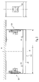
- Fig. 4 is a frontal view of the utility outlined.
- the configuration of the supply device can be such that a head end of a sick bed can be inserted into the niche N , which is laterally formed and bounded by the two vertical elements 2, 6 and above by the transverse connecting element 16.
- the cross-connection element 16 has at least one luminaire.
- the at least one luminaire may in particular comprise a reading light 30 with a predominantly downward or obliquely downward light output and / or a room luminaire 32 with a predominantly horizontal or obliquely upward light output.
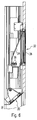
- Fig. 5 is a section along the line B - B off Fig. 4 outlined in which the two mentioned lights 30, 32 can be seen.
- Fig. 6 shows the area around the two lights 30, 32 in more detail.
- the reading light 30 is arranged on the underside of the cross-connecting element 16.
- the bottom can be formed by an oblique covering or cladding element, for example made of aluminum, which has a light exit opening for the reading light 30, in which a preferably plane translucent cover of the reading light 30 - substantially flush with the surrounding cladding element - is arranged.
- the room lamp 32 preferably has a reflector 34 which serves or is designed to direct asymmetrically upwardly or obliquely upward a light generated by a light source 36 of the room light 32.
- the room lamp 32 has a preferably planar-shaped translucent cover 38, which is arranged at least substantially in a plane which is given by a surface of the surrounding cladding element of the cross-connection element 16.
- the supply device can be designed to extend to the ceiling of the relevant room. But it can also be provided that the height is dimensioned such that there is a small distance from the ceiling. In this case, at least one additional illuminant or an additional luminaire can be arranged at the top of the supply device, for example for the generation of an indirect illumination.
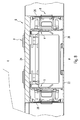
- Fig. 7 is a horizontal section along the line A - A from Fig. 4 shown and in Fig. 8 a detailed view Fig. 7 in the region of the second vertical element 6, however, the sketch applies completely analogously also to the first vertical element 2 or, if appropriate, to each further vertical element 6 '. It can be seen, inter alia, the two - shown here in a variation - supporting elements 20, 22 and the cladding element 24th
- connection element A here for example in the form of a gas connection element; However, it can also generally be a different type of connection element.
- the connection element A is attached to one of the two support elements 20, 22 or to both support elements 20, 22, but not to the cladding element 24. In the example shown, the connection element A is fixed to both support elements 20, 22 by means of anchorages V. By this type of attachment of the connection element A , the risk is reduced that by a manipulation of the connection element A, the cladding element 24 unintentionally detached from the support members 20, 22.
- connection element A on a side surface of a vertical element 2, 6 thus for example at a side facing the niche N side.
- a corresponding connecting element A can for this purpose be fastened to one of the two supporting elements 20, 22 without being fastened to the lining element 24.
- the connection element A -in the example shown in the form of a socket-can preferably be held with respect to the vertical element 2, 6 from the inside, through a hole, for example a milling in the corresponding profile side wall by means of a latching connection. This allows a reliable and easy to make connection.
- a separate guide is preferably provided for low-voltage lines, power lines and gas lines.
- low-voltage lines for example, serve in the vertical element 2, 6 inserted plastic pipes in which the respective lines are guided.
- the first and / or each further vertical element 2, 6, 6 'of the medical supply device has at least one ram protection element 40 for reducing the risk of damaging the vertical element 2, 6, 6'.
- the ram protection element 40 is preferably formed in the region of a front edge of the vertical element 2, 6, 6 ', which forms a boundary of the niche N.
- Fig. 10 For example, a horizontal cross section through a vertical element 2, 6, 6 'outlined.
- the impact protection element 40 is advantageously stably connected directly to one of the support elements 20, 22 shown here again in the variant, for example with special connection elements 42, which are arranged so that they intersect a hole in the respective support element 20, 22.
- a screw connection can be provided for this purpose.
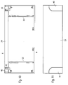
- Fig. 11 is a section of a front view of a vertical element 2, 6, 6 'outlined, which has a ram 40.
- the ram protection element 40 is formed by a separate profile element, for example made of aluminum.
- the cladding elements 24 facing the room side R may be formed by wooden panels and the ram protection element 40 by a metal profile.
- the ram protection element 40 may be designed such that it extends only over part of the height of the vertical element 2, 6, 6 'or over the entire height.
- the Rammtikelement 40 is flush with the surrounding front panel member 24; Accordingly, it is also advantageously designed flush with the adjacent lateral, further cladding element 26.
- a lamp can be particularly advantageous to realize a subtle lighting of the room, for example, as a night or orientation light.
- the vertical element 2, 6, 6 'does not extend all the way to the bottom of the room but, a few centimeters, for example between 5 and 20 cm, is spaced from the floor.
- this luminaire can advantageously have a light emission surface facing down to the ground. A corresponding distance is also advantageous with respect to a cleaning of the floor of the room.
- the front side of a vertical unit 2, 6 need not necessarily be formed by a planar surface, optionally with the corresponding connection elements. It is also possible to provide elements through which, for example, shelves or small cabinets of the like are formed. The design of the surfaces of the panels and the choice of material for this are flexibly selectable. Preferably, it is embodiments that allow easy cleaning.
- the at the transverse modules 16, 16 'provided light exit openings of the at least one lamp or the lights 30, 32 are therefore preferably covered with transparent covers that form a flush surface with the respective surrounding cladding element.
- the supply device according to the invention is generally suitable not only for patient rooms, but can also be suitable, for example, for rooms in nursing homes or hotels.
Landscapes
- Health & Medical Sciences (AREA)
- Nursing (AREA)
- Life Sciences & Earth Sciences (AREA)
- Animal Behavior & Ethology (AREA)
- General Health & Medical Sciences (AREA)
- Public Health (AREA)
- Veterinary Medicine (AREA)
- Accommodation For Nursing Or Treatment Tables (AREA)
Claims (11)
- Dispositif d'alimentation médical pour la mise à disposition de fluides d'alimentation, plus particulièrement de gaz médicaux et de courant, le dispositif d'alimentation étant conçu pour être monté sur un mur avec des lignes d'alimentation des fluides d'alimentation, comprenant :- un premier élément vertical (2) de forme oblongue et conçu pour être monté verticalement, le premier élément vertical (2) comprenant au moins un premier élément de raccordement (4) pour au moins un des fluides d'alimentation,- un deuxième élément vertical (6) de forme oblongue et conçu pour être monté verticalement à une distance horizontale (α) par rapport au premier élément vertical (2), le deuxième élément vertical (6) comprenant au moins un deuxième élément de raccordement (8) pour au moins un des fluides d'alimentation,- au moins une première ligne (10) conduisant un courant, qui reliée de manière conductrice avec l'au moins un premier élément de raccordement (4),- au moins une deuxième ligne (12) conduisant du gaz, qui est reliée de manière conductrice avec l'au moins un deuxième élément de raccordement (8),- une unité d'alimentation et de répartition (14) qui comprend des moyens pour une liaison conductrice entre les lignes d'alimentation d'une part et l'au moins une première ligne (10) et l'au moins une deuxième ligne (12) d'autre part,caractérisé en ce que
l'unité d'alimentation et de répartition (14) fait partie du premier élément vertical (2). - Dispositif d'alimentation médical selon la revendication 1, dans lequel l'unité d'alimentation et de répartition (14) comprend un sous-répartiteur, plus particulièrement un répartiteur de manoeuvre.
- Dispositif d'alimentation médical selon la revendication 1 ou 2, comprenant en outre :- un élément de liaison transversale (16) conçu pour relier une partie supérieure du premier élément vertical (2) avec une partie supérieure du deuxième élément vertical (6).
- Dispositif d'alimentation médical selon la revendication 3, dans lequel l'élément de liaison transversale (16) comprend au moins une lampe (30, 32).
- Dispositif d'alimentation médical selon la revendication 4, dans lequel l'au moins une lampe comprend une lampe de lecture (30) avec une émission de lumière orientée principalement vers le bas ou de manière oblique vers le bas.
- Dispositif d'alimentation médical selon la revendication 4 ou 5, dans lequel l'au moins une lampe comprend une lampe intérieure (32) avec une émission de lumière orientée principalement horizontalement ou de manière oblique vers le haut.
- Dispositif d'alimentation médical selon la revendication 6, dans lequel la lampe intérieure (32) comprend un réflecteur (34) qui permet d'orienter vers le haut ou de manière oblique vers le haut la lumière émise par un moyen d'éclairage (36) de la lampe intérieure (32).
- Dispositif d'alimentation médical selon l'une des revendications précédentes, dans lequel l'élément vertical (2) comprend deux éléments d'appui verticaux (20, 22) ainsi qu'au moins un élément de carénage (24) qui est relié avec un des deux éléments d'appui (20, 22) ou avec les deux éléments d'appui (20, 22) de préférence par l'intermédiaire d'une liaison par encliquetage.
- Dispositif d'alimentation médical selon la revendication 8, dans lequel l'au moins un premier élément de raccordement (4, A) est fixé à un des deux éléments d'appui (20, 22) ou aux deux éléments d'appui (20, 22), mais pas à l'élément de carénage (24).
- Dispositif d'alimentation médical selon l'une des revendications précédentes, comprenant en outre :- au moins un élément antichoc (40) pour la réduction du risque d'un endommagement de premier et/ou du deuxième élément vertical (2, 6, 6'), par exemple du fait d'un lit médicalisé, l'élément antichoc (40) étant constitué de préférence d'un élément profilé séparé.
- Dispositif d'alimentation médical selon l'une des revendications précédentes, comprenant en outre :- une lampe dans une partie inférieure du premier ou du deuxième élément vertical (2, 6, 6') qui est conçue pour émettre de la lumière vers le bas ou en oblique vers le bas.
Applications Claiming Priority (1)
| Application Number | Priority Date | Filing Date | Title |
|---|---|---|---|
| DE201110078874 DE102011078874A1 (de) | 2011-07-08 | 2011-07-08 | Medizinische Versorgungseinrichtung |
Publications (2)
| Publication Number | Publication Date |
|---|---|
| EP2543352A1 EP2543352A1 (fr) | 2013-01-09 |
| EP2543352B1 true EP2543352B1 (fr) | 2016-02-03 |
Family
ID=46420017
Family Applications (1)
| Application Number | Title | Priority Date | Filing Date |
|---|---|---|---|
| EP12175120.0A Not-in-force EP2543352B1 (fr) | 2011-07-08 | 2012-07-05 | Dispositif d'alimentation médical |
Country Status (2)
| Country | Link |
|---|---|
| EP (1) | EP2543352B1 (fr) |
| DE (1) | DE102011078874A1 (fr) |
Families Citing this family (1)
| Publication number | Priority date | Publication date | Assignee | Title |
|---|---|---|---|---|
| US9237979B2 (en) * | 2011-04-11 | 2016-01-19 | Hill-Rom Services, Inc. | Gas distribution assembly |
Family Cites Families (9)
| Publication number | Priority date | Publication date | Assignee | Title |
|---|---|---|---|---|
| US3660591A (en) * | 1970-10-26 | 1972-05-02 | Hill Rom Co Inc | Hospital in-patient service core module |
| DE3106255A1 (de) * | 1981-02-20 | 1982-10-21 | Zumtobel GmbH & Co, 8990 Lindau | Kombinierte anschlusseinrichtung fuer verschiedenartige ver- und entsorgungssysteme |
| US4821470A (en) * | 1988-06-17 | 1989-04-18 | Hill-Rom Company, Inc. | Head wall for hospital bed |
| US4905433A (en) * | 1988-08-29 | 1990-03-06 | Hospital Systems, Inc. | Hospital head wall system |
| DE19514590C1 (de) * | 1995-04-20 | 1996-06-05 | Draegerwerk Ag | Versorgungseinheit |
| DE102004030799A1 (de) * | 2004-06-25 | 2006-01-19 | Zumtobel Staff Gmbh | Versorgungseinrichtung zur Bereitstellung von Versorgungsmedien |
| DE202005016891U1 (de) * | 2005-10-27 | 2007-03-01 | Zumtobel Lighting Gmbh | Versorgungseinrichtung zur Bereitstellung von Versorgungsmedien und Beleuchtungseinheit hierfür |
| US8640391B2 (en) * | 2008-10-16 | 2014-02-04 | Hill-Rom Services, Inc. | Modular architectural room system |
| DE102009020726A1 (de) * | 2009-05-11 | 2010-11-25 | Wesemann Gmbh & Co. Kg | Versorgungssystem zum Bereitstellen einer Medienversorgung |
-
2011
- 2011-07-08 DE DE201110078874 patent/DE102011078874A1/de not_active Withdrawn
-
2012
- 2012-07-05 EP EP12175120.0A patent/EP2543352B1/fr not_active Not-in-force
Also Published As
| Publication number | Publication date |
|---|---|
| EP2543352A1 (fr) | 2013-01-09 |
| DE102011078874A1 (de) | 2013-01-10 |
Similar Documents
| Publication | Publication Date | Title |
|---|---|---|
| EP2220965B1 (fr) | Rails de profil de support et système de présentation | |
| EP2360330B1 (fr) | Connecteur de plinthes | |
| DE2152916A1 (de) | Zentraleinheit | |
| DE102014105855B4 (de) | Schachtbeleuchtungseinrichtung mit bandförmig angeordneten Leuchtdioden, welche gruppenweise parallel geschaltet sind | |
| DE102013104470B4 (de) | Regalsystem mit Beleuchtung | |
| WO2013171148A1 (fr) | Rail de support destiné à fixer et alimenter en électricité plusieurs modules d'éclairage, ainsi que système de bande lumineuse pourvu d'un tel rail de support | |
| EP2093479A1 (fr) | Dispositif de suspension doté d'un rail de support devant être agencé horizontalement | |
| EP2248504B1 (fr) | Unité d'alimentation médicale dotée de modules encastrables | |
| EP0739618B1 (fr) | Unité d'alimentation pour chambres de malade | |
| DE10107912A1 (de) | Einrichtung zum Installieren von Versorgungsleitungen | |
| EP2770127B1 (fr) | Dispositif de montage pour un corps sanitaire | |
| EP2543352A1 (fr) | Dispositif d'alimentation médical | |
| DE10061709A1 (de) | Schrank der elektrischen Hausinstallation | |
| EP1912302A2 (fr) | Dispositif de liaison de postes de travail dans un réseau d'énergie, de données et/ou de communication ainsi que canal de montage et de support pour un tel dispositif | |
| EP2669572B1 (fr) | Unité d'alimentation dotée d'un agencement de lampe | |
| EP3853522B1 (fr) | Système pour montage sur un rail d'énergie suspendu et procédé d'assemblage du système sur un rail électrique | |
| DE20121189U1 (de) | Einrichtung zum Installieren von Versorgungsleitungen | |
| EP1096629A1 (fr) | Unité d'alimentation | |
| EP1612901B1 (fr) | Dispositif d' alimentation pour distribution de produits médicaux. | |
| EP1297810B1 (fr) | Unité d'alimentation médicale | |
| DE1690171C3 (de) | Kombinierte Anschlusseinrichtung fur verschiedenartige Versorgungssysteme | |
| EP0407652A2 (fr) | Mur gainé technique comportant des raccords pour la médecine intensive | |
| EP2262069A2 (fr) | Dispositif pour l'alimentation en liquide et en énergie | |
| DE9411771U1 (de) | Kabelführungseinrichtung | |
| AT525498B1 (de) | Steckbares Beleuchtungssystem für die Pflanzenaufzucht |
Legal Events
| Date | Code | Title | Description |
|---|---|---|---|
| PUAI | Public reference made under article 153(3) epc to a published international application that has entered the european phase |
Free format text: ORIGINAL CODE: 0009012 |
|
| AK | Designated contracting states |
Kind code of ref document: A1 Designated state(s): AL AT BE BG CH CY CZ DE DK EE ES FI FR GB GR HR HU IE IS IT LI LT LU LV MC MK MT NL NO PL PT RO RS SE SI SK SM TR |
|
| AX | Request for extension of the european patent |
Extension state: BA ME |
|
| 17P | Request for examination filed |
Effective date: 20130704 |
|
| RBV | Designated contracting states (corrected) |
Designated state(s): AL AT BE BG CH CY CZ DE DK EE ES FI FR GB GR HR HU IE IS IT LI LT LU LV MC MK MT NL NO PL PT RO RS SE SI SK SM TR |
|
| GRAP | Despatch of communication of intention to grant a patent |
Free format text: ORIGINAL CODE: EPIDOSNIGR1 |
|
| INTG | Intention to grant announced |
Effective date: 20150922 |
|
| GRAS | Grant fee paid |
Free format text: ORIGINAL CODE: EPIDOSNIGR3 |
|
| GRAA | (expected) grant |
Free format text: ORIGINAL CODE: 0009210 |
|
| AK | Designated contracting states |
Kind code of ref document: B1 Designated state(s): AL AT BE BG CH CY CZ DE DK EE ES FI FR GB GR HR HU IE IS IT LI LT LU LV MC MK MT NL NO PL PT RO RS SE SI SK SM TR |
|
| REG | Reference to a national code |
Ref country code: GB Ref legal event code: FG4D Free format text: NOT ENGLISH |
|
| REG | Reference to a national code |
Ref country code: AT Ref legal event code: REF Ref document number: 773315 Country of ref document: AT Kind code of ref document: T Effective date: 20160215 Ref country code: CH Ref legal event code: EP |
|
| REG | Reference to a national code |
Ref country code: IE Ref legal event code: FG4D Free format text: LANGUAGE OF EP DOCUMENT: GERMAN |
|
| REG | Reference to a national code |
Ref country code: DE Ref legal event code: R096 Ref document number: 502012005847 Country of ref document: DE |
|
| REG | Reference to a national code |
Ref country code: CH Ref legal event code: NV Representative=s name: WEINMANN ZIMMERLI, CH |
|
| REG | Reference to a national code |
Ref country code: LT Ref legal event code: MG4D Ref country code: NL Ref legal event code: MP Effective date: 20160203 |
|
| REG | Reference to a national code |
Ref country code: FR Ref legal event code: PLFP Year of fee payment: 5 |
|
| PG25 | Lapsed in a contracting state [announced via postgrant information from national office to epo] |
Ref country code: IT Free format text: LAPSE BECAUSE OF FAILURE TO SUBMIT A TRANSLATION OF THE DESCRIPTION OR TO PAY THE FEE WITHIN THE PRESCRIBED TIME-LIMIT Effective date: 20160203 Ref country code: NO Free format text: LAPSE BECAUSE OF FAILURE TO SUBMIT A TRANSLATION OF THE DESCRIPTION OR TO PAY THE FEE WITHIN THE PRESCRIBED TIME-LIMIT Effective date: 20160503 Ref country code: GR Free format text: LAPSE BECAUSE OF FAILURE TO SUBMIT A TRANSLATION OF THE DESCRIPTION OR TO PAY THE FEE WITHIN THE PRESCRIBED TIME-LIMIT Effective date: 20160504 Ref country code: FI Free format text: LAPSE BECAUSE OF FAILURE TO SUBMIT A TRANSLATION OF THE DESCRIPTION OR TO PAY THE FEE WITHIN THE PRESCRIBED TIME-LIMIT Effective date: 20160203 Ref country code: ES Free format text: LAPSE BECAUSE OF FAILURE TO SUBMIT A TRANSLATION OF THE DESCRIPTION OR TO PAY THE FEE WITHIN THE PRESCRIBED TIME-LIMIT Effective date: 20160203 Ref country code: HR Free format text: LAPSE BECAUSE OF FAILURE TO SUBMIT A TRANSLATION OF THE DESCRIPTION OR TO PAY THE FEE WITHIN THE PRESCRIBED TIME-LIMIT Effective date: 20160203 |
|
| PG25 | Lapsed in a contracting state [announced via postgrant information from national office to epo] |
Ref country code: IS Free format text: LAPSE BECAUSE OF FAILURE TO SUBMIT A TRANSLATION OF THE DESCRIPTION OR TO PAY THE FEE WITHIN THE PRESCRIBED TIME-LIMIT Effective date: 20160603 Ref country code: LT Free format text: LAPSE BECAUSE OF FAILURE TO SUBMIT A TRANSLATION OF THE DESCRIPTION OR TO PAY THE FEE WITHIN THE PRESCRIBED TIME-LIMIT Effective date: 20160203 Ref country code: NL Free format text: LAPSE BECAUSE OF FAILURE TO SUBMIT A TRANSLATION OF THE DESCRIPTION OR TO PAY THE FEE WITHIN THE PRESCRIBED TIME-LIMIT Effective date: 20160203 Ref country code: PL Free format text: LAPSE BECAUSE OF FAILURE TO SUBMIT A TRANSLATION OF THE DESCRIPTION OR TO PAY THE FEE WITHIN THE PRESCRIBED TIME-LIMIT Effective date: 20160203 Ref country code: RS Free format text: LAPSE BECAUSE OF FAILURE TO SUBMIT A TRANSLATION OF THE DESCRIPTION OR TO PAY THE FEE WITHIN THE PRESCRIBED TIME-LIMIT Effective date: 20160203 Ref country code: LV Free format text: LAPSE BECAUSE OF FAILURE TO SUBMIT A TRANSLATION OF THE DESCRIPTION OR TO PAY THE FEE WITHIN THE PRESCRIBED TIME-LIMIT Effective date: 20160203 Ref country code: SE Free format text: LAPSE BECAUSE OF FAILURE TO SUBMIT A TRANSLATION OF THE DESCRIPTION OR TO PAY THE FEE WITHIN THE PRESCRIBED TIME-LIMIT Effective date: 20160203 Ref country code: PT Free format text: LAPSE BECAUSE OF FAILURE TO SUBMIT A TRANSLATION OF THE DESCRIPTION OR TO PAY THE FEE WITHIN THE PRESCRIBED TIME-LIMIT Effective date: 20160603 |
|
| PG25 | Lapsed in a contracting state [announced via postgrant information from national office to epo] |
Ref country code: EE Free format text: LAPSE BECAUSE OF FAILURE TO SUBMIT A TRANSLATION OF THE DESCRIPTION OR TO PAY THE FEE WITHIN THE PRESCRIBED TIME-LIMIT Effective date: 20160203 Ref country code: DK Free format text: LAPSE BECAUSE OF FAILURE TO SUBMIT A TRANSLATION OF THE DESCRIPTION OR TO PAY THE FEE WITHIN THE PRESCRIBED TIME-LIMIT Effective date: 20160203 |
|
| PGFP | Annual fee paid to national office [announced via postgrant information from national office to epo] |
Ref country code: GB Payment date: 20160729 Year of fee payment: 5 Ref country code: CH Payment date: 20160727 Year of fee payment: 5 |
|
| REG | Reference to a national code |
Ref country code: DE Ref legal event code: R097 Ref document number: 502012005847 Country of ref document: DE |
|
| PG25 | Lapsed in a contracting state [announced via postgrant information from national office to epo] |
Ref country code: SK Free format text: LAPSE BECAUSE OF FAILURE TO SUBMIT A TRANSLATION OF THE DESCRIPTION OR TO PAY THE FEE WITHIN THE PRESCRIBED TIME-LIMIT Effective date: 20160203 Ref country code: RO Free format text: LAPSE BECAUSE OF FAILURE TO SUBMIT A TRANSLATION OF THE DESCRIPTION OR TO PAY THE FEE WITHIN THE PRESCRIBED TIME-LIMIT Effective date: 20160203 Ref country code: CZ Free format text: LAPSE BECAUSE OF FAILURE TO SUBMIT A TRANSLATION OF THE DESCRIPTION OR TO PAY THE FEE WITHIN THE PRESCRIBED TIME-LIMIT Effective date: 20160203 Ref country code: SM Free format text: LAPSE BECAUSE OF FAILURE TO SUBMIT A TRANSLATION OF THE DESCRIPTION OR TO PAY THE FEE WITHIN THE PRESCRIBED TIME-LIMIT Effective date: 20160203 |
|
| PGFP | Annual fee paid to national office [announced via postgrant information from national office to epo] |
Ref country code: FR Payment date: 20160728 Year of fee payment: 5 |
|
| PLBE | No opposition filed within time limit |
Free format text: ORIGINAL CODE: 0009261 |
|
| STAA | Information on the status of an ep patent application or granted ep patent |
Free format text: STATUS: NO OPPOSITION FILED WITHIN TIME LIMIT |
|
| PG25 | Lapsed in a contracting state [announced via postgrant information from national office to epo] |
Ref country code: BE Free format text: LAPSE BECAUSE OF NON-PAYMENT OF DUE FEES Effective date: 20160731 |
|
| 26N | No opposition filed |
Effective date: 20161104 |
|
| PGFP | Annual fee paid to national office [announced via postgrant information from national office to epo] |
Ref country code: DE Payment date: 20160930 Year of fee payment: 5 |
|
| PG25 | Lapsed in a contracting state [announced via postgrant information from national office to epo] |
Ref country code: BG Free format text: LAPSE BECAUSE OF FAILURE TO SUBMIT A TRANSLATION OF THE DESCRIPTION OR TO PAY THE FEE WITHIN THE PRESCRIBED TIME-LIMIT Effective date: 20160503 Ref country code: SI Free format text: LAPSE BECAUSE OF FAILURE TO SUBMIT A TRANSLATION OF THE DESCRIPTION OR TO PAY THE FEE WITHIN THE PRESCRIBED TIME-LIMIT Effective date: 20160203 |
|
| PG25 | Lapsed in a contracting state [announced via postgrant information from national office to epo] |
Ref country code: MC Free format text: LAPSE BECAUSE OF FAILURE TO SUBMIT A TRANSLATION OF THE DESCRIPTION OR TO PAY THE FEE WITHIN THE PRESCRIBED TIME-LIMIT Effective date: 20160203 |
|
| REG | Reference to a national code |
Ref country code: IE Ref legal event code: MM4A |
|
| PG25 | Lapsed in a contracting state [announced via postgrant information from national office to epo] |
Ref country code: IE Free format text: LAPSE BECAUSE OF NON-PAYMENT OF DUE FEES Effective date: 20160705 |
|
| PG25 | Lapsed in a contracting state [announced via postgrant information from national office to epo] |
Ref country code: LU Free format text: LAPSE BECAUSE OF NON-PAYMENT OF DUE FEES Effective date: 20160705 |
|
| REG | Reference to a national code |
Ref country code: DE Ref legal event code: R119 Ref document number: 502012005847 Country of ref document: DE |
|
| REG | Reference to a national code |
Ref country code: CH Ref legal event code: PL |
|
| GBPC | Gb: european patent ceased through non-payment of renewal fee |
Effective date: 20170705 |
|
| REG | Reference to a national code |
Ref country code: FR Ref legal event code: ST Effective date: 20180330 |
|
| PG25 | Lapsed in a contracting state [announced via postgrant information from national office to epo] |
Ref country code: DE Free format text: LAPSE BECAUSE OF NON-PAYMENT OF DUE FEES Effective date: 20180201 Ref country code: GB Free format text: LAPSE BECAUSE OF NON-PAYMENT OF DUE FEES Effective date: 20170705 Ref country code: LI Free format text: LAPSE BECAUSE OF NON-PAYMENT OF DUE FEES Effective date: 20170731 Ref country code: CH Free format text: LAPSE BECAUSE OF NON-PAYMENT OF DUE FEES Effective date: 20170731 |
|
| PG25 | Lapsed in a contracting state [announced via postgrant information from national office to epo] |
Ref country code: CY Free format text: LAPSE BECAUSE OF FAILURE TO SUBMIT A TRANSLATION OF THE DESCRIPTION OR TO PAY THE FEE WITHIN THE PRESCRIBED TIME-LIMIT Effective date: 20160203 Ref country code: FR Free format text: LAPSE BECAUSE OF NON-PAYMENT OF DUE FEES Effective date: 20170731 Ref country code: HU Free format text: LAPSE BECAUSE OF FAILURE TO SUBMIT A TRANSLATION OF THE DESCRIPTION OR TO PAY THE FEE WITHIN THE PRESCRIBED TIME-LIMIT; INVALID AB INITIO Effective date: 20120705 |
|
| PG25 | Lapsed in a contracting state [announced via postgrant information from national office to epo] |
Ref country code: MK Free format text: LAPSE BECAUSE OF FAILURE TO SUBMIT A TRANSLATION OF THE DESCRIPTION OR TO PAY THE FEE WITHIN THE PRESCRIBED TIME-LIMIT Effective date: 20160203 Ref country code: TR Free format text: LAPSE BECAUSE OF FAILURE TO SUBMIT A TRANSLATION OF THE DESCRIPTION OR TO PAY THE FEE WITHIN THE PRESCRIBED TIME-LIMIT Effective date: 20160203 Ref country code: MT Free format text: LAPSE BECAUSE OF FAILURE TO SUBMIT A TRANSLATION OF THE DESCRIPTION OR TO PAY THE FEE WITHIN THE PRESCRIBED TIME-LIMIT Effective date: 20160203 |
|
| REG | Reference to a national code |
Ref country code: AT Ref legal event code: MM01 Ref document number: 773315 Country of ref document: AT Kind code of ref document: T Effective date: 20170705 |
|
| PG25 | Lapsed in a contracting state [announced via postgrant information from national office to epo] |
Ref country code: AL Free format text: LAPSE BECAUSE OF FAILURE TO SUBMIT A TRANSLATION OF THE DESCRIPTION OR TO PAY THE FEE WITHIN THE PRESCRIBED TIME-LIMIT Effective date: 20160203 |
|
| PG25 | Lapsed in a contracting state [announced via postgrant information from national office to epo] |
Ref country code: AT Free format text: LAPSE BECAUSE OF NON-PAYMENT OF DUE FEES Effective date: 20170705 |