EP2543490A2 - Unité de fermeture pour une machine de moulage par injection - Google Patents
Unité de fermeture pour une machine de moulage par injection Download PDFInfo
- Publication number
- EP2543490A2 EP2543490A2 EP12185868A EP12185868A EP2543490A2 EP 2543490 A2 EP2543490 A2 EP 2543490A2 EP 12185868 A EP12185868 A EP 12185868A EP 12185868 A EP12185868 A EP 12185868A EP 2543490 A2 EP2543490 A2 EP 2543490A2
- Authority
- EP
- European Patent Office
- Prior art keywords
- columns
- external
- plate
- plates
- middle plate
- Prior art date
- Legal status (The legal status is an assumption and is not a legal conclusion. Google has not performed a legal analysis and makes no representation as to the accuracy of the status listed.)
- Granted
Links
Images


Classifications
-
- B—PERFORMING OPERATIONS; TRANSPORTING
- B29—WORKING OF PLASTICS; WORKING OF SUBSTANCES IN A PLASTIC STATE IN GENERAL
- B29C—SHAPING OR JOINING OF PLASTICS; SHAPING OF MATERIAL IN A PLASTIC STATE, NOT OTHERWISE PROVIDED FOR; AFTER-TREATMENT OF THE SHAPED PRODUCTS, e.g. REPAIRING
- B29C45/00—Injection moulding, i.e. forcing the required volume of moulding material through a nozzle into a closed mould; Apparatus therefor
- B29C45/17—Component parts, details or accessories; Auxiliary operations
- B29C45/64—Mould opening, closing or clamping devices
- B29C45/67—Mould opening, closing or clamping devices hydraulic
-
- B—PERFORMING OPERATIONS; TRANSPORTING
- B29—WORKING OF PLASTICS; WORKING OF SUBSTANCES IN A PLASTIC STATE IN GENERAL
- B29C—SHAPING OR JOINING OF PLASTICS; SHAPING OF MATERIAL IN A PLASTIC STATE, NOT OTHERWISE PROVIDED FOR; AFTER-TREATMENT OF THE SHAPED PRODUCTS, e.g. REPAIRING
- B29C45/00—Injection moulding, i.e. forcing the required volume of moulding material through a nozzle into a closed mould; Apparatus therefor
- B29C45/03—Injection moulding apparatus
- B29C45/12—Injection moulding apparatus using two or more fixed moulds, e.g. in tandem
-
- B—PERFORMING OPERATIONS; TRANSPORTING
- B29—WORKING OF PLASTICS; WORKING OF SUBSTANCES IN A PLASTIC STATE IN GENERAL
- B29C—SHAPING OR JOINING OF PLASTICS; SHAPING OF MATERIAL IN A PLASTIC STATE, NOT OTHERWISE PROVIDED FOR; AFTER-TREATMENT OF THE SHAPED PRODUCTS, e.g. REPAIRING
- B29C45/00—Injection moulding, i.e. forcing the required volume of moulding material through a nozzle into a closed mould; Apparatus therefor
- B29C45/17—Component parts, details or accessories; Auxiliary operations
- B29C45/64—Mould opening, closing or clamping devices
- B29C45/67—Mould opening, closing or clamping devices hydraulic
- B29C45/6707—Mould opening, closing or clamping devices hydraulic without relative movement between the piston and the cylinder of the clamping device during the mould opening or closing movement
- B29C45/6714—Mould opening, closing or clamping devices hydraulic without relative movement between the piston and the cylinder of the clamping device during the mould opening or closing movement using a separate element transmitting the mould clamping force from the clamping cylinder to the mould
- B29C45/6728—Mould opening, closing or clamping devices hydraulic without relative movement between the piston and the cylinder of the clamping device during the mould opening or closing movement using a separate element transmitting the mould clamping force from the clamping cylinder to the mould the separate element consisting of coupling rods
-
- B—PERFORMING OPERATIONS; TRANSPORTING
- B29—WORKING OF PLASTICS; WORKING OF SUBSTANCES IN A PLASTIC STATE IN GENERAL
- B29C—SHAPING OR JOINING OF PLASTICS; SHAPING OF MATERIAL IN A PLASTIC STATE, NOT OTHERWISE PROVIDED FOR; AFTER-TREATMENT OF THE SHAPED PRODUCTS, e.g. REPAIRING
- B29C45/00—Injection moulding, i.e. forcing the required volume of moulding material through a nozzle into a closed mould; Apparatus therefor
- B29C45/17—Component parts, details or accessories; Auxiliary operations
- B29C45/64—Mould opening, closing or clamping devices
- B29C45/67—Mould opening, closing or clamping devices hydraulic
- B29C45/6707—Mould opening, closing or clamping devices hydraulic without relative movement between the piston and the cylinder of the clamping device during the mould opening or closing movement
- B29C2045/6757—Hydraulic locking means
-
- B—PERFORMING OPERATIONS; TRANSPORTING
- B29—WORKING OF PLASTICS; WORKING OF SUBSTANCES IN A PLASTIC STATE IN GENERAL
- B29C—SHAPING OR JOINING OF PLASTICS; SHAPING OF MATERIAL IN A PLASTIC STATE, NOT OTHERWISE PROVIDED FOR; AFTER-TREATMENT OF THE SHAPED PRODUCTS, e.g. REPAIRING
- B29C45/00—Injection moulding, i.e. forcing the required volume of moulding material through a nozzle into a closed mould; Apparatus therefor
- B29C45/03—Injection moulding apparatus
- B29C45/04—Injection moulding apparatus using movable moulds or mould halves
- B29C45/0441—Injection moulding apparatus using movable moulds or mould halves involving a rotational movement
- B29C45/045—Injection moulding apparatus using movable moulds or mould halves involving a rotational movement mounted on the circumference of a rotating support having a rotating axis perpendicular to the mould opening, closing or clamping direction
Definitions
- the invention relates to a closing unit of an injection molding machine with two outer mold platens, with a arranged between the outer mold platens center plate, and with columns for receiving a closing force.
- Locking units with two outer platens and a center plate arranged therebetween are known from the prior art, in which the center plate is designed to be rotatable or else not rotatable in the sense of a classic tier or tandem arrangement. (Johannaber "Kunststoff-millnpens", 4th edition, chapter 5.7.3; DE 10217584 A1 ; WO 2005/035218 A1 ; EP0794045 A1 and EP 1 512 512 A2 ).
- a fixed platen and this opposite a moving platen and a rotatable about a vertical axis center plate can be moved.
- a hydraulic cylinder is provided between this and the fixed platen and the method of the movable platen is done by Eilhubzylinder between the two platens.
- the two platens are connected by four columns, which pass through the mold platens.
- On the movable platen clamps are provided for locking the movable platen with the columns.
- pressure pads are provided on the fixed platen, by means of which the columns can be used together with the movable platen to the fixed platen.
- the middle plate mounted axially immovable on the machine bed and the two outer mold platens are moved to and from this.
- the locking and the closing force structure are carried out in the same way as in the DE 10217584 A1 , ie are on one of the two outer platens Locking systems provided to lock the columns with this mold clamping plate and on the other outer mold clamping plate pressure pads are provided for generating the closing force.
- both aforementioned closing units the molds on both sides of the center plate, ie in both floors, always closed and opened at the same time.
- the double mold opening path of the closing unit is present, since both floors are open at the same time. This requires a relatively large footprint of the injection molding machine, but this must be taken into account in rotating center plates insofar as the rotation of the center plate requires the opening of both floors.
- FIG. 20 From the EP 0794045 A1 , Figures 20 and 21, another clamping unit with a fixed and a movable platen is known, between which a central mold carrier in the machine longitudinal direction movable and is rotatable about a horizontal or a vertical axis. On both sides of the central mold carrier columns are attached, which extend to the two outer mold platens. Those columns that extend to the fixed platen can be retracted and clamped in there arranged clamping devices. Those columns that extend to the movable platen, enforce this and form the piston rods in piston-cylinder units with which the movable platen can be moved to the middle Formenvironlement and away from this and jammed with this.
- the traversing cylinders on the middle mold carrier and the piston-cylinder units on the movable mold clamping plate can be actuated simultaneously to simultaneously close both floors and at the same time carry out an injection process in both floors. But they can also be operated with a small phase shift.
- EP 1 512 512 A2 is another clamping unit in which the middle plate is mounted axially immovable on the machine bed and the two outer mold platens can be moved to this and to this away. In each of the two outer platens four columns are attached, which can be retracted and locked in the center plate.
- the middle plate is rotatable about a vertical axis on a part fixedly connected to the machine bed.
- the middle part can be firmly bolted to the machine bed, ie the middle plate is not rotating, which then corresponds to a so-called tandem injection molding machine.
- Short-stroke hydraulic cylinders or pressure pads for generating a closing force can be provided on each of the two outer platens, for a total of eight short-stroke hydraulic cylinders or pressure pads. In this way, different cycle times can be realized in both floors.
- the present invention seeks to provide a closing unit for an injection molding machine of the type mentioned, in which the two floors or the two working levels can be operated independently of each other in a simple manner.
- the middle plate can be fixedly connected to the machine bed of the injection molding machine and the two outer mold clamping plates slidably supported on the machine bed. If one of the outer mold clamping plates is locked to the center plate and optionally closing pressure is built up, by pressing the linear drive between the two mold mounting plates, the other - not locked - platen relative to the stationary center plate and with respect to this locked platen are moved and vice versa. Due to the pillars fastened to the stationary middle plate, it is possible that alternately one mold clamping plate is always locked to the middle plate and, if appropriate, closing pressure is built up, while the other mold clamping plate can be moved by means of the linear drive.
- one of the outer platen may be fixedly connected to the machine bed and form the fixed platen.
- the other outer platen forms the movable platen and is as well as the middle plate slidably supported on the machine bed.
- the middle plate is locked to the fixed platen and optionally closed pressure is built, by moving the linear drive between the two platen, the movable platen can be moved away from the center plate to open the floor between the center plate and the movable platen. In this case, the columns are not moved.
- one or more hydraulic cylinders can be provided as further linear drives between one of the platens and the center plate in order to move the center plate in a simple manner in a tool installation position can.
- These linear drives are preferably arranged diagonally offset from each other and to the linear drives for the process of the outer mold platens.
- these additional linear drives are not required; in the case of hydraulic cylinders put them on a non-pressurized circuit so that they simply "get along" the traversing movements.
- these further linear drives fastened to the middle plate are to be sometimes referred to as auxiliary drives, in particular in connection with the description of the clamping unit in tandem operation.
- the center plate may include a rotatable mold carrier.
- the center plate may be formed as a support frame and have a plate or cube-shaped mold carrier, which can be rotated by means of a suitable rotary drive to transfer the preforms produced in a floor or working level in the other floor or working level.
- a center plate in this embodiment is known per se, for example from the WO 03/013824 A1 , so that more details on such a center plate are dispensable in the present case.
- two diagonally arranged linear drives can be provided between the two outer mold platens, for example, two diagonally arranged hydraulic cylinder.
- the pillars may be formed as individual pillar pieces attached to both sides of the center plate. But it can also be provided columns which extend through the center plate and are connected to it.
- the injection units are hinged to the two outer platens and are taken in their Verfahrschulen.
- a stationary outer platen and a movable center and a movable outer platen only a movable injection unit is required, which must accommodate the entire closing stroke.
- the closing unit and with it the entire injection molding machine can be designed shorter. Furthermore, there is a reduction due to the shorter mold opening paths the cycle time in tandem operation and thus a gain in production of molded parts. Due to the provided on both outer mold platens pressure pad with locking systems, the injection molding machine, regardless of the respective opposing mold side in each floor generate the maximum closing force. But it can also be generated different closing forces in the two floors.
- the process is usually not offset in time, i. the two floors are opened and closed simultaneously. While approximately in-plane cavities are required in normal floor injection molding machines, this is not necessary due to the locking systems and pressure pad on both platen here.
- the cavities in the two floors can have different surfaces as well as different cooling and plasticizing times. The floor injection molding process can thereby be made more free.
- a hydraulic system which can supply the injection units and the closing unit independently of each other.
- three independent pump units can be provided, one for each of the two injection units and one for the closing unit.
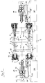
- a fixed platen 2 fixedly mounted on a machine bed 1 and a movable platen 3 and a middle plate 4 on sliding shoes 5 slidably supported.
- a movable platen 3 Between the platen 2 and 3 run four columns 6, of which in the FIG. 1 only to see the front pillars. These columns pass through the center plate 4 and are secured thereto by means of fastening rings 7 on both sides of the center plate.
- a first driving cylinder 8 is fixed to the fixed platen 2, the piston rod 9 is guided past the center plate and hinged to the movable platen 3.
- a same drive cylinder is diagonally offset thereto provided in the region of the rear lower pillar and therefore not visible in the figure.
- an auxiliary cylinder 10 is fixed to the fixed platen 2 in the region of the front lower column, the piston rod 11 is articulated to the middle plate 4.
- An identical auxiliary cylinder is provided diagonally offset at the area of the rear upper column and therefore not visible in the figure.
- the columns 6 pass through the mold platens 2 and 3 and have at their two ends in each case a portion with an annular toothing 12, in which the equipped with a suitable toothing jaws 13 of a hydraulically actuated locking system 14 can engage to the platen on this side of the Pillar with this jam or lock.
- a pressure pad 15 is provided, through which the column 6 is passed hydraulically tight and the pressure chamber 16 via a pressure medium source, not shown here with a pressure medium, such as a hydraulic fluid, can be acted upon by pressure to a closing force produce.
- a locking system and a pressure pad are respectively provided so that the present clamping unit comprises a total of eight locking systems and eight pressure pads.
- the locking systems and pressure pads on the movable platen 3 can be actuated independently of the locking systems and pressure pads on the fixed platen 2.
- injection units 17 and 18 On both sides of the clamping unit are injection units 17 and 18, each with a plasticizing cylinder 19, a plasticizing screw 20, a hydraulic motor 21 for the rotary drive of the screw, a piston-cylinder unit 22 as a linear drive of the screw 20 and a Wegmesssystem 23.
- the rotational movement of the worm 20 may also be provided an electric motor drive.
- displacement cylinders 24 By means of displacement cylinders 24, the injection units can zoom in on the mold platens and be moved away from them.
- the injection unit 18 is mounted on a housing 25 so displaceable that at least the necessary movement for the change of the plasticizing cylinder is possible.
- the housing 25 may be housed a first pump unit for the supply of the hydraulic consumers of the injection unit 18, including the displacement cylinder 24 and a second pump unit for the supply of the closing unit.
- the injection unit 17 is mounted on a frame 28 which is supported by rollers 27 on the housing 26 movable.
- the pump unit for the supply of hydraulic consumers can be accommodated on the side of the movable platen 3, for example for the injection unit 17 and the displacement cylinder 24th
- the center plate 4 with the aid of the auxiliary cylinder 10 and the movable platen with the help of the drive cylinder 8 are moved away from the fixed platen 2, wherein the movable platen 2 is also moved away from the center plate 4, to both sides the middle plate 4 is enough space for the installation of tools.
- the auxiliary cylinders 10 are not needed and therefore switched to pressureless circulation.
- the initial situation for the further explanation of an injection molding cycle should be a state in which the molding tool W2 is closed and the molding tool W1 can be raised in parallel therewith.
- the movable platen 3 is hereby locked with the columns 6 and the pressure chambers 16 on the movable platen 3 are filled with hydraulic fluid under closing pressure, ie the tool 2 is Sch thoroughlybeaufschlagt.
- Now can be injected into the tool W2 produced by the injection unit 17 plastic melt and one or more plastic molded parts are produced, depending on the number of mold cavities in the tool W2. Injection is followed by the repressurization and cooling phases.
- the tool W1 can be ramped up. For this purpose, at the fixed
- the pressure pad 15 relieves pressure and the locking systems 14 moves to its open position in which the locking jaws 13 are moved out of the teeth 12 and are at a distance from the columns.
- the driving cylinder 8 can be actuated, whereby the unit of movable platen 3, tool W2, center plate 4 and the columns 6 is moved away from the fixed platen 2 away.
- the tool W1 is opened and the one or more finished plastic moldings previously produced in the tool W1 can be ejected or removed by means of a robot.
- the tool W1 can be closed again by actuating the drive cylinder 8, wherein the unit of movable platen 3, tool W2, center plate 4 and the columns 6 is moved onto the fixed platen 2.
- the fixed platen 2 can be locked to the columns 6 by their associated locking systems 14 are actuated and after successful locking the pressure pad can be actuated by the pressure chambers 16 are filled at the fixed platen with hydraulic fluid under closing pressure, ie the tool. 1 is locked.
- Now can be injected into the tool W1 produced by the injection unit 18 plastic melt and one or more plastic molded parts are produced, depending on the number of mold cavities in the tool W1. Injection is followed by the repressurization and cooling phases. During this time, the tool W2 can be ascended.
- the pressure pad 15 are relieved of pressure on the movable platen 3 and the locking systems 14 is moved to its open position in which the locking jaws 13 are moved out of the teeth 12 and are at a distance from the columns.
- the driving cylinder 8 can be actuated, whereby the movable platen 3 and clamped on her half of the tool W2 of the unit of center plate 4, columns 6, tool W1 and fixed platen 2 are moved away.
- the tool W2 is opened and the one or more finished plastic moldings produced in the tool W2 can be ejected or removed by means of a robot.
- the tool W2 can be closed by pressing the drive cylinder 8 again.
- both levels are simultaneously or with a desired time shift up and fed in.
- both platens 2 and 3 can be locked with the columns 6 and closing force can be built up.
- Initial situation for the further explanation of this mode of operation should be a state as described in the FIG. 1 is shown, in which both molds W1 and W2 are closed and the cooling phase is completed. First, the pressure pad 15 is relieved at both mold platens 2 and 3 and moves the locking systems 14 in their open position.
- both the displacement cylinder 8 and the auxiliary or Verfahrzylinder 10 are actuated, whereby the center plate 4 and the movable platen 3 are moved away from the fixed platen 2 away.
- both floors or both working levels are ascended by a sufficient distance.
- the finished moldings can be removed and then closed the closing unit again.
- both platen 2 and 3 can be locked again with the columns 6 and re-closing force can be built. If the center plate is equipped with a rotatable mold carrier, a multi-component operation is possible.
- the center plate may be formed as a support frame and have a plate or cube-shaped mold carrier, which is rotated by means of a suitable rotary drive can be in order to transfer the preforms produced in a floor or working level in with the closing unit open in the other floor or working level.
- a support frame is for example in the WO 03/013824 A1 described in various embodiments and can therefore be assumed to be known in the present case.
- FIG. 2 shows an alternative embodiment, in which the middle plate 4 is fixedly connected to the machine bed 1 and the two outer mold platens are designed as movable mold mounting plates 3a and 3b and slidably supported on slide shoes 5 on the machine bed 1. Furthermore, now both injection units 17 and 18 are slidably supported on rollers 27 so that they can be moved in the process of the outer platen 3a, 3b. Otherwise, this embodiment corresponds to that of FIG. 1 ,
- the installation of the tools W1 and W2 is carried out analogously as in the first embodiment according to FIG. 1 in which the right movable platen 3b is moved away from the middle plate 4 by means of the auxiliary cylinders 10 and the left movable platen 3a is moved away from the right movable platen 3b and the middle plate 4 by means of the driving cylinders 8. Before the driving cylinders 8 are operated, it may be necessary to lock the right movable platen 3b to the columns 6.
- the operation of the injection molding according to FIG. 2 is substantially the same in both tandem operation and in multi-component or multi-component operation as in the embodiment according to FIG. 1 with the difference that the center plate 4 and the columns 6 are never moved, but the outer mold platens 3a and 3b will move away from or towards the center plate, in tandem operation alternately and in multi-component and multi-component operation simultaneously or with a desired phase shift.
- the respective traversing movements are carried out by actuation of the driving cylinder 8, when the one platen is locked with the columns and thus with the middle plate - and optionally the pressure chamber is pressurized closing - and the other platen is unlocked and can be moved away from the center plate ,
- the locking systems 14 and the pressure pads 15 are as in the above operated first embodiment described alternately. While on the side of the left movable platen 3a, the locking systems are locked and the pressure pad is pressurized, on the right movable platen 3b side, after opening the tool W1, the pressure pads can be relieved of pressure and the locking systems unlocked, and vice versa.
- the traversing movements are carried out by actuation of the drive cylinder 8 and the auxiliary or traversing cylinder 10 when both form platens are unlocked.
- both platens 2 and 3 are moved away from the middle plate 4 by a sufficient distance and thus both floors or working planes are driven up far enough.
- the production process in tandem operation based on the fact that the manufacturing process for the plastic molded parts in the two floors with the tools W1 and W2 is performed offset in time with each other. While the functions “Injection”, “Hold”, “Cool” and “Plastify” run on one side of the tool, the functions of the "Open”, if necessary “Core Pulling”, “Ejecting” and “Closing” functions expire on the side of the other tool ,
- the invention all applications can be carried out in the field of a classic tandem injection molding machine.
- the same or different moldings can be made.
- mirror-inverted molded parts such as a right and a left interior trim of a vehicle door in the two floors can be made.
- the invention is also particularly suitable for the production of large-volume parts with a long cooling time such as pallets.
- the closing unit according to the invention is therefore universally usable.
- FIG. 3 shows a further embodiment with a fixed center plate 4 and two outer movable mold mounting plates 3a and 3b, in which the functions and closing force structure are integrated into one and the same piston-cylinder units.
- four piston-cylinder units 29 are provided, each having an inner part as Verfahrzylinder 29a and an outer part as the actual lock cylinder 29b.
- the operation of the injection molding according to FIG. 3 is substantially the same as above in the embodiment according to the FIG. 2 described, both in tandem operation and in multi-level or multi-component operation.
- the respective movements are carried out by operating the Verfahrzylinder 29a on the mold platen to be traversed when the non-traversing platen is locked to the center plate - for example, by hydraulic blockage of the piston-cylinder units 29 to this stationary platen.
- the piston-cylinder units 29 are analogous to the embodiment according to the FIG. 2 operated alternately. While on the side of the left movable platen 3a, the local piston-cylinder units 29 are acted upon by closing force, ie the local lock cylinder 29b, on the side of the right movable platen 3b, the shooting cylinder 29b relieved of pressure on this side and actuates the associated Verfahrzylinder 29 be - and vice versa. On the other hand, in multi-component and multi-level operation, the piston-cylinder units are usually actuated simultaneously.
Landscapes
- Engineering & Computer Science (AREA)
- Manufacturing & Machinery (AREA)
- Mechanical Engineering (AREA)
- Moulds For Moulding Plastics Or The Like (AREA)
- Injection Moulding Of Plastics Or The Like (AREA)
Applications Claiming Priority (3)
| Application Number | Priority Date | Filing Date | Title |
|---|---|---|---|
| DE102006026846A DE102006026846A1 (de) | 2006-06-09 | 2006-06-09 | Schließeinheit für eine Tandem-Spritzgießmaschine |
| PCT/EP2007/055438 WO2007141228A1 (fr) | 2006-06-09 | 2007-06-04 | Dispositif de fermeture pour presse d'injection |
| EP07729826.3A EP2032327B1 (fr) | 2006-06-09 | 2007-06-04 | Dispositif de fermeture pour presse d'injection |
Related Parent Applications (2)
| Application Number | Title | Priority Date | Filing Date |
|---|---|---|---|
| EP07729826.3 Division | 2007-06-04 | ||
| EP07729826.3A Division EP2032327B1 (fr) | 2006-06-09 | 2007-06-04 | Dispositif de fermeture pour presse d'injection |
Publications (3)
| Publication Number | Publication Date |
|---|---|
| EP2543490A2 true EP2543490A2 (fr) | 2013-01-09 |
| EP2543490A3 EP2543490A3 (fr) | 2017-07-19 |
| EP2543490B1 EP2543490B1 (fr) | 2018-08-29 |
Family
ID=38266712
Family Applications (2)
| Application Number | Title | Priority Date | Filing Date |
|---|---|---|---|
| EP07729826.3A Not-in-force EP2032327B1 (fr) | 2006-06-09 | 2007-06-04 | Dispositif de fermeture pour presse d'injection |
| EP12185868.2A Not-in-force EP2543490B1 (fr) | 2006-06-09 | 2007-06-04 | Unité de fermeture pour une machine de moulage par injection |
Family Applications Before (1)
| Application Number | Title | Priority Date | Filing Date |
|---|---|---|---|
| EP07729826.3A Not-in-force EP2032327B1 (fr) | 2006-06-09 | 2007-06-04 | Dispositif de fermeture pour presse d'injection |
Country Status (3)
| Country | Link |
|---|---|
| EP (2) | EP2032327B1 (fr) |
| DE (1) | DE102006026846A1 (fr) |
| WO (1) | WO2007141228A1 (fr) |
Families Citing this family (4)
| Publication number | Priority date | Publication date | Assignee | Title |
|---|---|---|---|---|
| CN109591257A (zh) * | 2017-02-07 | 2019-04-09 | 合肥智慧龙图腾知识产权股份有限公司 | 一种批量塑料勺的立式插入注塑成型模结构 |
| CN107225662A (zh) * | 2017-06-30 | 2017-10-03 | 浙江开元新型墙体材料有限公司 | 自带字体标签的蒸压加气板材生产设备 |
| CN114474506B (zh) * | 2022-02-24 | 2023-06-20 | 扬州钰能精密机械科技有限公司 | 一种具有锁紧功能的高精度粉末注射模具 |
| CN115071082B (zh) * | 2022-04-29 | 2023-09-19 | 宁波长飞亚塑料机械制造有限公司 | 一种实现对射注塑机的微开模系统及其控制方法 |
Citations (5)
| Publication number | Priority date | Publication date | Assignee | Title |
|---|---|---|---|---|
| EP0794045A1 (fr) | 1996-03-06 | 1997-09-10 | Husky Injection Molding Systems Ltd. | Machine à tourelle pour mouler des articles |
| DE10217584A1 (de) | 2001-05-08 | 2002-11-14 | Engel Gmbh Maschbau | Spritzgießeinrichtung |
| WO2003013824A1 (fr) | 2001-08-03 | 2003-02-20 | Krauss-Maffei Kunststofftechnik Gmbh | Dispositif de serrage de moule conçu pour une presse a injection |
| EP1512512A2 (fr) | 2003-08-14 | 2005-03-09 | Battenfeld GmbH | Appareil de moulage par injection |
| WO2005035218A1 (fr) | 2003-10-09 | 2005-04-21 | Krauss-Maffei Kunststofftechnik Gmbh | Machine de moulage par injection horizontale pourvue d'un dispositif tournant |
Family Cites Families (7)
| Publication number | Priority date | Publication date | Assignee | Title |
|---|---|---|---|---|
| US3880560A (en) * | 1973-06-19 | 1975-04-29 | Takahashi Seiki Co Ltd | Molding machine for synthetic resin article |
| JPS5644635A (en) | 1979-09-19 | 1981-04-23 | Japan Steel Works Ltd:The | Mold-clamping device for injection molder |
| DE3611723A1 (de) * | 1986-04-08 | 1987-10-15 | Stuebbe Gmbh Maschf | Spritzgiessmaschine zum herstellen von kunststoffteilen im spritzgiess- oder reaktionsspritzgiessverfahren |
| DE4336572C1 (de) * | 1993-10-27 | 1994-12-15 | Ferromatik Milacron Maschinenb | Formzuhaltevorrichtung, insbesondere an Spritzgießmaschinen |
| JP2696061B2 (ja) * | 1993-12-29 | 1998-01-14 | 株式会社神戸製鋼所 | 2層発泡射出成形装置 |
| US5645875A (en) * | 1995-06-07 | 1997-07-08 | Husky Injection Molding Systems Ltd. | Securing/clamping assembly for injection molding machines |
| AT8048U1 (de) * | 2004-10-13 | 2006-01-15 | Engel Austria Gmbh | Verfahren zum betrieb einer spritzgiessmaschine |
-
2006
- 2006-06-09 DE DE102006026846A patent/DE102006026846A1/de not_active Withdrawn
-
2007
- 2007-06-04 EP EP07729826.3A patent/EP2032327B1/fr not_active Not-in-force
- 2007-06-04 EP EP12185868.2A patent/EP2543490B1/fr not_active Not-in-force
- 2007-06-04 WO PCT/EP2007/055438 patent/WO2007141228A1/fr not_active Ceased
Patent Citations (5)
| Publication number | Priority date | Publication date | Assignee | Title |
|---|---|---|---|---|
| EP0794045A1 (fr) | 1996-03-06 | 1997-09-10 | Husky Injection Molding Systems Ltd. | Machine à tourelle pour mouler des articles |
| DE10217584A1 (de) | 2001-05-08 | 2002-11-14 | Engel Gmbh Maschbau | Spritzgießeinrichtung |
| WO2003013824A1 (fr) | 2001-08-03 | 2003-02-20 | Krauss-Maffei Kunststofftechnik Gmbh | Dispositif de serrage de moule conçu pour une presse a injection |
| EP1512512A2 (fr) | 2003-08-14 | 2005-03-09 | Battenfeld GmbH | Appareil de moulage par injection |
| WO2005035218A1 (fr) | 2003-10-09 | 2005-04-21 | Krauss-Maffei Kunststofftechnik Gmbh | Machine de moulage par injection horizontale pourvue d'un dispositif tournant |
Also Published As
| Publication number | Publication date |
|---|---|
| WO2007141228A1 (fr) | 2007-12-13 |
| DE102006026846A1 (de) | 2007-12-13 |
| EP2543490B1 (fr) | 2018-08-29 |
| EP2543490A3 (fr) | 2017-07-19 |
| EP2032327B1 (fr) | 2013-11-06 |
| EP2032327A1 (fr) | 2009-03-11 |
Similar Documents
| Publication | Publication Date | Title |
|---|---|---|
| DE3448497C2 (de) | Blasformmaschine | |
| EP1673208A1 (fr) | Machine de moulage par injection horizontale pourvue d'un dispositif tournant | |
| EP2266783A2 (fr) | Dispositif de serrage de moule pour une presse à injecter | |
| DE102004057164A1 (de) | Spritzgießmaschine | |
| EP3710222B1 (fr) | Unité de fermeture de moule destinée à une machine de moulage par injection ainsi que procédé de blocage d'un élément de transmission de force | |
| EP2543490B1 (fr) | Unité de fermeture pour une machine de moulage par injection | |
| EP0576837B1 (fr) | Machine à mouler par injection avec moule à étages | |
| EP3672776B1 (fr) | Unité de fermeture de moule destinée à une machine de moulage par injection ainsi que procédé de blocage d'un élément de transmission de force | |
| AT509907B1 (de) | Schliesseinheit für eine spritzgiessmaschine | |
| EP1802441B1 (fr) | Unite de fermeture destinee a une machine de moulage par injection comportant un moule a etages | |
| EP4458547A1 (fr) | Unité de fermeture de moule et procédé de fonctionnement d'une unité de fermeture de moule d'une machine de traitement de matières plastiques | |
| EP1858682B1 (fr) | Dispositif pour recevoir un moule de soufflage | |
| EP1647393A2 (fr) | Dispositif de serrage de moule pour une presse à injecter | |
| DE2235758C3 (de) | Formschließvorrichtung einer Kunststoff-Spritzgießmaschine | |
| DE102006026608B4 (de) | Säulenziehvorrichtung | |
| DE102024136234B3 (de) | Formschließeinheit | |
| EP3718732A1 (fr) | Procédé et dispositif de fabrication des pièces moulées en matière plastique à plusieurs composants | |
| DE4340258C2 (de) | Spritzgießmaschine mit Etagenwerkzeug | |
| DE102009020376B3 (de) | Spritzgießmaschine und Verfahren zum Betreiben einer solchen | |
| DE102011011264B3 (de) | Formschließvorrichtung | |
| EP0289857B1 (fr) | Unité de fermeture pour machines à mouler par injection | |
| WO2014013003A1 (fr) | Unité de fermeture pour une machine de moulage par injection de matière plastique |
Legal Events
| Date | Code | Title | Description |
|---|---|---|---|
| PUAI | Public reference made under article 153(3) epc to a published international application that has entered the european phase |
Free format text: ORIGINAL CODE: 0009012 |
|
| AC | Divisional application: reference to earlier application |
Ref document number: 2032327 Country of ref document: EP Kind code of ref document: P |
|
| AK | Designated contracting states |
Kind code of ref document: A2 Designated state(s): AT BE BG CH CY CZ DE DK EE ES FI FR GB GR HU IE IS IT LI LT LU LV MC MT NL PL PT RO SE SI SK TR |
|
| RAP1 | Party data changed (applicant data changed or rights of an application transferred) |
Owner name: KRAUSSMAFFEI TECHNOLOGIES GMBH |
|
| PUAL | Search report despatched |
Free format text: ORIGINAL CODE: 0009013 |
|
| AK | Designated contracting states |
Kind code of ref document: A3 Designated state(s): AT BE BG CH CY CZ DE DK EE ES FI FR GB GR HU IE IS IT LI LT LU LV MC MT NL PL PT RO SE SI SK TR |
|
| RIC1 | Information provided on ipc code assigned before grant |
Ipc: B29C 45/12 20060101AFI20170609BHEP Ipc: B29C 45/67 20060101ALI20170609BHEP Ipc: B29C 45/04 20060101ALN20170609BHEP |
|
| STAA | Information on the status of an ep patent application or granted ep patent |
Free format text: STATUS: REQUEST FOR EXAMINATION WAS MADE |
|
| 17P | Request for examination filed |
Effective date: 20171114 |
|
| RBV | Designated contracting states (corrected) |
Designated state(s): AT BE BG CH CY CZ DE DK EE ES FI FR GB GR HU IE IS IT LI LT LU LV MC MT NL PL PT RO SE SI SK TR |
|
| GRAP | Despatch of communication of intention to grant a patent |
Free format text: ORIGINAL CODE: EPIDOSNIGR1 |
|
| STAA | Information on the status of an ep patent application or granted ep patent |
Free format text: STATUS: GRANT OF PATENT IS INTENDED |
|
| RIC1 | Information provided on ipc code assigned before grant |
Ipc: B29C 45/67 20060101ALI20180309BHEP Ipc: B29C 45/12 20060101AFI20180309BHEP Ipc: B29C 45/04 20060101ALN20180309BHEP |
|
| INTG | Intention to grant announced |
Effective date: 20180329 |
|
| GRAS | Grant fee paid |
Free format text: ORIGINAL CODE: EPIDOSNIGR3 |
|
| GRAA | (expected) grant |
Free format text: ORIGINAL CODE: 0009210 |
|
| STAA | Information on the status of an ep patent application or granted ep patent |
Free format text: STATUS: THE PATENT HAS BEEN GRANTED |
|
| AC | Divisional application: reference to earlier application |
Ref document number: 2032327 Country of ref document: EP Kind code of ref document: P |
|
| AK | Designated contracting states |
Kind code of ref document: B1 Designated state(s): AT BE BG CH CY CZ DE DK EE ES FI FR GB GR HU IE IS IT LI LT LU LV MC MT NL PL PT RO SE SI SK TR |
|
| REG | Reference to a national code |
Ref country code: GB Ref legal event code: FG4D Free format text: NOT ENGLISH |
|
| REG | Reference to a national code |
Ref country code: CH Ref legal event code: EP |
|
| REG | Reference to a national code |
Ref country code: AT Ref legal event code: REF Ref document number: 1034612 Country of ref document: AT Kind code of ref document: T Effective date: 20180915 |
|
| REG | Reference to a national code |
Ref country code: IE Ref legal event code: FG4D Free format text: LANGUAGE OF EP DOCUMENT: GERMAN |
|
| REG | Reference to a national code |
Ref country code: DE Ref legal event code: R096 Ref document number: 502007016364 Country of ref document: DE |
|
| REG | Reference to a national code |
Ref country code: NL Ref legal event code: MP Effective date: 20180829 |
|
| REG | Reference to a national code |
Ref country code: LT Ref legal event code: MG4D |
|
| PG25 | Lapsed in a contracting state [announced via postgrant information from national office to epo] |
Ref country code: FI Free format text: LAPSE BECAUSE OF FAILURE TO SUBMIT A TRANSLATION OF THE DESCRIPTION OR TO PAY THE FEE WITHIN THE PRESCRIBED TIME-LIMIT Effective date: 20180829 Ref country code: IS Free format text: LAPSE BECAUSE OF FAILURE TO SUBMIT A TRANSLATION OF THE DESCRIPTION OR TO PAY THE FEE WITHIN THE PRESCRIBED TIME-LIMIT Effective date: 20181229 Ref country code: LT Free format text: LAPSE BECAUSE OF FAILURE TO SUBMIT A TRANSLATION OF THE DESCRIPTION OR TO PAY THE FEE WITHIN THE PRESCRIBED TIME-LIMIT Effective date: 20180829 Ref country code: BG Free format text: LAPSE BECAUSE OF FAILURE TO SUBMIT A TRANSLATION OF THE DESCRIPTION OR TO PAY THE FEE WITHIN THE PRESCRIBED TIME-LIMIT Effective date: 20181129 Ref country code: SE Free format text: LAPSE BECAUSE OF FAILURE TO SUBMIT A TRANSLATION OF THE DESCRIPTION OR TO PAY THE FEE WITHIN THE PRESCRIBED TIME-LIMIT Effective date: 20180829 Ref country code: NL Free format text: LAPSE BECAUSE OF FAILURE TO SUBMIT A TRANSLATION OF THE DESCRIPTION OR TO PAY THE FEE WITHIN THE PRESCRIBED TIME-LIMIT Effective date: 20180829 Ref country code: GR Free format text: LAPSE BECAUSE OF FAILURE TO SUBMIT A TRANSLATION OF THE DESCRIPTION OR TO PAY THE FEE WITHIN THE PRESCRIBED TIME-LIMIT Effective date: 20181130 |
|
| PG25 | Lapsed in a contracting state [announced via postgrant information from national office to epo] |
Ref country code: LV Free format text: LAPSE BECAUSE OF FAILURE TO SUBMIT A TRANSLATION OF THE DESCRIPTION OR TO PAY THE FEE WITHIN THE PRESCRIBED TIME-LIMIT Effective date: 20180829 |
|
| PG25 | Lapsed in a contracting state [announced via postgrant information from national office to epo] |
Ref country code: ES Free format text: LAPSE BECAUSE OF FAILURE TO SUBMIT A TRANSLATION OF THE DESCRIPTION OR TO PAY THE FEE WITHIN THE PRESCRIBED TIME-LIMIT Effective date: 20180829 Ref country code: PL Free format text: LAPSE BECAUSE OF FAILURE TO SUBMIT A TRANSLATION OF THE DESCRIPTION OR TO PAY THE FEE WITHIN THE PRESCRIBED TIME-LIMIT Effective date: 20180829 Ref country code: RO Free format text: LAPSE BECAUSE OF FAILURE TO SUBMIT A TRANSLATION OF THE DESCRIPTION OR TO PAY THE FEE WITHIN THE PRESCRIBED TIME-LIMIT Effective date: 20180829 Ref country code: EE Free format text: LAPSE BECAUSE OF FAILURE TO SUBMIT A TRANSLATION OF THE DESCRIPTION OR TO PAY THE FEE WITHIN THE PRESCRIBED TIME-LIMIT Effective date: 20180829 |
|
| PG25 | Lapsed in a contracting state [announced via postgrant information from national office to epo] |
Ref country code: DK Free format text: LAPSE BECAUSE OF FAILURE TO SUBMIT A TRANSLATION OF THE DESCRIPTION OR TO PAY THE FEE WITHIN THE PRESCRIBED TIME-LIMIT Effective date: 20180829 Ref country code: SK Free format text: LAPSE BECAUSE OF FAILURE TO SUBMIT A TRANSLATION OF THE DESCRIPTION OR TO PAY THE FEE WITHIN THE PRESCRIBED TIME-LIMIT Effective date: 20180829 |
|
| REG | Reference to a national code |
Ref country code: DE Ref legal event code: R097 Ref document number: 502007016364 Country of ref document: DE |
|
| PLBE | No opposition filed within time limit |
Free format text: ORIGINAL CODE: 0009261 |
|
| STAA | Information on the status of an ep patent application or granted ep patent |
Free format text: STATUS: NO OPPOSITION FILED WITHIN TIME LIMIT |
|
| PGFP | Annual fee paid to national office [announced via postgrant information from national office to epo] |
Ref country code: CZ Payment date: 20190531 Year of fee payment: 13 |
|
| 26N | No opposition filed |
Effective date: 20190531 |
|
| PG25 | Lapsed in a contracting state [announced via postgrant information from national office to epo] |
Ref country code: SI Free format text: LAPSE BECAUSE OF FAILURE TO SUBMIT A TRANSLATION OF THE DESCRIPTION OR TO PAY THE FEE WITHIN THE PRESCRIBED TIME-LIMIT Effective date: 20180829 |
|
| PG25 | Lapsed in a contracting state [announced via postgrant information from national office to epo] |
Ref country code: MC Free format text: LAPSE BECAUSE OF FAILURE TO SUBMIT A TRANSLATION OF THE DESCRIPTION OR TO PAY THE FEE WITHIN THE PRESCRIBED TIME-LIMIT Effective date: 20180829 |
|
| REG | Reference to a national code |
Ref country code: CH Ref legal event code: PL |
|
| GBPC | Gb: european patent ceased through non-payment of renewal fee |
Effective date: 20190604 |
|
| REG | Reference to a national code |
Ref country code: BE Ref legal event code: MM Effective date: 20190630 |
|
| PG25 | Lapsed in a contracting state [announced via postgrant information from national office to epo] |
Ref country code: TR Free format text: LAPSE BECAUSE OF FAILURE TO SUBMIT A TRANSLATION OF THE DESCRIPTION OR TO PAY THE FEE WITHIN THE PRESCRIBED TIME-LIMIT Effective date: 20180829 |
|
| PG25 | Lapsed in a contracting state [announced via postgrant information from national office to epo] |
Ref country code: IT Free format text: LAPSE BECAUSE OF NON-PAYMENT OF DUE FEES Effective date: 20190604 Ref country code: IE Free format text: LAPSE BECAUSE OF NON-PAYMENT OF DUE FEES Effective date: 20190604 Ref country code: GB Free format text: LAPSE BECAUSE OF NON-PAYMENT OF DUE FEES Effective date: 20190604 |
|
| PG25 | Lapsed in a contracting state [announced via postgrant information from national office to epo] |
Ref country code: CH Free format text: LAPSE BECAUSE OF NON-PAYMENT OF DUE FEES Effective date: 20190630 Ref country code: LU Free format text: LAPSE BECAUSE OF NON-PAYMENT OF DUE FEES Effective date: 20190604 Ref country code: LI Free format text: LAPSE BECAUSE OF NON-PAYMENT OF DUE FEES Effective date: 20190630 Ref country code: BE Free format text: LAPSE BECAUSE OF NON-PAYMENT OF DUE FEES Effective date: 20190630 |
|
| PG25 | Lapsed in a contracting state [announced via postgrant information from national office to epo] |
Ref country code: PT Free format text: LAPSE BECAUSE OF FAILURE TO SUBMIT A TRANSLATION OF THE DESCRIPTION OR TO PAY THE FEE WITHIN THE PRESCRIBED TIME-LIMIT Effective date: 20181229 Ref country code: FR Free format text: LAPSE BECAUSE OF NON-PAYMENT OF DUE FEES Effective date: 20190630 |
|
| PG25 | Lapsed in a contracting state [announced via postgrant information from national office to epo] |
Ref country code: CZ Free format text: LAPSE BECAUSE OF NON-PAYMENT OF DUE FEES Effective date: 20200604 |
|
| PG25 | Lapsed in a contracting state [announced via postgrant information from national office to epo] |
Ref country code: CY Free format text: LAPSE BECAUSE OF FAILURE TO SUBMIT A TRANSLATION OF THE DESCRIPTION OR TO PAY THE FEE WITHIN THE PRESCRIBED TIME-LIMIT Effective date: 20180829 |
|
| PG25 | Lapsed in a contracting state [announced via postgrant information from national office to epo] |
Ref country code: HU Free format text: LAPSE BECAUSE OF FAILURE TO SUBMIT A TRANSLATION OF THE DESCRIPTION OR TO PAY THE FEE WITHIN THE PRESCRIBED TIME-LIMIT; INVALID AB INITIO Effective date: 20070604 Ref country code: MT Free format text: LAPSE BECAUSE OF FAILURE TO SUBMIT A TRANSLATION OF THE DESCRIPTION OR TO PAY THE FEE WITHIN THE PRESCRIBED TIME-LIMIT Effective date: 20180829 |
|
| PGFP | Annual fee paid to national office [announced via postgrant information from national office to epo] |
Ref country code: DE Payment date: 20220620 Year of fee payment: 16 |
|
| PGFP | Annual fee paid to national office [announced via postgrant information from national office to epo] |
Ref country code: AT Payment date: 20220621 Year of fee payment: 16 |
|
| REG | Reference to a national code |
Ref country code: DE Ref legal event code: R119 Ref document number: 502007016364 Country of ref document: DE |
|
| REG | Reference to a national code |
Ref country code: AT Ref legal event code: MM01 Ref document number: 1034612 Country of ref document: AT Kind code of ref document: T Effective date: 20230604 |
|
| PG25 | Lapsed in a contracting state [announced via postgrant information from national office to epo] |
Ref country code: AT Free format text: LAPSE BECAUSE OF NON-PAYMENT OF DUE FEES Effective date: 20230604 |
|
| PG25 | Lapsed in a contracting state [announced via postgrant information from national office to epo] |
Ref country code: DE Free format text: LAPSE BECAUSE OF NON-PAYMENT OF DUE FEES Effective date: 20240103 Ref country code: AT Free format text: LAPSE BECAUSE OF NON-PAYMENT OF DUE FEES Effective date: 20230604 |