EP3718732A1 - Procédé et dispositif de fabrication des pièces moulées en matière plastique à plusieurs composants - Google Patents
Procédé et dispositif de fabrication des pièces moulées en matière plastique à plusieurs composants Download PDFInfo
- Publication number
- EP3718732A1 EP3718732A1 EP20167277.1A EP20167277A EP3718732A1 EP 3718732 A1 EP3718732 A1 EP 3718732A1 EP 20167277 A EP20167277 A EP 20167277A EP 3718732 A1 EP3718732 A1 EP 3718732A1
- Authority
- EP
- European Patent Office
- Prior art keywords
- tool
- rim
- injection molding
- movable
- halves
- Prior art date
- Legal status (The legal status is an assumption and is not a legal conclusion. Google has not performed a legal analysis and makes no representation as to the accuracy of the status listed.)
- Granted
Links
Images



Classifications
-
- B—PERFORMING OPERATIONS; TRANSPORTING
- B29—WORKING OF PLASTICS; WORKING OF SUBSTANCES IN A PLASTIC STATE IN GENERAL
- B29C—SHAPING OR JOINING OF PLASTICS; SHAPING OF MATERIAL IN A PLASTIC STATE, NOT OTHERWISE PROVIDED FOR; AFTER-TREATMENT OF THE SHAPED PRODUCTS, e.g. REPAIRING
- B29C45/00—Injection moulding, i.e. forcing the required volume of moulding material through a nozzle into a closed mould; Apparatus therefor
- B29C45/16—Making multilayered or multicoloured articles
- B29C45/1679—Making multilayered or multicoloured articles applying surface layers onto injection-moulded substrates inside the mould cavity, e.g. in-mould coating [IMC]
-
- B—PERFORMING OPERATIONS; TRANSPORTING
- B29—WORKING OF PLASTICS; WORKING OF SUBSTANCES IN A PLASTIC STATE IN GENERAL
- B29C—SHAPING OR JOINING OF PLASTICS; SHAPING OF MATERIAL IN A PLASTIC STATE, NOT OTHERWISE PROVIDED FOR; AFTER-TREATMENT OF THE SHAPED PRODUCTS, e.g. REPAIRING
- B29C45/00—Injection moulding, i.e. forcing the required volume of moulding material through a nozzle into a closed mould; Apparatus therefor
- B29C45/16—Making multilayered or multicoloured articles
- B29C45/1615—The materials being injected at different moulding stations
-
- B—PERFORMING OPERATIONS; TRANSPORTING
- B29—WORKING OF PLASTICS; WORKING OF SUBSTANCES IN A PLASTIC STATE IN GENERAL
- B29C—SHAPING OR JOINING OF PLASTICS; SHAPING OF MATERIAL IN A PLASTIC STATE, NOT OTHERWISE PROVIDED FOR; AFTER-TREATMENT OF THE SHAPED PRODUCTS, e.g. REPAIRING
- B29C45/00—Injection moulding, i.e. forcing the required volume of moulding material through a nozzle into a closed mould; Apparatus therefor
- B29C45/16—Making multilayered or multicoloured articles
- B29C45/1615—The materials being injected at different moulding stations
- B29C45/162—The materials being injected at different moulding stations using means, e.g. mould parts, for transferring an injected part between moulding stations
-
- B—PERFORMING OPERATIONS; TRANSPORTING
- B29—WORKING OF PLASTICS; WORKING OF SUBSTANCES IN A PLASTIC STATE IN GENERAL
- B29C—SHAPING OR JOINING OF PLASTICS; SHAPING OF MATERIAL IN A PLASTIC STATE, NOT OTHERWISE PROVIDED FOR; AFTER-TREATMENT OF THE SHAPED PRODUCTS, e.g. REPAIRING
- B29C67/00—Shaping techniques not covered by groups B29C39/00 - B29C65/00, B29C70/00 or B29C73/00
- B29C67/24—Shaping techniques not covered by groups B29C39/00 - B29C65/00, B29C70/00 or B29C73/00 characterised by the choice of material
- B29C67/246—Moulding high reactive monomers or prepolymers, e.g. by reaction injection moulding [RIM], liquid injection moulding [LIM]
-
- B—PERFORMING OPERATIONS; TRANSPORTING
- B29—WORKING OF PLASTICS; WORKING OF SUBSTANCES IN A PLASTIC STATE IN GENERAL
- B29C—SHAPING OR JOINING OF PLASTICS; SHAPING OF MATERIAL IN A PLASTIC STATE, NOT OTHERWISE PROVIDED FOR; AFTER-TREATMENT OF THE SHAPED PRODUCTS, e.g. REPAIRING
- B29C45/00—Injection moulding, i.e. forcing the required volume of moulding material through a nozzle into a closed mould; Apparatus therefor
- B29C45/16—Making multilayered or multicoloured articles
- B29C45/1615—The materials being injected at different moulding stations
- B29C45/162—The materials being injected at different moulding stations using means, e.g. mould parts, for transferring an injected part between moulding stations
- B29C2045/1621—The materials being injected at different moulding stations using means, e.g. mould parts, for transferring an injected part between moulding stations the transfer means operating independently from the injection mould cavity, i.e. during injection the transfer means are completely outside the mould cavity
-
- B—PERFORMING OPERATIONS; TRANSPORTING
- B29—WORKING OF PLASTICS; WORKING OF SUBSTANCES IN A PLASTIC STATE IN GENERAL
- B29C—SHAPING OR JOINING OF PLASTICS; SHAPING OF MATERIAL IN A PLASTIC STATE, NOT OTHERWISE PROVIDED FOR; AFTER-TREATMENT OF THE SHAPED PRODUCTS, e.g. REPAIRING
- B29C45/00—Injection moulding, i.e. forcing the required volume of moulding material through a nozzle into a closed mould; Apparatus therefor
- B29C45/17—Component parts, details or accessories; Auxiliary operations
- B29C45/64—Mould opening, closing or clamping devices
- B29C45/641—Clamping devices using means for straddling or interconnecting the mould halves, e.g. jaws, straps, latches
-
- B—PERFORMING OPERATIONS; TRANSPORTING
- B29—WORKING OF PLASTICS; WORKING OF SUBSTANCES IN A PLASTIC STATE IN GENERAL
- B29K—INDEXING SCHEME ASSOCIATED WITH SUBCLASSES B29B, B29C OR B29D, RELATING TO MOULDING MATERIALS OR TO MATERIALS FOR MOULDS, REINFORCEMENTS, FILLERS OR PREFORMED PARTS, e.g. INSERTS
- B29K2075/00—Use of PU, i.e. polyureas or polyurethanes or derivatives thereof, as moulding material
-
- B—PERFORMING OPERATIONS; TRANSPORTING
- B29—WORKING OF PLASTICS; WORKING OF SUBSTANCES IN A PLASTIC STATE IN GENERAL
- B29L—INDEXING SCHEME ASSOCIATED WITH SUBCLASS B29C, RELATING TO PARTICULAR ARTICLES
- B29L2009/00—Layered products
- B29L2009/005—Layered products coated
Definitions
- the invention relates to a method and a device for the production of multi-component plastic molded parts, which combines the injection molding process, also referred to as injection molding (IM), to produce a base body from thermoplastic material and the partial or full-surface flooding with a reactive component mixture, such as Polyurethane (PU), also known as Reactive Injection Molding (RIM), enables a total cycle time that is independent of the reaction time.
- IM injection molding
- PU Polyurethane
- RIM Reactive Injection Molding
- the RIM process is in the DE 10 2005 013 975 A1 described.
- the successive implementation of the two methods of injection molding and the RIM method itself is known.
- Parts produced by injection molding are characterized by high strength and the low material price in relation to PU.
- the PU can be used to produce high-quality and wear-resistant surfaces. For example, 3D effects can be reproduced on the surface of the article with transparent PU.
- the object of the present invention is therefore to create a method and a device for the production of multi-component plastic molded parts which use of inexpensive, existing or widespread machine technology and compensate for the differences in the cycle time of the two sub-processes.
- Adjacent is understood to mean that the RIM tool or the RIM tools are each arranged transversely or laterally to the right and / or left and / or above and / or below to or on the injection molding tool.
- adjacent is also understood to mean a radial arrangement with respect to the closing direction, which includes the specified directions and their combination.
- the respective parting plane of the tool halves can lie in one plane.
- the parting planes of the tool halves can also be in different planes.
- the described invention enables the use of a standard plastic processing machine, for example a standard injection molding machine with a RIM tool, in particular if the injection molding cycle time or the process time of the injection molding and the RIM cycle time or the RIM process time are the same or approximately the same and thus the two processes in the injection molding process the blank and in the RIM process the component without or with only short waiting times one after the other and the different processes can also take place simultaneously in the adjacent tools.
- the arrangement of the tools in or on the standard plastic-processing machine results in short paths, especially for the blanks, which makes production more efficient.
- the described invention also enables the use of a standard plastic processing machine, for example a standard injection molding machine, and an increase in the efficiency of the machine by increasing the number of RIM tools.
- the optimum number for efficiency is calculated from the ratio between the injection molding cycle time and the RIM cycle time.
- the invention allows the injection molding tool and the RIM tool to be used independently of the RIM cycle time without it Delays come when one cycle has to wait for the other cycle to end without being productive.
- the invention offers the advantage that the usually better availability of simple 2-plate injection molding machines or standard injection molding machines can be used in companies and thus allows the use or retrofitting of inexpensive, existing or widespread machine technology.
- One advantage of this invention is that the tool halves of the injection molding tool do not come into contact with the release agent required for the RIM process, depending on the components of the RIM process used.
- a release agent is required or already included in the components of the RIM process. If a release agent is required, it is only used on the mold halves of the RIM process that are separate from the injection molding process. The disruptive loading of the injection molding tool with the release agent is thus avoided.
- reactive components such as polyurethane (PU) for the process known as reactive injection molding (RIM)
- PU polyurethane
- RIM reactive injection molding
- other reactive components or reactive component mixtures that react with one another can also be used.
- a plastics processing machine can be, for example, an injection molding machine or a press that includes an injection molding unit.
- RIM tools or the injection molding tool include tool halves.
- the respective cavities are formed by tool halves.
- blank is understood to mean the intermediate product produced in the injection molding process on which the RIM process has yet to take place.
- a component or multi-component component or multi-component component or combined component is understood to mean the product produced by the injection molding process and the RIM processes, that is to say finished with regard to these processes.
- the process can be simplified in that the respective or corresponding movable tool halves are driven or operated via the plastics processing machine and a separate drive for the movable tool halves of the RIM tool is not required.
- the use or expansion of a standard injection molding machine is thereby facilitated or simplified.
- the tool halves can also be driven independently of the movable tool halves of the injection molding tool.
- the movable tool halves of the respective RIM tool advantageously remain on the stationary tool half of the respective RIM tool independently of the opening movable tool half of the injection molding tool in order to decouple the injection molding process from the RIM process as required.
- the respective movable and stationary tool halves of the respective RIM tool form the respective RIM cavity or RIM cavities independently of the opening movable tool half of the injection molding tool and keep the respective RIM tool closed by the respective movable tool half of the respective RIM tool is decoupled from the movable tool half of the injection molding tool or from another structural element of the plastics processing machine.
- the force-transmitting parts of the plastic processing machine come into consideration as structural elements, which are able to carry the movable tool halves and to transfer the force required for the respective process sequence or for closing the tool halves of the respective tool and to change the position.
- This can be, for example, a clamping plate or a plate of the plastics processing machine.
- the respective movable tool half of the respective RIM tool is coupled to the movable tool half of the injection molding tool or to another structural element of the plastics processing machine, around the movable tool half of the RIM tool to open again according to the process sequence or to move the movable tool half accordingly.
- the fixed or movable tool halves of the respective RIM tool are advantageously locked to form the respective RIM cavities, which means that the continuous action of a drive or the plastics processing machine for reliably closing the tool halves of the respective RIM tool can be dispensed with and further injection molding processes independent of the RIM -Process and RIM tool use can be continued or carried out.
- the respective movable tool half of the respective RIM tool is advantageously coupled to the movable tool half of the injection molding tool or to another structural element of the plastics processing machine depending on the injection molding cycle time and RIM cycle time, whereby the movable tool half of the respective RIM tool without own drive or defined movement and the respective RIM tool is reliably opened.
- the method is improved and the cycle times are shortened.
- the automation can take place, for example, by means of a robot or other suitable measures.
- the respective blanks are advantageously inserted from one of the tool halves of the injection molding tool into one of the tool halves of the RIM tool, the finished components being removed from the other tool halves of the RIM tool at the same time, which in particular further facilitates the changing and removal process the overall process is shortened.
- the plastic melt is injected into the injection molding cavity via the stationary tool half of the injection molding tool
- the reactive component mixture can also be injected via the stationary tool half and, depending on the component and requirements, by appropriate means Openings in the blank or, if appropriate or necessary, via the movable tool half.
- the RIM process can be carried out independently of the injection molding process, which makes the overall process more efficient.
- the design requirements for the RIM tools or their tool halves for the RIM process are lower than for the injection molding process, so that the tool halves of the RIM tool are closed and locked or pressed against one another independently of the injection molding tool will and can be.
- the respective movable tool halves of the RIM tool can be directly or indirectly coupled or connected to the movable tool half of the injection molding tool or to another structural element of the plastics processing machine, the design effort is reduced.
- standard plastics processing machines can be easily retrofitted and the existing structural elements can be used or expanded or adapted with little effort.
- the movable tool halves of the RIM tools are arranged on one or a separate clamping plate or on a base plate that is shared with the movable tool half of the injection molding tool. This allows the design effort to be adapted or minimized.
- the structural design and the process are simplified depending on the requirements, since on the one hand different drives are avoided and the control and so that the method can be simplified and, on the other hand, the process times or cycle times are further optimized in the case of an offset movement by enabling a possibly necessary time offset in the control of the tool halves.
- the RIM tools are provided laterally and / or above or below, that is to say offset radially to the injection molding tool, the available space can be used efficiently and the distance to the injection molding tool can be minimized.
- the design features and the structure of the plastics processing machine must be taken into account. Particularly when the blanks are moved automatically or the component is removed, a collision-free arrangement of the RIM tools to one another and in relation to the injection molding tool must be taken into account.
- the individual requirements of the respective RIM tool can be provided to lock the movable and stationary tool halves of the RIM tool. Take into account the process and the work pressure and simplify the construction work.
- the movable tool half of the at least one RIM tool can be detachably coupled to the clamping plate or base plate, with a non-positive and / or positive coupling being provided, for example as a mechanically, hydraulically, pneumatically or electrically driven coupling or, for example, a magnetic coupling , whereby the respective movable tool half is only opened after completion of the RIM process or is not opened for and during the RIM process.
- a non-positive and / or positive coupling being provided, for example as a mechanically, hydraulically, pneumatically or electrically driven coupling or, for example, a magnetic coupling , whereby the respective movable tool half is only opened after completion of the RIM process or is not opened for and during the RIM process.
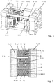
- an injection molding tool 3 is present on a plastics processing machine 1 as an injection molding machine 1.
- the plastic processing machine 1 as an injection molding machine 1 comprises a fixed plate 1.1 and a movable plate 1.2, which is known per se as a higher-level movement by means of hydraulic cylinders or an electric drive or another suitable linear drive can be moved and pressed onto the fixed plate 1.1 or moved away from it and thus at least the injection molding tool 3, which comprises a stationary tool half 3.1 and a movable tool half 3.2.
- the fixed tool half 3.1 is arranged on the fixed plate 1.1 and the movable tool half 3.2 is arranged on the movable plate 1.2.
- the fixed tool half 3.1 and the movable tool half 3.2 are arranged between the fixed plate 1.1 and the movable plate 1.2.
- the movable tool half 3.2 By moving the movable plate 1.2 in the direction of or away from the fixed plate 1.1, the movable tool half 3.2 is moved in the direction of or away from the fixed tool half 3.1, whereby the injection molding tool 3 closes and opens depending on the process step.
- the movement of the movable tool half 3.2 of the injection molding tool 3 is viewed in a simplified manner.
- RIM tools 5, 6, each with a movable and a fixed tool half 5.1, 5.2, 6.1, 6.2 are present in the specific exemplary embodiment.
- the fixed tool halves 5.1, 6.1 of the RIM tools 5, 6 are adjacent to the fixed tool half 3.1 of the injection molding tool 3 radially to the closing direction of the movable tool halves 3.2, 5.2, 6.2, i.e. at least laterally on both sides next to the fixed tool half 3.1 of the injection molding tool 3 arranged.
- the RIM tools 5, 6 can also be provided offset above or below the injection molding tool 3, not shown.
- the respective movable tool halves 5.2, 6.2 of the RIM tools 5, 6 can also be moved and pressed or moved away from one another by the superordinate movement of the movable plate 1.2 depending on the process step.
- the respective or relevant movement of the respective movable tool halves 5.2, 6.2 of the RIM tools 5, 6 depending on the process step is considered in relation to the movement of the movable tool half 3.2 of the injection molding tool 3, if applicable.
- the movable tool halves 5.2, 6.2 of the RIM tools 5, 6 are designed to be closable at the same time as the movable tool half 3.2 of the injection molding tool 3.
- the RIM tools 5, 5 are designed to be lockable independently of the injection molding tool 3, so that, on the one hand, each of the RIM tools 5, 6 is and remains closed regardless of the position of the injection molding tool 3 or its movable tool half 3.2 the movable tool half 3.2 of the injection molding tool 3 is moved for opening without or with at least one of the movable tool halves 5.2, 6.2 of the RIM tools 5, 6.
- the injection molding tool 3 alone or and at least one of the movable tool halves 5.2, 6.2 of the RIM tools 5, 6 can be moved, provided that the respective RIM process step enables or requires it.
- the fixed and movable tool halves 5.1, 5.2, 6.1, 6.2 of the respective RIM tools 5, 6 can be locked individually, so that on the one hand the fixed and movable tool halves 5.1, 5.2, 6.1, 6.2 can be locked to one another or to one another and thus independently of the The injection molding process is also locked and the respective RIM cavity for the RIM process step remains closed.
- electrical, mechanical, hydraulic, pneumatic or magnetic locks 13 can be used as the locking 13 in the parting plane of the movable and fixed tool halves 5.1, 5.2, 6.1, 6.2 of the respective RIM tools 5, 6, which the movable and fixed tool halves 5.1, 5.2, 6.1, 6.2 as required and reliably absorb the forces during the RIM process that arise from the filling pressure and the area of the cavity and keep the corresponding movable and fixed tool halves 5.1, 5.2, 6.1, 6.2 closed.
- the locking 13 or the locking system of the fixed and movable tool halves 5.1, 5.2, 6.1, 6.2 of the RIM tools 5, 6 can be divided by means of a implement mechanically driven wedge system or a hydraulically driven wedge system or a pneumatically driven wedge system or an electrically driven wedge system or by means of electromagnets.
- the respective movable tool halves 5.2, 6.2 of the RIM tools 5, 6 are coupled to the movable tool half 3.2 of the injection molding tool 3, so that the respective movable tool halves 5.2, 6.2 of the RIM tools 5, 6 depending on Process step can be moved together with the movable tool half 3.2 of the injection molding tool 3 for opening and closing.
- the respective movable tool halves 5.2, 6.2 of the RIM tools 5, 6 can also be coupled to another structural element of the plastics processing machine 1, which enables the respective opening and closing.
- the coupling 14 of the respective movable tool halves 5.2, 6.2 of the RIM tools 5, 6 with the movable tool half 3.2 of the injection molding tool 3 can be implemented indirectly, for example on a clamping plate 4 or base plate 4, or directly on one another.
- the respective movable tool half 5.2, 6.2 of the respective RIM tools 5, 6 is detachably coupled to the respective clamping plate 4 or base plate 4 with a mechanical, hydraulic, pneumatic or electrically driven coupling 14 or with a magnetic coupling 14, with reliable opening the respective RIM tools 5, 6 and a defined position of the opened respective movable tool half 5.2, 6.2 of the respective RIM tools 5, 6 must be taken into account.
- a coupling 14 of the respective movable tool half 5.2, 6.2 of the respective RIM tools 5, 6 with the movable tool half 3.2 of the injection molding tool 3 is also possible with a mechanical, hydraulic, pneumatic or electrically driven coupling 14 or with a magnetic coupling 14.
- the coupling system 14 for the coupling and decoupling of the movable tool half 5.2, 6.2 on the respective clamping plate 4 can be operated or implemented with a mechanical system, a hydraulically driven system, a pneumatically driven system, an electrically driven system or with an electromagnet.
- the respective movable tool halves 5.2, 6.2 of the RIM tools 5, 6 are arranged on a clamping plate 4 or base plate 4 shared with the movable tool half 3.2 of the injection molding tool 3, so that the respective lock 13 is in the parting plane of the tool half 5.1 , 5.2, 6.1, 6.2 of the RIM tool 5, 6 and the corresponding release of this lock 13 is implemented on and with the clamping plate 4 or base plate 4 depending on the process step.
- the movable tool half 5.2, 6.2 of the RIM tool 5, 6 is offset or simultaneously with the movable tool half 3.2 of the injection molding tool 3, for example via a corresponding additional drive not shown is designed to be movable in order to open the respective movable tool half 5.2, 6.2 of the RIM tool 5, 6 with a time offset.
- the respective movable tool half 5.2, 6.2 of the RIM tool 5, 6 can be moved individually according to the specific arrangement on the movable tool half 3.2 of the injection molding tool 3 or on its own or the common clamping plate 4 or base plate 4.
- the schematic representation in Figure 2 shows a plastics processing machine 1 in which an injection molding tool 3 is present, on which a number of structurally identical RIM tools 5, 6 are arranged that are matched to the respective cycle times.
- the respective locking system 13 has to absorb the forces that arise from the filling pressure and the area of the cavity.
- the respective clamping plates 4 of the RIM tools 5, 6 are firmly connected to the movable plate 1.2 of the injection molding machine 1.
- Each RIM tool 5, 6 can have its own clamping plate 4.
- the coupling system 14 enables the coupling 14 of the movable mold halves 5.2, 6.2 of the respective RIM tools 5, 6 with the respective clamping plate 4, at least for opening, in order to hold or release one side of the RIM tools 5, 6, i.e. the movable tool halves 5.2, 6.2, depending on the process step on the clamping plate 4, depending on whether the RIM tool 5, 6 has to remain closed or has to be opened or has to remain open for removing the finished component 12 and inserting the next blank 10.
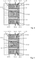
- the method according to the invention for the production of multi-component plastic molded parts wherein on a plastic processing machine 1 as an injection molding machine 1 in an injection molding tool 3, comprising a stationary tool half 3.1 and a movable tool half 3.2, plastic melt 10 for a blank 10 is injected and then on or around the Blank 10 in a RIM tool 5, 6, comprising a fixed tool half 5.1, 6.1 and a movable tool half 5.2, 6.2, a reactive component mixture 11 is injected, provides that, as Figure 3 shown, the tools 3, 5, 6 are closed in a first cycle and an injection molding process takes place in the injection molding tool 3 as, for example, the first injection molding process of the blank 10, as this Figure 4 is shown.
- the locks 13 of the stationary and the movable tool halves 5.1, 5.2, 6.1, 6.2 are inactive O.
- the coupling 14 in the parting plane of the tool half 5.2, 6.2 to the respective clamping plate 4 is active X.
- the closing of the injection molding tool 3 with the fixed tool half 3.1 and movable tool half 3.2 as well as the respective RIM tools 5, 6 with the fixed tool halves 5.1, 6.1 and the movable tool halves 5.2, 6.2 go with the closing of the plastics processing machine 1 as injection molding machine 1 by moving the movable plate 1.2 in the direction of the fixed plate 1.1 of the injection molding machine 1.
- At least the opening of the injection molding tool 3 goes with the opening of the plastics processing machine 1 as injection molding machine 1 by moving the movable plate 1.2 away from the fixed plate 1.1 of the injection molding machine 1 and thus with the movement of the movable tool half 3.2 away from the stationary tool half 3.1.
- the RIM tools 5, 6 can be adjusted individually and at least in accordance with the movement of the movable plate 1.2 of the injection molding machine 1 by moving the movable tool half 5.2, 6.2 and / or the movement of the movable tool half 3.2 of the injection molding tool 3.
- the opening and closing of the injection molding tool 3 or the movement of the movable tool half 3.2 which also means that the plastics processing machine 1 as an injection molding machine 1 also opens or closes or the movable plate 1.2 for Opening or closing is moved.
- the respective closing or opening movable tool halves 5.2, 6.2 of the respective RIM tool 5, 6 move depending on the process step or cycle corresponding to the movable tool half 3.2 of the injection molding tool 3.
- the movable tool halves 5.2, 6.2 of the respective RIM tool 5, 6 independently of the opening movable tool half 3.2 of the injection molding tool 3 on the stationary tool half 5.1, 6.1 of the respective RIM tool 5, 6.
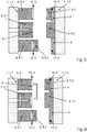
- the blank 10 as an injection molded part is, as in Figure 6 shown, transferred from the stationary tool half 3.1 of the injection molding tool 3 into the stationary tool half 5.1 of the first RIM tool 5, so for example removed from the stationary tool half 3.1 of the injection molding tool 3 and inserted into the stationary tool half 5.1. It is also possible for the injection-molded part to be transferred from the stationary tool half 3.1 of the injection molding tool 3 into the movable tool half 5.2 of the first RIM tool 5.
- the injection molding tool 3 and the first RIM tool 5 then close in a third cycle by moving the respective movable tool halves 3.2, 5.2.
- the injection molding of a blank 10 as a second injection molding process.
- the RIM process for a combined component 12 takes place in the first RIM tool 5.
- the locking 13 of the stationary and movable tool halves 5.1, 5.2 is active X.
- the coupling 14 in the parting plane of the tool half 5.2 to the respective clamping plate 4 is inactive O
- the second RIM tool 6 remains closed, the locks 13 of the stationary and the movable tool halves 6.1, 6.2 being active X and the coupling 14 in the parting plane of the tool half 6.2 to the respective clamping plate 4 being inactive O, the movable tool halves 6.2 from the Clamping plate 4 or base plate 4 is decoupled.
- the injection molding tool 3 and a second RIM tool 6 opened by moving the respective movable tool halves 3.2, 6.2 away from the stationary tool halves 3.1, 6.1.
- the lock 13 of the stationary and movable tool halves 6.1, 6.2 is inactive O and the coupling 14 in the parting plane of the tool half 6.2 to the respective clamping plate 4 is active X, so that the movable tool halves 6.2 are coupled to the clamping plate 4 or base plate 4.
- the first RIM tool 5 closed for the ongoing RIM process.
- the locking 13 of the fixed and the movable tool halves 5.1, 5.2 is active X.
- the coupling 14 in the parting plane of the tool half 5.2 to the respective clamping plate 4 is inactive O, so that the movable tool halves 5.2 are decoupled from the clamping plate 4 or base plate 4.
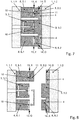
- the blank 10 is, as in Figure 8 shown, automatically transferred from the fixed or movable tool half 3.1, 3.2 of the injection molding tool 3 into the empty or emptied fixed or movable tool half 6.1, 6.2 of the second RIM tool 6.
- the fixed or movable tool half 6.1, 6.2 of the second RIM tool 6 may not be empty. It is therefore provided that, if necessary, the finished component 12 is removed from the stationary or movable tool half 6.1, 6.2 of the second or further RIM tool 6 in an automated manner for emptying, and thus the fixed or movable tool half 6.1, 6.2 is emptied and then the blank 10 is inserted into the emptied stationary tool half 6.1.
- the first RIM tool 5 closed for the ongoing RIM process.
- the locking 13 of the fixed and the movable tool halves 5.1, 5.2 is active X.
- the coupling 14 in the parting plane of the tool half 5.2 to the respective clamping plate 4 is inactive O, so that the movable tool halves 5.2 are decoupled from the clamping plate 4 or base plate 4.
- a RIM process is now running in each of the two RIM tools 5, 6.
- the sequence of the clocks forms a cycle that can run continuously.
- the injection molding tool 3 and the first RIM tool 5 opened by moving the respective movable mold halves 3.2, 5.2.
- the locking 13 of the stationary and the movable tool halves 5.1, 5.2 is inactive O and the coupling 14 in the parting plane of the tool half 5.2 to the respective clamping plate 4 is active X, so that the movable tool halves 5.2 are coupled to the clamping plate 4 or base plate 4.
- the second RIM tool 6 closed for the still ongoing RIM process.
- the lock 13 of the fixed and movable tool halves 6.1, 6.2 is active X.
- the coupling 14 in the parting plane of the tool half 6.2 to the respective clamping plate 4 is inactive O, so that the movable tool halves 6.2 are decoupled from the clamping plate 4 or base plate 4.
- the blank 10 is, as in Figure 10 shown, for example automatically transferred from the stationary tool half 3.1 of the injection molding tool 3 into the empty or emptied stationary tool half 5.1 of the first RIM tool 5, with the first finished component 12 of this cycle from the movable tool half 5.2 of the first RIM tool 5 is removed automatically.
- the injection molding tool 3 and the first RIM tool 5 are closed by moving the respective movable tool halves 3.2, 5.2.
- the injection molding of a blank 10 as a fourth injection molding process.
- the RIM process for a combined component 12 takes place in the first RIM tool 5.
- the second RIM tool 6 remains closed, with the locks 13 of the fixed and movable tool halves 6.1, 6.2 being active X and the coupling 14 in the parting plane the tool half 6.2 is inactive O to the respective clamping plate 4, the movable tool halves 6.2 are decoupled from the clamping plate 4 or base plate 4.
- the locking, unlocking, coupling or decoupling of the two RIM tools 5, 6 is the same as above Figure 7 or to the third bar.
- Figure 12 According to the fourth cycle, it is shown that the injection molding tool 3 and the second RIM tool 6 are opened by moving the respective movable tool halves 3.2, 6.2, while the first RIM tool 5 remains closed and the blank 10 is removed from the stationary tool half 3 , 1, of the injection molding tool 3 is automatically transferred into the empty or emptied stationary tool half 6.1, 6.2 of the second RIM tool 6.
- the finished component 12 is here automatically removed, for example, from the movable tool half 6.2 of the second RIM tool 6.
- the locking, unlocking, coupling or decoupling of the two RIM tools 5, 6 is the same as above Figure 8 or to the fourth bar.
- Tool halves 5.2, 6.2 of the respective RIM tool 5, 6 on the movable tool half 3.2 of the injection molding tool 3 or on another structural element of the plastics processing machine 1, such as a separate clamping plate 4 or a common clamping plate 4 on the movable tool half 3.2 of the injection molding Tool 3 takes place as a function of the injection molding cycle time and RIM cycle time, so that an adapted control for a synchronous movement of the respectively affected movable tool halves 3.2, 5.2, 6.2 is made possible.
- the transfer of the blank 10 produced by injection molding from the injection molding tool 3 into the RIM tools 5, 6 and the removal of the finished component 12 from the respective RIM tools 5, 6 can be carried out either manually or automatically.
- FIG 13 a plastics processing machine 1 is shown, in which an injection molding tool 3 is present on which a RIM tool 5 is arranged.
- a lock 13 or a locking system 13 in the parting plane of the RIM mold half 5.1, 5.2 in order to securely close the RIM tool 5 or the mold parting plane when the injection molding machine 1 and thus the injection molding tool 3 are open close. If an individual closing of the RIM tool 5 or the mold parting plane is not required, the lock 13 or the locking system 13 can be dispensed with, since this reduces the structural effort when using only one RIM tool 5. If a locking system 13 is present, it must absorb the forces that arise from the filling pressure and the area of the cavity.
- the clamping plate 4 of the RIM tool 5 is firmly connected to the movable plate 1.2 of the injection molding machine 1.
- This clamping plate 4 also has the task of receiving one side of the coupling system 14 that may be present.
- the RIM tool 5 can have its own clamping plate 4.
- the coupling system 14 which may be present enables the movable tool half 5.2 of the RIM tool 5 to be coupled to the clamping plate 4 at least for opening around one side of the RIM tool 5, 6, i.e.
- the movable tool half 5.2 depending on the process step on the clamping plate 4 to hold or to release, depending on whether the RIM tool 5 has to remain closed, if necessary, or to open or to remain open for the removal of the finished component 12 and the insertion of the next blank 10.
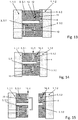
- the method according to the invention provides that for the production of multi-component plastic molded parts on a plastic processing machine 1 as an injection molding machine 1 in an injection molding tool 3, comprising a stationary tool half 3.1 and a movable tool half 3.2, plastic melt 10 for a blank 10 is injected and then a reactive component mixture 11 is injected on or around the blank 10 in a RIM tool 5 comprising a fixed tool half 5.1 and a movable tool half 5.2, with the tools 3, 5 being closed in a first cycle and an injection molding process in the injection molding tool 3 takes place as, for example, the first injection molding of the blank 10, like this Figure 14 is shown.
- the locks 13 of the stationary and movable tool halves 5.1, 5.2 are inactive O.
- the coupling 14 in the parting plane of the tool half 5.2, 6.2 to the respective clamping plate 4 is active X.
- the blank 10 as an injection molded part is, as in Figure 15 shown, transferred from the stationary tool half 3.1 of the injection molding tool 3 to the stationary tool half 5.1 of the RIM tool 5, so for example removed from the stationary tool half 3.1 of the injection molding tool 3 and inserted into the stationary tool half 5.1. It is also possible for the injection-molded part to be transferred from the stationary tool half 3.1 of the injection molding tool 3 into the movable tool half 5.2 of the RIM tool 5.
- the injection molding tool 3 and the RIM tool 5 close by moving the movable tool halves 3.2, 5.2.
- the injection molding tool 3 as in FIG Figure 16 shown, the injection molding of a blank 10 as a second injection molding process.
- the RIM process for a combined component 12 takes place in the RIM tool 5.
- the locking 13 of the stationary and movable tool halves 5.1, 5.2 is active X.
- the coupling 14 in the parting plane of the tool half 5.2 to the respective clamping plate 4 is inactive O, however, X can also remain active.
- the blank 10 is, as in Figure 17 shown, for example automatically transferred from the stationary tool half 3.1 of the injection molding tool 3 into the empty or emptied stationary tool half 5.1 of the first RIM tool 5, the first finished component 12 also automating this cycle from the movable tool half 5.2 of the RIM tool 5 is removed.
Landscapes
- Engineering & Computer Science (AREA)
- Mechanical Engineering (AREA)
- Manufacturing & Machinery (AREA)
- Moulds For Moulding Plastics Or The Like (AREA)
- Injection Moulding Of Plastics Or The Like (AREA)
Applications Claiming Priority (3)
| Application Number | Priority Date | Filing Date | Title |
|---|---|---|---|
| DE102019108646 | 2019-04-02 | ||
| DE102019124891 | 2019-09-16 | ||
| DE102020108596.6A DE102020108596A1 (de) | 2019-04-02 | 2020-03-27 | Verfahren und Vorrichtung zur Herstellung von mehrkomponentigen Kunststoffformteilen |
Publications (3)
| Publication Number | Publication Date |
|---|---|
| EP3718732A1 true EP3718732A1 (fr) | 2020-10-07 |
| EP3718732B1 EP3718732B1 (fr) | 2023-12-06 |
| EP3718732C0 EP3718732C0 (fr) | 2023-12-06 |
Family
ID=70057064
Family Applications (1)
| Application Number | Title | Priority Date | Filing Date |
|---|---|---|---|
| EP20167277.1A Active EP3718732B1 (fr) | 2019-04-02 | 2020-03-31 | Procédé et dispositif de fabrication des pièces moulées en matière plastique à plusieurs composants |
Country Status (1)
| Country | Link |
|---|---|
| EP (1) | EP3718732B1 (fr) |
Cited By (1)
| Publication number | Priority date | Publication date | Assignee | Title |
|---|---|---|---|---|
| EP3838548A1 (fr) * | 2019-12-19 | 2021-06-23 | Yizumi Precision Machinery (Suzhou) Co., Ltd | Machine de moulage par injection multi-matériaux et son procédé de moulage par injection multi-matériaux |
Citations (11)
| Publication number | Priority date | Publication date | Assignee | Title |
|---|---|---|---|---|
| US3898030A (en) * | 1973-06-25 | 1975-08-05 | Koehring Co | Injection-mold clamping unit having alternately ejecting die assemblies |
| DE19650854C1 (de) * | 1996-11-27 | 1998-03-12 | Petri Ag | Verfahren und Vorrichtung zur Herstellung eines Mehrschicht-Kunststoffteils |
| EP0903213A2 (fr) * | 1997-08-19 | 1999-03-24 | Universal Ventures | Repositionnement d'articles entre des positions différentes dans un espace accessible par intermittence |
| US20040094866A1 (en) | 2002-11-18 | 2004-05-20 | Boucherie Bart Gerard | Method and device for manufacturing injection molding pieces |
| DE102005013975A1 (de) | 2005-03-26 | 2006-09-28 | Krauss-Maffei Kunststofftechnik Gmbh | Vorrichtung und Verfahren zur Herstellung von optischen Datenträgern sowie optische Datenträger |
| DE102006021021A1 (de) * | 2006-05-05 | 2007-11-15 | Krauss Maffei Gmbh | Verfahren zur Herstellung eines Mehrschichtteiles |
| DE102006024481A1 (de) | 2006-05-26 | 2007-11-29 | Krauss Maffei Gmbh | Schließvorrichtung mit zwei Schiebetischen |
| DE102007051701A1 (de) * | 2007-10-30 | 2009-05-07 | Kraussmaffei Technologies Gmbh | Vorrichtung und Verfahren zur Herstellung mehrkomponentiger Kunststoff-Formteile |
| EP2004380B1 (fr) | 2006-04-06 | 2011-06-29 | KraussMaffei Technologies GmbH | Procede et dispositif de fabrication de pieces moulees en matiere synthetique a plusieurs composants |
| DE102011117267A1 (de) * | 2011-10-28 | 2013-05-02 | Kraussmaffei Technologies Gmbh | Verfahren und Vorrichtung zur Herstellung von beschichteten Formteilen |
| DE202019104347U1 (de) | 2019-08-07 | 2019-09-20 | Wellhöfer Treppen GmbH & Co. KG | Ausziehbare Treppe mit Einziehhilfe |
Family Cites Families (3)
| Publication number | Priority date | Publication date | Assignee | Title |
|---|---|---|---|---|
| US20030197307A1 (en) * | 2002-03-14 | 2003-10-23 | Akihiro Kitamura | Method for the injection molding and successive decoration molding for a molded product |
| DE102004062510A1 (de) * | 2004-12-24 | 2006-07-06 | Bayer Materialscience Ag | Verfahren zum Formen und Beschichten eines Substrats |
| DE202016104347U1 (de) * | 2016-03-07 | 2016-08-25 | Kraussmaffei Technologies Gmbh | Spritzgießmaschine zum Herstellen eines Mehrkomponenten-Kunststoffteils |
-
2020
- 2020-03-31 EP EP20167277.1A patent/EP3718732B1/fr active Active
Patent Citations (11)
| Publication number | Priority date | Publication date | Assignee | Title |
|---|---|---|---|---|
| US3898030A (en) * | 1973-06-25 | 1975-08-05 | Koehring Co | Injection-mold clamping unit having alternately ejecting die assemblies |
| DE19650854C1 (de) * | 1996-11-27 | 1998-03-12 | Petri Ag | Verfahren und Vorrichtung zur Herstellung eines Mehrschicht-Kunststoffteils |
| EP0903213A2 (fr) * | 1997-08-19 | 1999-03-24 | Universal Ventures | Repositionnement d'articles entre des positions différentes dans un espace accessible par intermittence |
| US20040094866A1 (en) | 2002-11-18 | 2004-05-20 | Boucherie Bart Gerard | Method and device for manufacturing injection molding pieces |
| DE102005013975A1 (de) | 2005-03-26 | 2006-09-28 | Krauss-Maffei Kunststofftechnik Gmbh | Vorrichtung und Verfahren zur Herstellung von optischen Datenträgern sowie optische Datenträger |
| EP2004380B1 (fr) | 2006-04-06 | 2011-06-29 | KraussMaffei Technologies GmbH | Procede et dispositif de fabrication de pieces moulees en matiere synthetique a plusieurs composants |
| DE102006021021A1 (de) * | 2006-05-05 | 2007-11-15 | Krauss Maffei Gmbh | Verfahren zur Herstellung eines Mehrschichtteiles |
| DE102006024481A1 (de) | 2006-05-26 | 2007-11-29 | Krauss Maffei Gmbh | Schließvorrichtung mit zwei Schiebetischen |
| DE102007051701A1 (de) * | 2007-10-30 | 2009-05-07 | Kraussmaffei Technologies Gmbh | Vorrichtung und Verfahren zur Herstellung mehrkomponentiger Kunststoff-Formteile |
| DE102011117267A1 (de) * | 2011-10-28 | 2013-05-02 | Kraussmaffei Technologies Gmbh | Verfahren und Vorrichtung zur Herstellung von beschichteten Formteilen |
| DE202019104347U1 (de) | 2019-08-07 | 2019-09-20 | Wellhöfer Treppen GmbH & Co. KG | Ausziehbare Treppe mit Einziehhilfe |
Cited By (1)
| Publication number | Priority date | Publication date | Assignee | Title |
|---|---|---|---|---|
| EP3838548A1 (fr) * | 2019-12-19 | 2021-06-23 | Yizumi Precision Machinery (Suzhou) Co., Ltd | Machine de moulage par injection multi-matériaux et son procédé de moulage par injection multi-matériaux |
Also Published As
| Publication number | Publication date |
|---|---|
| EP3718732B1 (fr) | 2023-12-06 |
| EP3718732C0 (fr) | 2023-12-06 |
Similar Documents
| Publication | Publication Date | Title |
|---|---|---|
| DE69713533T2 (de) | Revolvermaschine zum Formen von Gegenständen | |
| EP2292405B1 (fr) | Procédé et dispositif de montage et/ou de démontage de moules de soufflage | |
| EP0293665A2 (fr) | Procédé et appareil pour la fabrication de brosses en matériau plastique | |
| DE10347638A1 (de) | Horizontal-Spritzgießmaschine mit Dreheinrichtung | |
| WO2008040437A1 (fr) | Outil de coulage par injection de matière synthétique | |
| DE68921902T2 (de) | Sequentielle Spritzgiessmaschine. | |
| EP1494842B1 (fr) | Dispositif pour mouler par injection des corps moules en matiere plastique | |
| DE102020108596A1 (de) | Verfahren und Vorrichtung zur Herstellung von mehrkomponentigen Kunststoffformteilen | |
| DE102007051701A1 (de) | Vorrichtung und Verfahren zur Herstellung mehrkomponentiger Kunststoff-Formteile | |
| AT525769B1 (de) | Schließeinheit für eine Formgebungsmaschine | |
| EP3718732B1 (fr) | Procédé et dispositif de fabrication des pièces moulées en matière plastique à plusieurs composants | |
| EP3498451B1 (fr) | Machine de moulage par soufflage à accouplement de sol pouvant être actionné automatiquement | |
| EP2032327B1 (fr) | Dispositif de fermeture pour presse d'injection | |
| DE3733873A1 (de) | Presswerkzeug fuer kunststofformteile | |
| DE102011118970A1 (de) | Verriegelungsvorrichtung für Holme einer Kunststoffverarbeitungsmaschine | |
| DE202021004448U1 (de) | Spritzgusssystem und Fertigungssystem zur Herstellung von Formteilen aus spritzfähigen oder schäumfähigen Formmassen | |
| EP1858682A1 (fr) | Dispositif pour recevoir un moule | |
| DE3717760A1 (de) | Einrichtung zum kuppeln von energieanschluessen beim wechseln und spannen von formwerkzeugen | |
| AT526511B1 (de) | Schließeinheit sowie eine Formgebungsmaschine mit einer solchen Schließeinheit | |
| EP3871855B1 (fr) | Système de transfert avec un dispositif d'injection intégré sur une table de livraison | |
| DE10212044A1 (de) | Schließeinheit für eine Spritzgießmaschine | |
| EP4414155A1 (fr) | Unité de moulage par soufflage pour une installation de moulage par soufflage | |
| DE1729154A1 (de) | Formschliess- und -oeffnungsvorrichtung fuer Spritzgiessmaschinen | |
| DE102023103378A1 (de) | Blasformeinheit für eine Blasformanlage | |
| DE19918709A1 (de) | Werkzeugmodul für eine Spritzblasmaschine und Verfahren zum Betreiben dieser Maschine |
Legal Events
| Date | Code | Title | Description |
|---|---|---|---|
| PUAI | Public reference made under article 153(3) epc to a published international application that has entered the european phase |
Free format text: ORIGINAL CODE: 0009012 |
|
| STAA | Information on the status of an ep patent application or granted ep patent |
Free format text: STATUS: THE APPLICATION HAS BEEN PUBLISHED |
|
| AK | Designated contracting states |
Kind code of ref document: A1 Designated state(s): AL AT BE BG CH CY CZ DE DK EE ES FI FR GB GR HR HU IE IS IT LI LT LU LV MC MK MT NL NO PL PT RO RS SE SI SK SM TR |
|
| AX | Request for extension of the european patent |
Extension state: BA ME |
|
| STAA | Information on the status of an ep patent application or granted ep patent |
Free format text: STATUS: REQUEST FOR EXAMINATION WAS MADE |
|
| 17P | Request for examination filed |
Effective date: 20210401 |
|
| RBV | Designated contracting states (corrected) |
Designated state(s): AL AT BE BG CH CY CZ DE DK EE ES FI FR GB GR HR HU IE IS IT LI LT LU LV MC MK MT NL NO PL PT RO RS SE SI SK SM TR |
|
| STAA | Information on the status of an ep patent application or granted ep patent |
Free format text: STATUS: EXAMINATION IS IN PROGRESS |
|
| 17Q | First examination report despatched |
Effective date: 20221118 |
|
| GRAP | Despatch of communication of intention to grant a patent |
Free format text: ORIGINAL CODE: EPIDOSNIGR1 |
|
| STAA | Information on the status of an ep patent application or granted ep patent |
Free format text: STATUS: GRANT OF PATENT IS INTENDED |
|
| INTG | Intention to grant announced |
Effective date: 20230623 |
|
| RIC1 | Information provided on ipc code assigned before grant |
Ipc: B29L 9/00 20060101ALN20230615BHEP Ipc: B29K 75/00 20060101ALN20230615BHEP Ipc: B29C 45/64 20060101ALI20230615BHEP Ipc: B29C 45/12 20060101ALI20230615BHEP Ipc: B29C 67/24 20060101ALI20230615BHEP Ipc: B29C 45/16 20060101AFI20230615BHEP |
|
| GRAS | Grant fee paid |
Free format text: ORIGINAL CODE: EPIDOSNIGR3 |
|
| GRAA | (expected) grant |
Free format text: ORIGINAL CODE: 0009210 |
|
| STAA | Information on the status of an ep patent application or granted ep patent |
Free format text: STATUS: THE PATENT HAS BEEN GRANTED |
|
| AK | Designated contracting states |
Kind code of ref document: B1 Designated state(s): AL AT BE BG CH CY CZ DE DK EE ES FI FR GB GR HR HU IE IS IT LI LT LU LV MC MK MT NL NO PL PT RO RS SE SI SK SM TR |
|
| REG | Reference to a national code |
Ref country code: GB Ref legal event code: FG4D Free format text: NOT ENGLISH |
|
| REG | Reference to a national code |
Ref country code: CH Ref legal event code: EP |
|
| REG | Reference to a national code |
Ref country code: DE Ref legal event code: R096 Ref document number: 502020006252 Country of ref document: DE |
|
| REG | Reference to a national code |
Ref country code: IE Ref legal event code: FG4D Free format text: LANGUAGE OF EP DOCUMENT: GERMAN |
|
| U01 | Request for unitary effect filed |
Effective date: 20240105 |
|
| U07 | Unitary effect registered |
Designated state(s): AT BE BG DE DK EE FI FR IT LT LU LV MT NL PT SE SI Effective date: 20240115 |
|
| PG25 | Lapsed in a contracting state [announced via postgrant information from national office to epo] |
Ref country code: GR Free format text: LAPSE BECAUSE OF FAILURE TO SUBMIT A TRANSLATION OF THE DESCRIPTION OR TO PAY THE FEE WITHIN THE PRESCRIBED TIME-LIMIT Effective date: 20240307 |
|
| PG25 | Lapsed in a contracting state [announced via postgrant information from national office to epo] |
Ref country code: ES Free format text: LAPSE BECAUSE OF FAILURE TO SUBMIT A TRANSLATION OF THE DESCRIPTION OR TO PAY THE FEE WITHIN THE PRESCRIBED TIME-LIMIT Effective date: 20231206 |
|
| PG25 | Lapsed in a contracting state [announced via postgrant information from national office to epo] |
Ref country code: GR Free format text: LAPSE BECAUSE OF FAILURE TO SUBMIT A TRANSLATION OF THE DESCRIPTION OR TO PAY THE FEE WITHIN THE PRESCRIBED TIME-LIMIT Effective date: 20240307 Ref country code: ES Free format text: LAPSE BECAUSE OF FAILURE TO SUBMIT A TRANSLATION OF THE DESCRIPTION OR TO PAY THE FEE WITHIN THE PRESCRIBED TIME-LIMIT Effective date: 20231206 |
|
| U20 | Renewal fee for the european patent with unitary effect paid |
Year of fee payment: 5 Effective date: 20240327 |
|
| PG25 | Lapsed in a contracting state [announced via postgrant information from national office to epo] |
Ref country code: RS Free format text: LAPSE BECAUSE OF FAILURE TO SUBMIT A TRANSLATION OF THE DESCRIPTION OR TO PAY THE FEE WITHIN THE PRESCRIBED TIME-LIMIT Effective date: 20231206 Ref country code: NO Free format text: LAPSE BECAUSE OF FAILURE TO SUBMIT A TRANSLATION OF THE DESCRIPTION OR TO PAY THE FEE WITHIN THE PRESCRIBED TIME-LIMIT Effective date: 20240306 Ref country code: HR Free format text: LAPSE BECAUSE OF FAILURE TO SUBMIT A TRANSLATION OF THE DESCRIPTION OR TO PAY THE FEE WITHIN THE PRESCRIBED TIME-LIMIT Effective date: 20231206 |
|
| PG25 | Lapsed in a contracting state [announced via postgrant information from national office to epo] |
Ref country code: IS Free format text: LAPSE BECAUSE OF FAILURE TO SUBMIT A TRANSLATION OF THE DESCRIPTION OR TO PAY THE FEE WITHIN THE PRESCRIBED TIME-LIMIT Effective date: 20240406 |
|
| PG25 | Lapsed in a contracting state [announced via postgrant information from national office to epo] |
Ref country code: CZ Free format text: LAPSE BECAUSE OF FAILURE TO SUBMIT A TRANSLATION OF THE DESCRIPTION OR TO PAY THE FEE WITHIN THE PRESCRIBED TIME-LIMIT Effective date: 20231206 |
|
| PG25 | Lapsed in a contracting state [announced via postgrant information from national office to epo] |
Ref country code: SK Free format text: LAPSE BECAUSE OF FAILURE TO SUBMIT A TRANSLATION OF THE DESCRIPTION OR TO PAY THE FEE WITHIN THE PRESCRIBED TIME-LIMIT Effective date: 20231206 |
|
| PG25 | Lapsed in a contracting state [announced via postgrant information from national office to epo] |
Ref country code: SM Free format text: LAPSE BECAUSE OF FAILURE TO SUBMIT A TRANSLATION OF THE DESCRIPTION OR TO PAY THE FEE WITHIN THE PRESCRIBED TIME-LIMIT Effective date: 20231206 Ref country code: SK Free format text: LAPSE BECAUSE OF FAILURE TO SUBMIT A TRANSLATION OF THE DESCRIPTION OR TO PAY THE FEE WITHIN THE PRESCRIBED TIME-LIMIT Effective date: 20231206 Ref country code: RO Free format text: LAPSE BECAUSE OF FAILURE TO SUBMIT A TRANSLATION OF THE DESCRIPTION OR TO PAY THE FEE WITHIN THE PRESCRIBED TIME-LIMIT Effective date: 20231206 Ref country code: IS Free format text: LAPSE BECAUSE OF FAILURE TO SUBMIT A TRANSLATION OF THE DESCRIPTION OR TO PAY THE FEE WITHIN THE PRESCRIBED TIME-LIMIT Effective date: 20240406 Ref country code: CZ Free format text: LAPSE BECAUSE OF FAILURE TO SUBMIT A TRANSLATION OF THE DESCRIPTION OR TO PAY THE FEE WITHIN THE PRESCRIBED TIME-LIMIT Effective date: 20231206 |
|
| PG25 | Lapsed in a contracting state [announced via postgrant information from national office to epo] |
Ref country code: PL Free format text: LAPSE BECAUSE OF FAILURE TO SUBMIT A TRANSLATION OF THE DESCRIPTION OR TO PAY THE FEE WITHIN THE PRESCRIBED TIME-LIMIT Effective date: 20231206 |
|
| PG25 | Lapsed in a contracting state [announced via postgrant information from national office to epo] |
Ref country code: PL Free format text: LAPSE BECAUSE OF FAILURE TO SUBMIT A TRANSLATION OF THE DESCRIPTION OR TO PAY THE FEE WITHIN THE PRESCRIBED TIME-LIMIT Effective date: 20231206 |
|
| REG | Reference to a national code |
Ref country code: DE Ref legal event code: R097 Ref document number: 502020006252 Country of ref document: DE |
|
| PLBE | No opposition filed within time limit |
Free format text: ORIGINAL CODE: 0009261 |
|
| STAA | Information on the status of an ep patent application or granted ep patent |
Free format text: STATUS: NO OPPOSITION FILED WITHIN TIME LIMIT |
|
| REG | Reference to a national code |
Ref country code: CH Ref legal event code: PL |
|
| 26N | No opposition filed |
Effective date: 20240909 |
|
| PG25 | Lapsed in a contracting state [announced via postgrant information from national office to epo] |
Ref country code: MC Free format text: LAPSE BECAUSE OF FAILURE TO SUBMIT A TRANSLATION OF THE DESCRIPTION OR TO PAY THE FEE WITHIN THE PRESCRIBED TIME-LIMIT Effective date: 20231206 |
|
| GBPC | Gb: european patent ceased through non-payment of renewal fee |
Effective date: 20240331 |
|
| PG25 | Lapsed in a contracting state [announced via postgrant information from national office to epo] |
Ref country code: MC Free format text: LAPSE BECAUSE OF FAILURE TO SUBMIT A TRANSLATION OF THE DESCRIPTION OR TO PAY THE FEE WITHIN THE PRESCRIBED TIME-LIMIT Effective date: 20231206 |
|
| PG25 | Lapsed in a contracting state [announced via postgrant information from national office to epo] |
Ref country code: GB Free format text: LAPSE BECAUSE OF NON-PAYMENT OF DUE FEES Effective date: 20240331 |
|
| PG25 | Lapsed in a contracting state [announced via postgrant information from national office to epo] |
Ref country code: IE Free format text: LAPSE BECAUSE OF NON-PAYMENT OF DUE FEES Effective date: 20240331 |
|
| PG25 | Lapsed in a contracting state [announced via postgrant information from national office to epo] |
Ref country code: IE Free format text: LAPSE BECAUSE OF NON-PAYMENT OF DUE FEES Effective date: 20240331 Ref country code: GB Free format text: LAPSE BECAUSE OF NON-PAYMENT OF DUE FEES Effective date: 20240331 Ref country code: CH Free format text: LAPSE BECAUSE OF NON-PAYMENT OF DUE FEES Effective date: 20240331 |
|
| U1N | Appointed representative for the unitary patent procedure changed after the registration of the unitary effect |
Representative=s name: SCHIED, SEBASTIAN; DE |
|
| U20 | Renewal fee for the european patent with unitary effect paid |
Year of fee payment: 6 Effective date: 20250325 |
|
| PG25 | Lapsed in a contracting state [announced via postgrant information from national office to epo] |
Ref country code: CY Free format text: LAPSE BECAUSE OF FAILURE TO SUBMIT A TRANSLATION OF THE DESCRIPTION OR TO PAY THE FEE WITHIN THE PRESCRIBED TIME-LIMIT; INVALID AB INITIO Effective date: 20200331 |
|
| PG25 | Lapsed in a contracting state [announced via postgrant information from national office to epo] |
Ref country code: HU Free format text: LAPSE BECAUSE OF FAILURE TO SUBMIT A TRANSLATION OF THE DESCRIPTION OR TO PAY THE FEE WITHIN THE PRESCRIBED TIME-LIMIT; INVALID AB INITIO Effective date: 20200331 |
|
| PG25 | Lapsed in a contracting state [announced via postgrant information from national office to epo] |
Ref country code: TR Free format text: LAPSE BECAUSE OF FAILURE TO SUBMIT A TRANSLATION OF THE DESCRIPTION OR TO PAY THE FEE WITHIN THE PRESCRIBED TIME-LIMIT Effective date: 20231206 |
|
| U20 | Renewal fee for the european patent with unitary effect paid |
Year of fee payment: 7 Effective date: 20260330 |