EP2543534A1 - Dispositif de stockage d'énergie à sécurité améliorée, véhicule automobile comprennant un tel dispositiv et procédé de tenir en fonction un dispositif de stockage d'énergie - Google Patents
Dispositif de stockage d'énergie à sécurité améliorée, véhicule automobile comprennant un tel dispositiv et procédé de tenir en fonction un dispositif de stockage d'énergie Download PDFInfo
- Publication number
- EP2543534A1 EP2543534A1 EP11173272A EP11173272A EP2543534A1 EP 2543534 A1 EP2543534 A1 EP 2543534A1 EP 11173272 A EP11173272 A EP 11173272A EP 11173272 A EP11173272 A EP 11173272A EP 2543534 A1 EP2543534 A1 EP 2543534A1
- Authority
- EP
- European Patent Office
- Prior art keywords
- energy storage
- storage device
- switching device
- storage elements
- state
- Prior art date
- Legal status (The legal status is an assumption and is not a legal conclusion. Google has not performed a legal analysis and makes no representation as to the accuracy of the status listed.)
- Withdrawn
Links
- 238000004146 energy storage Methods 0.000 title claims abstract description 93
- 238000000034 method Methods 0.000 title claims abstract description 7
- 239000003990 capacitor Substances 0.000 claims description 7
- 230000001133 acceleration Effects 0.000 claims description 3
- 239000002360 explosive Substances 0.000 claims description 3
- 238000000926 separation method Methods 0.000 description 4
- 238000010586 diagram Methods 0.000 description 2
- 230000001960 triggered effect Effects 0.000 description 2
- 230000032683 aging Effects 0.000 description 1
- 230000015572 biosynthetic process Effects 0.000 description 1
- 238000009795 derivation Methods 0.000 description 1
- 230000018109 developmental process Effects 0.000 description 1
- 238000007599 discharging Methods 0.000 description 1
- 230000000694 effects Effects 0.000 description 1
- 230000005611 electricity Effects 0.000 description 1
- 238000004880 explosion Methods 0.000 description 1
- 230000002427 irreversible effect Effects 0.000 description 1
- 238000005096 rolling process Methods 0.000 description 1
- 230000035939 shock Effects 0.000 description 1
- 230000035882 stress Effects 0.000 description 1
Images

Classifications
-
- B—PERFORMING OPERATIONS; TRANSPORTING
- B60—VEHICLES IN GENERAL
- B60K—ARRANGEMENT OR MOUNTING OF PROPULSION UNITS OR OF TRANSMISSIONS IN VEHICLES; ARRANGEMENT OR MOUNTING OF PLURAL DIVERSE PRIME-MOVERS IN VEHICLES; AUXILIARY DRIVES FOR VEHICLES; INSTRUMENTATION OR DASHBOARDS FOR VEHICLES; ARRANGEMENTS IN CONNECTION WITH COOLING, AIR INTAKE, GAS EXHAUST OR FUEL SUPPLY OF PROPULSION UNITS IN VEHICLES
- B60K1/00—Arrangement or mounting of electrical propulsion units
- B60K1/04—Arrangement or mounting of electrical propulsion units of the electric storage means for propulsion
-
- B—PERFORMING OPERATIONS; TRANSPORTING
- B60—VEHICLES IN GENERAL
- B60L—PROPULSION OF ELECTRICALLY-PROPELLED VEHICLES; SUPPLYING ELECTRIC POWER FOR AUXILIARY EQUIPMENT OF ELECTRICALLY-PROPELLED VEHICLES; ELECTRODYNAMIC BRAKE SYSTEMS FOR VEHICLES IN GENERAL; MAGNETIC SUSPENSION OR LEVITATION FOR VEHICLES; MONITORING OPERATING VARIABLES OF ELECTRICALLY-PROPELLED VEHICLES; ELECTRIC SAFETY DEVICES FOR ELECTRICALLY-PROPELLED VEHICLES
- B60L3/00—Electric devices on electrically-propelled vehicles for safety purposes; Monitoring operating variables, e.g. speed, deceleration or energy consumption
- B60L3/0007—Measures or means for preventing or attenuating collisions
-
- B—PERFORMING OPERATIONS; TRANSPORTING
- B60—VEHICLES IN GENERAL
- B60L—PROPULSION OF ELECTRICALLY-PROPELLED VEHICLES; SUPPLYING ELECTRIC POWER FOR AUXILIARY EQUIPMENT OF ELECTRICALLY-PROPELLED VEHICLES; ELECTRODYNAMIC BRAKE SYSTEMS FOR VEHICLES IN GENERAL; MAGNETIC SUSPENSION OR LEVITATION FOR VEHICLES; MONITORING OPERATING VARIABLES OF ELECTRICALLY-PROPELLED VEHICLES; ELECTRIC SAFETY DEVICES FOR ELECTRICALLY-PROPELLED VEHICLES
- B60L3/00—Electric devices on electrically-propelled vehicles for safety purposes; Monitoring operating variables, e.g. speed, deceleration or energy consumption
- B60L3/0023—Detecting, eliminating, remedying or compensating for drive train abnormalities, e.g. failures within the drive train
- B60L3/0069—Detecting, eliminating, remedying or compensating for drive train abnormalities, e.g. failures within the drive train relating to the isolation, e.g. ground fault or leak current
-
- B—PERFORMING OPERATIONS; TRANSPORTING
- B60—VEHICLES IN GENERAL
- B60L—PROPULSION OF ELECTRICALLY-PROPELLED VEHICLES; SUPPLYING ELECTRIC POWER FOR AUXILIARY EQUIPMENT OF ELECTRICALLY-PROPELLED VEHICLES; ELECTRODYNAMIC BRAKE SYSTEMS FOR VEHICLES IN GENERAL; MAGNETIC SUSPENSION OR LEVITATION FOR VEHICLES; MONITORING OPERATING VARIABLES OF ELECTRICALLY-PROPELLED VEHICLES; ELECTRIC SAFETY DEVICES FOR ELECTRICALLY-PROPELLED VEHICLES
- B60L3/00—Electric devices on electrically-propelled vehicles for safety purposes; Monitoring operating variables, e.g. speed, deceleration or energy consumption
- B60L3/04—Cutting off the power supply under fault conditions
-
- B—PERFORMING OPERATIONS; TRANSPORTING
- B60—VEHICLES IN GENERAL
- B60L—PROPULSION OF ELECTRICALLY-PROPELLED VEHICLES; SUPPLYING ELECTRIC POWER FOR AUXILIARY EQUIPMENT OF ELECTRICALLY-PROPELLED VEHICLES; ELECTRODYNAMIC BRAKE SYSTEMS FOR VEHICLES IN GENERAL; MAGNETIC SUSPENSION OR LEVITATION FOR VEHICLES; MONITORING OPERATING VARIABLES OF ELECTRICALLY-PROPELLED VEHICLES; ELECTRIC SAFETY DEVICES FOR ELECTRICALLY-PROPELLED VEHICLES
- B60L50/00—Electric propulsion with power supplied within the vehicle
- B60L50/40—Electric propulsion with power supplied within the vehicle using propulsion power supplied by capacitors
-
- B—PERFORMING OPERATIONS; TRANSPORTING
- B60—VEHICLES IN GENERAL
- B60L—PROPULSION OF ELECTRICALLY-PROPELLED VEHICLES; SUPPLYING ELECTRIC POWER FOR AUXILIARY EQUIPMENT OF ELECTRICALLY-PROPELLED VEHICLES; ELECTRODYNAMIC BRAKE SYSTEMS FOR VEHICLES IN GENERAL; MAGNETIC SUSPENSION OR LEVITATION FOR VEHICLES; MONITORING OPERATING VARIABLES OF ELECTRICALLY-PROPELLED VEHICLES; ELECTRIC SAFETY DEVICES FOR ELECTRICALLY-PROPELLED VEHICLES
- B60L50/00—Electric propulsion with power supplied within the vehicle
- B60L50/50—Electric propulsion with power supplied within the vehicle using propulsion power supplied by batteries or fuel cells
- B60L50/51—Electric propulsion with power supplied within the vehicle using propulsion power supplied by batteries or fuel cells characterised by AC-motors
-
- B—PERFORMING OPERATIONS; TRANSPORTING
- B60—VEHICLES IN GENERAL
- B60L—PROPULSION OF ELECTRICALLY-PROPELLED VEHICLES; SUPPLYING ELECTRIC POWER FOR AUXILIARY EQUIPMENT OF ELECTRICALLY-PROPELLED VEHICLES; ELECTRODYNAMIC BRAKE SYSTEMS FOR VEHICLES IN GENERAL; MAGNETIC SUSPENSION OR LEVITATION FOR VEHICLES; MONITORING OPERATING VARIABLES OF ELECTRICALLY-PROPELLED VEHICLES; ELECTRIC SAFETY DEVICES FOR ELECTRICALLY-PROPELLED VEHICLES
- B60L58/00—Methods or circuit arrangements for monitoring or controlling batteries or fuel cells, specially adapted for electric vehicles
- B60L58/10—Methods or circuit arrangements for monitoring or controlling batteries or fuel cells, specially adapted for electric vehicles for monitoring or controlling batteries
- B60L58/18—Methods or circuit arrangements for monitoring or controlling batteries or fuel cells, specially adapted for electric vehicles for monitoring or controlling batteries of two or more battery modules
-
- B—PERFORMING OPERATIONS; TRANSPORTING
- B60—VEHICLES IN GENERAL
- B60L—PROPULSION OF ELECTRICALLY-PROPELLED VEHICLES; SUPPLYING ELECTRIC POWER FOR AUXILIARY EQUIPMENT OF ELECTRICALLY-PROPELLED VEHICLES; ELECTRODYNAMIC BRAKE SYSTEMS FOR VEHICLES IN GENERAL; MAGNETIC SUSPENSION OR LEVITATION FOR VEHICLES; MONITORING OPERATING VARIABLES OF ELECTRICALLY-PROPELLED VEHICLES; ELECTRIC SAFETY DEVICES FOR ELECTRICALLY-PROPELLED VEHICLES
- B60L58/00—Methods or circuit arrangements for monitoring or controlling batteries or fuel cells, specially adapted for electric vehicles
- B60L58/10—Methods or circuit arrangements for monitoring or controlling batteries or fuel cells, specially adapted for electric vehicles for monitoring or controlling batteries
- B60L58/18—Methods or circuit arrangements for monitoring or controlling batteries or fuel cells, specially adapted for electric vehicles for monitoring or controlling batteries of two or more battery modules
- B60L58/21—Methods or circuit arrangements for monitoring or controlling batteries or fuel cells, specially adapted for electric vehicles for monitoring or controlling batteries of two or more battery modules having the same nominal voltage
-
- H—ELECTRICITY
- H01—ELECTRIC ELEMENTS
- H01M—PROCESSES OR MEANS, e.g. BATTERIES, FOR THE DIRECT CONVERSION OF CHEMICAL ENERGY INTO ELECTRICAL ENERGY
- H01M10/00—Secondary cells; Manufacture thereof
- H01M10/42—Methods or arrangements for servicing or maintenance of secondary cells or secondary half-cells
- H01M10/4207—Methods or arrangements for servicing or maintenance of secondary cells or secondary half-cells for several batteries or cells simultaneously or sequentially
-
- H—ELECTRICITY
- H01—ELECTRIC ELEMENTS
- H01M—PROCESSES OR MEANS, e.g. BATTERIES, FOR THE DIRECT CONVERSION OF CHEMICAL ENERGY INTO ELECTRICAL ENERGY
- H01M10/00—Secondary cells; Manufacture thereof
- H01M10/42—Methods or arrangements for servicing or maintenance of secondary cells or secondary half-cells
- H01M10/425—Structural combination with electronic components, e.g. electronic circuits integrated to the outside of the casing
-
- H—ELECTRICITY
- H01—ELECTRIC ELEMENTS
- H01M—PROCESSES OR MEANS, e.g. BATTERIES, FOR THE DIRECT CONVERSION OF CHEMICAL ENERGY INTO ELECTRICAL ENERGY
- H01M10/00—Secondary cells; Manufacture thereof
- H01M10/42—Methods or arrangements for servicing or maintenance of secondary cells or secondary half-cells
- H01M10/48—Accumulators combined with arrangements for measuring, testing or indicating the condition of cells, e.g. the level or density of the electrolyte
- H01M10/482—Accumulators combined with arrangements for measuring, testing or indicating the condition of cells, e.g. the level or density of the electrolyte for several batteries or cells simultaneously or sequentially
-
- H—ELECTRICITY
- H01—ELECTRIC ELEMENTS
- H01M—PROCESSES OR MEANS, e.g. BATTERIES, FOR THE DIRECT CONVERSION OF CHEMICAL ENERGY INTO ELECTRICAL ENERGY
- H01M50/00—Constructional details or processes of manufacture of the non-active parts of electrochemical cells other than fuel cells, e.g. hybrid cells
- H01M50/50—Current conducting connections for cells or batteries
- H01M50/572—Means for preventing undesired use or discharge
- H01M50/574—Devices or arrangements for the interruption of current
-
- B—PERFORMING OPERATIONS; TRANSPORTING
- B60—VEHICLES IN GENERAL
- B60L—PROPULSION OF ELECTRICALLY-PROPELLED VEHICLES; SUPPLYING ELECTRIC POWER FOR AUXILIARY EQUIPMENT OF ELECTRICALLY-PROPELLED VEHICLES; ELECTRODYNAMIC BRAKE SYSTEMS FOR VEHICLES IN GENERAL; MAGNETIC SUSPENSION OR LEVITATION FOR VEHICLES; MONITORING OPERATING VARIABLES OF ELECTRICALLY-PROPELLED VEHICLES; ELECTRIC SAFETY DEVICES FOR ELECTRICALLY-PROPELLED VEHICLES
- B60L2240/00—Control parameters of input or output; Target parameters
- B60L2240/10—Vehicle control parameters
- B60L2240/14—Acceleration
-
- B—PERFORMING OPERATIONS; TRANSPORTING
- B60—VEHICLES IN GENERAL
- B60L—PROPULSION OF ELECTRICALLY-PROPELLED VEHICLES; SUPPLYING ELECTRIC POWER FOR AUXILIARY EQUIPMENT OF ELECTRICALLY-PROPELLED VEHICLES; ELECTRODYNAMIC BRAKE SYSTEMS FOR VEHICLES IN GENERAL; MAGNETIC SUSPENSION OR LEVITATION FOR VEHICLES; MONITORING OPERATING VARIABLES OF ELECTRICALLY-PROPELLED VEHICLES; ELECTRIC SAFETY DEVICES FOR ELECTRICALLY-PROPELLED VEHICLES
- B60L2240/00—Control parameters of input or output; Target parameters
- B60L2240/40—Drive Train control parameters
- B60L2240/54—Drive Train control parameters related to batteries
- B60L2240/545—Temperature
-
- B—PERFORMING OPERATIONS; TRANSPORTING
- B60—VEHICLES IN GENERAL
- B60L—PROPULSION OF ELECTRICALLY-PROPELLED VEHICLES; SUPPLYING ELECTRIC POWER FOR AUXILIARY EQUIPMENT OF ELECTRICALLY-PROPELLED VEHICLES; ELECTRODYNAMIC BRAKE SYSTEMS FOR VEHICLES IN GENERAL; MAGNETIC SUSPENSION OR LEVITATION FOR VEHICLES; MONITORING OPERATING VARIABLES OF ELECTRICALLY-PROPELLED VEHICLES; ELECTRIC SAFETY DEVICES FOR ELECTRICALLY-PROPELLED VEHICLES
- B60L2240/00—Control parameters of input or output; Target parameters
- B60L2240/40—Drive Train control parameters
- B60L2240/54—Drive Train control parameters related to batteries
- B60L2240/547—Voltage
-
- B—PERFORMING OPERATIONS; TRANSPORTING
- B60—VEHICLES IN GENERAL
- B60L—PROPULSION OF ELECTRICALLY-PROPELLED VEHICLES; SUPPLYING ELECTRIC POWER FOR AUXILIARY EQUIPMENT OF ELECTRICALLY-PROPELLED VEHICLES; ELECTRODYNAMIC BRAKE SYSTEMS FOR VEHICLES IN GENERAL; MAGNETIC SUSPENSION OR LEVITATION FOR VEHICLES; MONITORING OPERATING VARIABLES OF ELECTRICALLY-PROPELLED VEHICLES; ELECTRIC SAFETY DEVICES FOR ELECTRICALLY-PROPELLED VEHICLES
- B60L2240/00—Control parameters of input or output; Target parameters
- B60L2240/40—Drive Train control parameters
- B60L2240/54—Drive Train control parameters related to batteries
- B60L2240/549—Current
-
- B—PERFORMING OPERATIONS; TRANSPORTING
- B60—VEHICLES IN GENERAL
- B60W—CONJOINT CONTROL OF VEHICLE SUB-UNITS OF DIFFERENT TYPE OR DIFFERENT FUNCTION; CONTROL SYSTEMS SPECIALLY ADAPTED FOR HYBRID VEHICLES; ROAD VEHICLE DRIVE CONTROL SYSTEMS FOR PURPOSES NOT RELATED TO THE CONTROL OF A PARTICULAR SUB-UNIT
- B60W2510/00—Input parameters relating to a particular sub-units
- B60W2510/24—Energy storage means
- B60W2510/242—Energy storage means for electrical energy
- B60W2510/244—Charge state
-
- B—PERFORMING OPERATIONS; TRANSPORTING
- B60—VEHICLES IN GENERAL
- B60W—CONJOINT CONTROL OF VEHICLE SUB-UNITS OF DIFFERENT TYPE OR DIFFERENT FUNCTION; CONTROL SYSTEMS SPECIALLY ADAPTED FOR HYBRID VEHICLES; ROAD VEHICLE DRIVE CONTROL SYSTEMS FOR PURPOSES NOT RELATED TO THE CONTROL OF A PARTICULAR SUB-UNIT
- B60W2510/00—Input parameters relating to a particular sub-units
- B60W2510/24—Energy storage means
- B60W2510/242—Energy storage means for electrical energy
- B60W2510/246—Temperature
-
- B—PERFORMING OPERATIONS; TRANSPORTING
- B60—VEHICLES IN GENERAL
- B60W—CONJOINT CONTROL OF VEHICLE SUB-UNITS OF DIFFERENT TYPE OR DIFFERENT FUNCTION; CONTROL SYSTEMS SPECIALLY ADAPTED FOR HYBRID VEHICLES; ROAD VEHICLE DRIVE CONTROL SYSTEMS FOR PURPOSES NOT RELATED TO THE CONTROL OF A PARTICULAR SUB-UNIT
- B60W2520/00—Input parameters relating to overall vehicle dynamics
- B60W2520/10—Longitudinal speed
- B60W2520/105—Longitudinal acceleration
-
- Y—GENERAL TAGGING OF NEW TECHNOLOGICAL DEVELOPMENTS; GENERAL TAGGING OF CROSS-SECTIONAL TECHNOLOGIES SPANNING OVER SEVERAL SECTIONS OF THE IPC; TECHNICAL SUBJECTS COVERED BY FORMER USPC CROSS-REFERENCE ART COLLECTIONS [XRACs] AND DIGESTS
- Y02—TECHNOLOGIES OR APPLICATIONS FOR MITIGATION OR ADAPTATION AGAINST CLIMATE CHANGE
- Y02E—REDUCTION OF GREENHOUSE GAS [GHG] EMISSIONS, RELATED TO ENERGY GENERATION, TRANSMISSION OR DISTRIBUTION
- Y02E60/00—Enabling technologies; Technologies with a potential or indirect contribution to GHG emissions mitigation
- Y02E60/10—Energy storage using batteries
-
- Y—GENERAL TAGGING OF NEW TECHNOLOGICAL DEVELOPMENTS; GENERAL TAGGING OF CROSS-SECTIONAL TECHNOLOGIES SPANNING OVER SEVERAL SECTIONS OF THE IPC; TECHNICAL SUBJECTS COVERED BY FORMER USPC CROSS-REFERENCE ART COLLECTIONS [XRACs] AND DIGESTS
- Y02—TECHNOLOGIES OR APPLICATIONS FOR MITIGATION OR ADAPTATION AGAINST CLIMATE CHANGE
- Y02T—CLIMATE CHANGE MITIGATION TECHNOLOGIES RELATED TO TRANSPORTATION
- Y02T10/00—Road transport of goods or passengers
- Y02T10/60—Other road transportation technologies with climate change mitigation effect
- Y02T10/70—Energy storage systems for electromobility, e.g. batteries
Definitions
- the present invention relates to an energy storage device for a motor vehicle having a housing and a plurality of energy storage elements, which are connected in series and housed in the housing. Moreover, the present invention relates to a method for operating an energy storage device for a motor vehicle.
- Electrically powered or supplied motor vehicles usually have a high-voltage energy storage.
- Such an energy storage device typically supplies a voltage of 400 V.
- Electric or hybrid vehicles are usually equipped with a high-voltage battery as an energy storage device, at the poles applied the correspondingly high voltage. In the event of an accident, it can not always be ensured that no contact voltage dangerous to the rescuer or other rescuer will be present between the body and the ground or between body parts. It is also desirable to limit the general danger posed by such high-voltage batteries with significant energy content.
- a high-voltage energy storage can also be realized as a high-performance capacitor. For service or transport purposes, this must be reduced in voltage at the terminals (and possibly also at the terminals of its modules) so that On the one hand the service personnel may touch the terminals between the positive pole and the negative pole (low voltage), and on the other hand a short circuit between the terminals can not lead to dangerous situations (fire, explosion).
- a common method is to discharge the energy store so far that the terminal voltage is not critical. In particular, when discharging a high-voltage capacitor, the voltage drops almost to zero. In most cases, several modules with different discharge characteristics (e.g., different capacities or history / aging) are serially connected in series to a system. After unloading z. For example, the lowest module voltage (e.g., at zero voltage to avoid charging in the opposite direction) will be the final voltage of the system charge.
- the discharge residual voltage of the individual modules after a system charge can be very different, so that certain modules can have a considerable residual voltage while others are de-energized.
- the residual stress of each individual module must then be determined in a separate operation e.g. be removed manually by external discharge resistors. It may happen that some cells are charged in the negative direction (transhipment). The modules must be short-circuited at the end to prevent recharging in the subsequent period.
- the object of the present invention is therefore to provide an energy storage device for a motor vehicle, which offers improved safety for affected persons.
- a switching device is thus provided in each case between two energy storage elements, with which the energy storage elements can be separated from one another as required at the instigation of the control device. This is due to any contacts at most the voltage of a single energy storage element. This significantly reduces the risk to people in or on the vehicle.
- a sensor device is connected to the control device, whose signal is used by the control device for controlling the switching device.
- a sensor device can have an acceleration sensor and / or a position sensor.
- so-called "crash signals" which are generated in the vehicle during a rear-end collision can thus be used by the control device to switch off the switching device.
- the energy storage device may provide a total voltage of greater than 100V, with each of the energy storage elements providing a maximum of 42V. There are then more than three such energy storage elements necessary to provide the desired total voltage.
- a high voltage battery of a motor vehicle has about 400 V, so that about ten such energy storage elements are necessary to build the total voltage. Through the switching devices between the energy storage elements they can be separated from each other, so just not the 400 V are applied to the poles of the battery, but at most 42 V of exposed contacts or cables.
- the switching device may comprise an explosive bolt, which in the first state of the switching device electrically connects the two energy storage elements to one another and is blown up in the second state, so that the two energy storage elements are separated from one another.
- an explosive bolt With an explosive bolt, two energy storage elements can be reliably separated from each other. However, this separation is irreversible.
- the switching device has an electromagnetically operable element, which is moved by a mechanical spring in a shutdown position.
- an electromagnetically operable element can then, for example, with the help of a special tool if necessary in the first state (closed position) to move.
- a consumer supplied by the energy storage device can be disconnected from the latter before the switching device is switched to the second state. This has the advantage that a possibly occurring in the switching device arc is prevented because no electricity flows to the consumer before disconnecting.
- the energy storage elements are capacitors or groups of capacitors.
- the energy storage elements may also be battery blocks, which are interconnected to the energy storage device.
- the switching device is automatically set to the second state by the control device when the voltage falls below a predetermined minimum voltage at one of the energy storage elements.
- the energy storage elements are thus separated from each other at a separate minimum voltage.
- the switching device is automatically set to the second state by the control device only after a predetermined delay time after the respective event. Thus, possibly high flowing currents can decay sufficiently.
- the control device can also have a service lever with which the switching device for separating the energy storage elements is mechanically coupled. This allows service personnel to establish a service condition with a single action that reduces or eliminates hazards to the vehicle. In particular, it is advantageous if a plurality of switching devices are coupled to the service lever, so that can be separated from each other with the flipping of the service lever just a plurality of energy storage elements.
- a motor vehicle with an electric drive motor is particularly advantageous can be equipped with the described energy storage device.
- a control signal from a restraint system of the motor vehicle is used. It can thus be used in the motor vehicle already installed sensors for separating the energy storage elements from each other.
- an energy storage device 1 has a plurality of battery blocks BB1, BB2, BB3,..., BBn as energy storage elements. Between each two battery blocks is a switching device S1, S2, S3, ..., Sn. Through the switching devices S1 to Sn all battery blocks BB1 to BBn are connected in series in normal operation. In this normal operation, the switching devices S1 to Sn are in a first state in which they conduct. Thus, in normal operation, the individual voltages of the battery blocks BB1 to BBn add up to a total voltage.
- the energy storage device also has two contacts 2, 3, which represent the starting point and the end point of the series connection of the battery blocks BB1 to BBn and the switching devices S1 to Sn. At the contacts 2, 3 so the total voltage of the energy storage device 1 is applied.
- the energy storage device 1 has a control unit 4.
- the control unit 4 is connected to all the switching devices S1 to Sn, in order to control them in a suitable manner.
- the switching devices S1 to Sn are to be switched by the control unit 4 from the first state in which they are conductive to a second state in which they are not conductive, if necessary.
- Corresponding need is for example in case of service or in an accident.
- the second state therefore, adjacent battery blocks are no longer electrically connected to each other, and the series circuit is canceled.
- no voltage is applied to the contacts 2 and 3 of the energy storage device. A danger to persons through the contacts 2, 3 or connected lines is no longer given.
- a sensor 5 is connected to the control unit 4.
- This provides a signal about the state or the environment of the vehicle in which the energy storage device 1 is installed.
- it is a sensor or a sensor system that detects an accident (mechanical impact / shock).
- a detector system which is used in the motor vehicle for triggering an airbag or another restraint system can also be used here as the sensor 5.
- the sensor 5 can also be representative of the output signal of a driver assistance system, which, for example, already causes emergency braking before a collision.
- An electric drive motor 6 is fed via power electronics 7 from the contacts 2, 3 of the energy storage device 1.
- the power electronics 7 is also controlled by the control unit or the control device 4. For example, the control device 4 cause the power electronics 7 to an emergency shutdown of the motor 6.
- the battery pack can be divided into a number of smaller blocks BB1 to BBn, each of which has a maximum voltage of 42V. Such a maximum voltage is hardly a hazard to the human body.
- the sensor 5 may be, for example, an acceleration sensor, as is typically used for the deployment of airbags. However, the sensor 5 can also be designed to detect the position of the motor vehicle, so that, for example, a rolling over of the vehicle, a control command for the separation of the battery blocks is triggered.
- the switching devices S1 to Sn are electrically controllable connecting elements.
- a connecting element may be a detonating bolt, the charge of which is ignited in the event of an accident or other hazard.
- the connecting elements can also be separated by gas pressure. The disadvantage of this is that the connection between the individual battery blocks can no longer be made, and the battery must be completely renewed.
- electromagnetically actuated elements as switching devices conceivable that are mechanically locked in normal operation and biased by spring force. When triggered, the spring displaces the element such that the electrical connection is interrupted and thus the switching device is switched off (second state).
- Such elements can be designed so that they can be closed again with a special tool.
- the concrete derivation of the triggering command from the control device 4 is independent of the respective triggering mechanism.
- an arc should be avoided or a resulting arc should be deleted when separating the energy storage elements.
- the drive motor 6 including power electronics 7 is turned off first.
- all power transistors eg an inverter of the power electronics 7) can be disabled, so that the battery is almost de-energized. Only a few milliseconds after the electrical connections between the battery blocks BB1 to BBn are then solved.
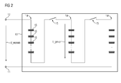
- FIG. 2 Another embodiment of an energy storage device according to the invention is shown in FIG. 2 played.
- the energy storage device is realized here as a module with a housing 10.
- the module has connection contacts 11, 12, between which a voltage U_module results.
- the module here consists of several series-connected cells 13 (power capacitors or battery blocks), which can be arranged in groups 14 of equal size so that the maximum voltage U_group is below the maximum low voltage at all times.
- circuit breakers 15 switching devices are mounted in such a way that a separation of the series connection of the cell groups 14 can be realized for service purposes.
- the circuit breaker 15 or switching devices can by means of a control device (In FIG. 2 not shown) are coupled to the module voltage U_module such that falls below a certain minimum voltage, the circuit breaker 15 automatically rise.
- the circuit breakers can also be controlled so that they automatically fall when the power supply to the control device (module electronics) falls. It is advisable to provide a delay time, so that in non-energized state, a drop in the power supply does not damage the circuit breaker 15 leads.
- the circuit breaker 15 also mechanically to a service lever (in FIG. 2 not shown), which is operated by the service personnel.
- a service lever in FIG. 2 not shown
- a separation of the series connection of the energy storage elements by operating a single lever, namely the service lever, a safe state of the energy storage device can be produced.
- a module residual discharge is thus not necessary and a safe touch voltage is ensured without significant delay. That For service purposes, for example, the energy storage module can be touched even when fully charged.
Landscapes
- Engineering & Computer Science (AREA)
- Transportation (AREA)
- Mechanical Engineering (AREA)
- Chemical & Material Sciences (AREA)
- Power Engineering (AREA)
- Sustainable Energy (AREA)
- Life Sciences & Earth Sciences (AREA)
- Sustainable Development (AREA)
- Chemical Kinetics & Catalysis (AREA)
- Electrochemistry (AREA)
- General Chemical & Material Sciences (AREA)
- Manufacturing & Machinery (AREA)
- Combustion & Propulsion (AREA)
- Microelectronics & Electronic Packaging (AREA)
- Electric Propulsion And Braking For Vehicles (AREA)
Priority Applications (1)
| Application Number | Priority Date | Filing Date | Title |
|---|---|---|---|
| EP11173272A EP2543534A1 (fr) | 2011-07-08 | 2011-07-08 | Dispositif de stockage d'énergie à sécurité améliorée, véhicule automobile comprennant un tel dispositiv et procédé de tenir en fonction un dispositif de stockage d'énergie |
Applications Claiming Priority (1)
| Application Number | Priority Date | Filing Date | Title |
|---|---|---|---|
| EP11173272A EP2543534A1 (fr) | 2011-07-08 | 2011-07-08 | Dispositif de stockage d'énergie à sécurité améliorée, véhicule automobile comprennant un tel dispositiv et procédé de tenir en fonction un dispositif de stockage d'énergie |
Publications (1)
| Publication Number | Publication Date |
|---|---|
| EP2543534A1 true EP2543534A1 (fr) | 2013-01-09 |
Family
ID=44583990
Family Applications (1)
| Application Number | Title | Priority Date | Filing Date |
|---|---|---|---|
| EP11173272A Withdrawn EP2543534A1 (fr) | 2011-07-08 | 2011-07-08 | Dispositif de stockage d'énergie à sécurité améliorée, véhicule automobile comprennant un tel dispositiv et procédé de tenir en fonction un dispositif de stockage d'énergie |
Country Status (1)
| Country | Link |
|---|---|
| EP (1) | EP2543534A1 (fr) |
Cited By (2)
| Publication number | Priority date | Publication date | Assignee | Title |
|---|---|---|---|---|
| CN110719856A (zh) * | 2017-04-07 | 2020-01-21 | 三星Sdi株式会社 | 用于驱动车辆的电源系统 |
| EP4320671A4 (fr) * | 2021-04-09 | 2025-07-09 | Brunswick Corp | Système et procédé de sécurité de batterie marine |
Citations (7)
| Publication number | Priority date | Publication date | Assignee | Title |
|---|---|---|---|---|
| EP0135056A1 (fr) * | 1983-07-25 | 1985-03-27 | Siemens Aktiengesellschaft | Agencement d'un système de stockage d'énergie électrochimique |
| US5773962A (en) * | 1995-01-17 | 1998-06-30 | Norvik Traction Inc. | Battery energy monitoring circuits |
| DE102008010971A1 (de) * | 2008-02-25 | 2009-08-27 | Robert Bosch Gmbh | Schutzsystem für Batteriemodule |
| US20100121511A1 (en) * | 2008-10-07 | 2010-05-13 | Boston-Power, Inc. | Li-ion battery array for vehicle and other large capacity applications |
| WO2010112694A2 (fr) * | 2009-04-02 | 2010-10-07 | Dow Kokam France Sas | Procede de securisation du fonctionnement d'une batterie electrique |
| WO2010138744A2 (fr) * | 2009-05-29 | 2010-12-02 | Ise Corporation | Stockage d'énergie électrique élevée dynamiquement reconfigurable pour véhicules hybrides |
| EP2355229A1 (fr) * | 2010-02-08 | 2011-08-10 | Fortu Intellectual Property AG | Système de batterie à courant élevé et procédé de commande d'un système de batterie à courant élevé |
-
2011
- 2011-07-08 EP EP11173272A patent/EP2543534A1/fr not_active Withdrawn
Patent Citations (7)
| Publication number | Priority date | Publication date | Assignee | Title |
|---|---|---|---|---|
| EP0135056A1 (fr) * | 1983-07-25 | 1985-03-27 | Siemens Aktiengesellschaft | Agencement d'un système de stockage d'énergie électrochimique |
| US5773962A (en) * | 1995-01-17 | 1998-06-30 | Norvik Traction Inc. | Battery energy monitoring circuits |
| DE102008010971A1 (de) * | 2008-02-25 | 2009-08-27 | Robert Bosch Gmbh | Schutzsystem für Batteriemodule |
| US20100121511A1 (en) * | 2008-10-07 | 2010-05-13 | Boston-Power, Inc. | Li-ion battery array for vehicle and other large capacity applications |
| WO2010112694A2 (fr) * | 2009-04-02 | 2010-10-07 | Dow Kokam France Sas | Procede de securisation du fonctionnement d'une batterie electrique |
| WO2010138744A2 (fr) * | 2009-05-29 | 2010-12-02 | Ise Corporation | Stockage d'énergie électrique élevée dynamiquement reconfigurable pour véhicules hybrides |
| EP2355229A1 (fr) * | 2010-02-08 | 2011-08-10 | Fortu Intellectual Property AG | Système de batterie à courant élevé et procédé de commande d'un système de batterie à courant élevé |
Cited By (5)
| Publication number | Priority date | Publication date | Assignee | Title |
|---|---|---|---|---|
| CN110719856A (zh) * | 2017-04-07 | 2020-01-21 | 三星Sdi株式会社 | 用于驱动车辆的电源系统 |
| EP3608153A4 (fr) * | 2017-04-07 | 2021-01-13 | Samsung SDI Co., Ltd. | Système d'alimentation électrique pour la conduite d'un véhicule |
| US11155172B2 (en) | 2017-04-07 | 2021-10-26 | Samsung Sdi Co., Ltd. | Power supply system for driving vehicle |
| CN110719856B (zh) * | 2017-04-07 | 2024-03-15 | 三星Sdi株式会社 | 用于驱动车辆的电源系统 |
| EP4320671A4 (fr) * | 2021-04-09 | 2025-07-09 | Brunswick Corp | Système et procédé de sécurité de batterie marine |
Similar Documents
| Publication | Publication Date | Title |
|---|---|---|
| EP3542437B1 (fr) | Procédé de sûreté, dispositif pour sa mise en oeuvre et véhicule hybride ou électrique | |
| DE102015204028B4 (de) | Hochspannungsunterbrechung für Elektrofahrzeuge | |
| DE102012204788B4 (de) | Steuerungsvorrichtung und Bordnetzsystem für ein elektromobiles Kraftfahrzeug mit einem Hochvolt-Bordnetz, bei dem die Überwachungsleitung als einer Teil einer Koaxialleitung realisiert ist, wobei ein anderer Teil der Koaxialleitung als Hochvolt-Leitung verwendet wird | |
| DE102016107707B3 (de) | Schutzvorrichtung für eine Hochvolt-Spannungsversorgung | |
| DE102016213072B4 (de) | Ein Hochvolt-Batteriesystem mit Sicherungseinrichtung | |
| DE102013017409A1 (de) | Batteriesystem mit einer Hochvolt-Batterie und einem Batterie-Management-System, insbesondere für ein elektromotorisch antreibbares Fahrzeug | |
| DE102019215517B3 (de) | Elektrisches Bordnetz sowie Verfahren zum Betrieb eines solchen Bordnetzes | |
| DE102012015523B4 (de) | Hochvoltbatterie mit Entlademöglichkeit nach einem Crash | |
| DE102018212405A1 (de) | Traktionsnetz und Verfahren zum Betreiben eines Traktionsnetzes eines elektrisch angetriebenen Fahrzeugs im Kurzschlussfall | |
| EP2777979A2 (fr) | Module de batterie électrique à sécurité intrinsèque avec circuit de décharge ultra-rapide et procédé de surveillance d'un module de batterie | |
| DE102018109824B3 (de) | Hochvoltschalter, Hochvoltbordnetz in einem Kraftfahrzeug und Verfahren zum Betreiben eines Hochvoltschalters | |
| DE102010029806A1 (de) | Elektrisches System | |
| DE102021201468B3 (de) | Architektur und Schaltungstopologie zur Sicherstellung einer schaltbaren allpoligen galvanischen Trennung in Hochvoltbatteriesystemen | |
| WO2014191135A1 (fr) | Séparation de modules dans des systèmes de batterie en cas d'accidents | |
| DE102021102049A1 (de) | Batterieanordnung, Kraftfahrzeug und Verfahren zum Betreiben einer Batterieanordnung | |
| DE102010045904A1 (de) | Energiespeichereinrichtung mit Kurzschlusssicherungsschaltung | |
| DE102018203915A1 (de) | HV-Energiespeicher | |
| DE102012213926A1 (de) | Batteriemodul, Batteriemanagementsystem, System zur Versorgung eines Antriebs einer zur Drehmomenterzeugung geeigneten Maschine mit elektrischer Energie und Kraftfahrzeug | |
| DE102010008203A1 (de) | Fahrzeug mit elektrischer Versorgungseinrichtung und Kollisionserkennung | |
| DE102016107706A1 (de) | Ansteuerungsvorrichtung für eine pyrotechnische Sicherungsvorrichtung | |
| DE102012214879A1 (de) | Verfahren und Vorrichtung für eine passive Aktivierung einer pyrotechnischen Sicherung im Batteriesystem | |
| DE102012221486A1 (de) | Vorrichtung zur Abtrennung einer Batterie von einem Stromkreis | |
| DE102021109345A1 (de) | Trennschaltung zur reversiblen galvanischen Trennung eines Verbrauchers von einer Gleichspannungsquelle | |
| EP3259787B1 (fr) | Procédé de fabrication d'une batterie | |
| WO2018108512A1 (fr) | Véhicule automobile avec un moteur électrique, notamment véhicule hybride ou électrique |
Legal Events
| Date | Code | Title | Description |
|---|---|---|---|
| PUAI | Public reference made under article 153(3) epc to a published international application that has entered the european phase |
Free format text: ORIGINAL CODE: 0009012 |
|
| AK | Designated contracting states |
Kind code of ref document: A1 Designated state(s): AL AT BE BG CH CY CZ DE DK EE ES FI FR GB GR HR HU IE IS IT LI LT LU LV MC MK MT NL NO PL PT RO RS SE SI SK SM TR |
|
| AX | Request for extension of the european patent |
Extension state: BA ME |
|
| RAP1 | Party data changed (applicant data changed or rights of an application transferred) |
Owner name: SIEMENS AKTIENGESELLSCHAFT |
|
| 17P | Request for examination filed |
Effective date: 20130705 |
|
| RBV | Designated contracting states (corrected) |
Designated state(s): AL AT BE BG CH CY CZ DE DK EE ES FI FR GB GR HR HU IE IS IT LI LT LU LV MC MK MT NL NO PL PT RO RS SE SI SK SM TR |
|
| STAA | Information on the status of an ep patent application or granted ep patent |
Free format text: STATUS: THE APPLICATION IS DEEMED TO BE WITHDRAWN |
|
| 18D | Application deemed to be withdrawn |
Effective date: 20150203 |