EP2543782A2 - Dispositif d'actionnement d'un clapet de sortie sanitaire, en particulier clapet de chasse d'eau ou baignoire - Google Patents
Dispositif d'actionnement d'un clapet de sortie sanitaire, en particulier clapet de chasse d'eau ou baignoire Download PDFInfo
- Publication number
- EP2543782A2 EP2543782A2 EP12167616A EP12167616A EP2543782A2 EP 2543782 A2 EP2543782 A2 EP 2543782A2 EP 12167616 A EP12167616 A EP 12167616A EP 12167616 A EP12167616 A EP 12167616A EP 2543782 A2 EP2543782 A2 EP 2543782A2
- Authority
- EP
- European Patent Office
- Prior art keywords
- drain valve
- bowden cable
- housing
- coupled
- coupling element
- Prior art date
- Legal status (The legal status is an assumption and is not a legal conclusion. Google has not performed a legal analysis and makes no representation as to the accuracy of the status listed.)
- Granted
Links
- 238000011010 flushing procedure Methods 0.000 title description 10
- 230000008878 coupling Effects 0.000 claims abstract description 34
- 238000010168 coupling process Methods 0.000 claims abstract description 34
- 238000005859 coupling reaction Methods 0.000 claims abstract description 34
- XLYOFNOQVPJJNP-UHFFFAOYSA-N water Substances O XLYOFNOQVPJJNP-UHFFFAOYSA-N 0.000 description 12
- 238000007789 sealing Methods 0.000 description 7
- 238000004519 manufacturing process Methods 0.000 description 4
- 210000002445 nipple Anatomy 0.000 description 4
- 238000007689 inspection Methods 0.000 description 2
- 238000009434 installation Methods 0.000 description 2
- 239000000463 material Substances 0.000 description 2
- 230000009977 dual effect Effects 0.000 description 1
- 230000000694 effects Effects 0.000 description 1
- 230000002349 favourable effect Effects 0.000 description 1
- 230000000977 initiatory effect Effects 0.000 description 1
- 238000000034 method Methods 0.000 description 1
- 230000000149 penetrating effect Effects 0.000 description 1
- 230000001960 triggered effect Effects 0.000 description 1
Images


Classifications
-
- E—FIXED CONSTRUCTIONS
- E03—WATER SUPPLY; SEWERAGE
- E03D—WATER-CLOSETS OR URINALS WITH FLUSHING DEVICES; FLUSHING VALVES THEREFOR
- E03D5/00—Special constructions of flushing devices, e.g. closed flushing system
- E03D5/02—Special constructions of flushing devices, e.g. closed flushing system operated mechanically or hydraulically (or pneumatically) also details such as push buttons, levers and pull-card therefor
- E03D5/09—Special constructions of flushing devices, e.g. closed flushing system operated mechanically or hydraulically (or pneumatically) also details such as push buttons, levers and pull-card therefor directly by the hand
- E03D5/094—Special constructions of flushing devices, e.g. closed flushing system operated mechanically or hydraulically (or pneumatically) also details such as push buttons, levers and pull-card therefor directly by the hand the flushing element, e.g. siphon bell, being actuated through a cable, chain or the like
-
- E—FIXED CONSTRUCTIONS
- E03—WATER SUPPLY; SEWERAGE
- E03C—DOMESTIC PLUMBING INSTALLATIONS FOR FRESH WATER OR WASTE WATER; SINKS
- E03C1/00—Domestic plumbing installations for fresh water or waste water; Sinks
- E03C1/12—Plumbing installations for waste water; Basins or fountains connected thereto; Sinks
- E03C1/22—Outlet devices mounted in basins, baths, or sinks
- E03C1/23—Outlet devices mounted in basins, baths, or sinks with mechanical closure mechanisms
- E03C1/2304—Outlet devices mounted in basins, baths, or sinks with mechanical closure mechanisms the actuation force being transmitted to the plug via flexible elements, e.g. chain, Bowden cable
-
- E—FIXED CONSTRUCTIONS
- E03—WATER SUPPLY; SEWERAGE
- E03D—WATER-CLOSETS OR URINALS WITH FLUSHING DEVICES; FLUSHING VALVES THEREFOR
- E03D5/00—Special constructions of flushing devices, e.g. closed flushing system
- E03D5/10—Special constructions of flushing devices, e.g. closed flushing system operated electrically, e.g. by a photo-cell; also combined with devices for opening or closing shutters in the bowl outlet and/or with devices for raising/or lowering seat and cover and/or for swiveling the bowl
-
- F—MECHANICAL ENGINEERING; LIGHTING; HEATING; WEAPONS; BLASTING
- F16—ENGINEERING ELEMENTS AND UNITS; GENERAL MEASURES FOR PRODUCING AND MAINTAINING EFFECTIVE FUNCTIONING OF MACHINES OR INSTALLATIONS; THERMAL INSULATION IN GENERAL
- F16K—VALVES; TAPS; COCKS; ACTUATING-FLOATS; DEVICES FOR VENTING OR AERATING
- F16K31/00—Actuating devices; Operating means; Releasing devices
- F16K31/02—Actuating devices; Operating means; Releasing devices electric; magnetic
- F16K31/04—Actuating devices; Operating means; Releasing devices electric; magnetic using a motor
- F16K31/05—Actuating devices; Operating means; Releasing devices electric; magnetic using a motor specially adapted for operating hand-operated valves or for combined motor and hand operation
-
- F—MECHANICAL ENGINEERING; LIGHTING; HEATING; WEAPONS; BLASTING
- F16—ENGINEERING ELEMENTS AND UNITS; GENERAL MEASURES FOR PRODUCING AND MAINTAINING EFFECTIVE FUNCTIONING OF MACHINES OR INSTALLATIONS; THERMAL INSULATION IN GENERAL
- F16K—VALVES; TAPS; COCKS; ACTUATING-FLOATS; DEVICES FOR VENTING OR AERATING
- F16K31/00—Actuating devices; Operating means; Releasing devices
- F16K31/44—Mechanical actuating means
- F16K31/46—Mechanical actuating means for remote operation
- F16K31/465—Mechanical actuating means for remote operation by flexible transmission means, e.g. cable, chain, bowden wire
Definitions
- the invention relates to a device for actuating a sanitary drain valve, in particular Spippokasten-drain valve or bathtub drain valve, with at least one electric motor drive and at least a first manual actuator having manual release device, wherein the electric motor drive via at least one first Bowden cable actuates the drain valve and the at least one first manual actuating element is provided with at least one second Bowden cable for actuating the drain valve.
- Such a device is for example from the DE 20 2007 003 163 U1 known.
- actuating plates for triggering a toilet or urinal flushing work purely mechanically. They usually have one or two operation keys that are movable, usually pivotally mounted in the actuator plate. Furthermore, devices for triggering a toilet or urinal flush are known, which have an electromagnetic or electric motor drive.
- the DE 20 2007 003 163 U1 discloses a device for the electrical triggering of a flushing process in a sanitary cistern, comprising a drain valve arranged in the flush valve, an electronic control and at least one connected to the electronic control push button for actuating the drain valve.
- the drain valve is associated with an electric linear drive, which is actuated by the electronic control when touching the at least one tactile sensor and actuates the drain valve via a Bowden cable.
- the drain valve is additionally provided with a purely mechanically running triggering device.
- This mechanical release device has a manual actuator, such as a push button, wherein the manual actuator is connected to another Bowden cable for actuating the drain valve.
- Sanitary cisterns are nowadays usually designed in dual-mode, i. They allow the initiation of a full flush with a relatively large amount of flushing water and alternatively - for cases in which a lower amount of flushing sufficient - the release of a partial flush with a relatively small amount of flushing water.
- the present invention therefore an object of the invention to further develop a device of the type mentioned in that the drain valve can be operated both manually and on demand manually, purely mechanically with small and large amount of flushing water.
- the device according to the invention is characterized in that the at least one first Bowden cable, which is assigned to the electromotive drive, is coupled to at least one first driver, and the at least one second Bowden cable, which is assigned to the at least one first manual actuating element, with at least one second Driver is coupled, wherein the drivers are movable relative to each other, and wherein the respective driver in a transmitted to him via the Bowden cable coupled with it movement carries a coupling element to which at least a third Bowden cable is coupled, coupled to actuate the drain valve with the same is.
- the device according to the invention thus has a Multitu Kunststofffactponente for Bowden cables, which makes it possible to trigger a full flush and optionally a partial flush each with purely mechanically functioning actuation systems and a full or partial flush with an electric motor drive with a suitable dual rate drain valve.
- the multi-component of the device according to the invention can also be referred to as Bowdenzugweiche.
- the Bowden Dodge allows the implementation of more than two actuation variants.
- Several independently operable Bowden cables are coupled to a common Bowden cable for triggering a drain valve or for actuating a trigger lever of the drain valve. Consequently, a plurality of actuation variants can be combined with one another using the device according to the invention.
- the manual release device of the device according to the invention on at least a second manual actuator, which is provided with at least a fourth Bowden cable, which is coupled to actuate the drain valve with the same.
- the second manual actuator and the at least one fourth Bowden cable serve to trigger a partial flush, whereas the first manual actuator and associated therewith at least one Bowden cable are associated with triggering a full flush.
- a further preferred embodiment of the device according to the invention is characterized in that the driver and the coupling element are mounted in a housing movable, preferably displaceable, wherein the housing has a cup-shaped housing part and a removable or hinged lid.
- the housing offers next to a simple mountability and reliable movable mounting of the driver and the coupling element and a safe protection of these components from external mechanical effects.
- the lid and the shell-shaped housing part have mutually associated latching elements.
- the locking elements allow a particularly simple and quick connection of said housing parts and thus a simple and fast closing of the housing.
- a further advantageous embodiment of the device according to the invention provides that the housing has grooves, slots and / or ribs for guiding the coupling element and / or the driver.
- the said guide means are integrated in the housing. The production and assembly of further separate guide elements is thus not required, so that unnecessary material and manufacturing costs can be avoided.
- a further advantageous embodiment of the device according to the invention provides that in the wall of the housing openings or recesses are formed, on which sleeves are fixed positively for receiving one end of the tubular jacket of the first, second and third Bowden cable. This embodiment enables a simple and reliable connection of said Bowden cables to the housing.
- the coupling element and / or the driver are biased with at least one spring element in an initial position.
- This embodiment simplifies the manual operation of the sanitary drain valve.
- a provided for manual operation of the drain valve control element, such as a push button is moved back to the manual operation of the drain valve in an initial position, wherein the coupling element and / or the driver acting spring element Supported movement of the control element to its starting position.
- the coupling element is provided with a plate-shaped element which has grooves, slots and / or ribs for guiding the driver.
- the respective driver preferably has a projection engaging an edge of the plate-shaped element of the coupling element.
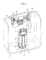
- Fig. 1 shows a portion of a concealed cistern 1.
- the cistern 1 has a drain valve 2, which is mounted on a bottom opening of the Spülkasten emotionss.
- the raisable and lowerable valve body 3 of the drain valve 2 is formed as an overflow pipe, at the lower end of a flange-shaped sealing ring 4 is attached.
- the sealing ring 4 is located in the closed drain valve 2 on a valve seat, which is formed at the top of the Spülkastenêt 6 penetrating pipe socket. If there is a certain amount of water in the cistern 1, the water column pushes the sealing ring 4 against the annular valve seat.
- an annular flange 7 is integrally formed, which rests watertight on a Spülringêt 6 via a sealing ring (not shown).
- the drain valve 2 has a housing 8, which is connected via web-shaped support elements 9 with the flange 7.
- the formed as an overflow valve body 3 is provided with a float (not shown), which is guided in the housing 8.
- the drain valve 2 is provided with a pivotally mounted lever (not shown), which causes a lifting of the valve body 3 during a pivoting movement and is connected to a Bowden cable 10.
- the lever is mounted in a holder 11 which is detachably connected to the housing 8 of the drain valve 2.
- a projection (not shown) is formed, which engages under the lever.
- the lever can pivot upward, so that the lever detects the projection of the valve body 3 and raises it against the pressure on the sealing ring 4 on the sealing ring. In this case, a slight lifting of the sealing ring 4 from the valve seat is sufficient.
- the further lifting of the valve body 3 is effected in cistern 1 filled with water by the float attached to the valve body 3.
- the drive (motor) 12 can also be referred to as a linear motor or a translationally acting actuator. With 13, an electrical connection for the engine 12 is designated.
- the electric motor drive 12 is mounted on a mounting frame 14, which is prepared for mounting on an inspection opening 15 of the cistern 1.
- an electronic control is provided, to which at least one key switch or push button sensor (not shown) is connected for actuating the drain valve 2.
- at least two key switches are connected to the electronic control, wherein a key switch is used to trigger a full flush with a defined amount of water and a second key switch is used to trigger a partial flush with a smaller defined amount of water.
- the in Fig. 1 illustrated cistern 1 also offers the possibility of an independent of the electric motor drive manual operation (triggering) of the drain valve 2.
- the drain valve 2 is additionally provided with a purely mechanical triggering device.
- the mechanical release device on a manual actuator which is connected to a further Bowden cable 16 for actuating the drain valve 2.
- the manual actuator (in Fig. 1 not shown) is formed, for example, as a push button, handle or pull knob and preferably arranged at a hidden location on the outside of the inspection opening 15 covering cover plate or at another location on the outside of the cistern 1-containing wall and accessible to the user if necessary.
- a further lever (not shown) is used, which is also pivotally mounted in the holder 11 and causes a lifting movement of the valve body 3 of the drain valve 2 in a pivoting movement.
- a device according to the invention which makes it possible to operate a lever or other adjusting element on the drain valve 2 for lifting or moving the valve body 3 optionally with an electric motor drive 12 or (independently of the drive 12) with a manual actuator 17.
- a lever or other adjusting element on the drain valve 2 for lifting or moving the valve body 3 optionally with an electric motor drive 12 or (independently of the drive 12) with a manual actuator 17.
- 11 is one with a cistern drain valve 2 according to Fig. 1 detachably connectable holder called. On the holder 11 at least two levers or adjusting elements for lifting the valve body 3 of the drain valve 2 are movably mounted.
- the first lever or the first control element 11.1 is used to trigger a full flush, in which an amount of water in the range of, for example, 6 to 9 liters is passed through a connected to the cistern 1 flushing pipe in a connected toilet bowl, whereas the second control element 11.2 and second lever on the holder 11 of the triggering of a partial flush is used, in which an amount of water, for example, about 3 liters from the cistern 1 is passed into the connected toilet bowl.
- the manual actuators 17, 19 each have a pivotally mounted lever 20. They can also be called force transducers. Because they turn one on the Lever 20 applied compressive force in a force acting on the connected Bowden cable 16 and 21 traction.
- the device according to the invention has a Bowden dipper 22.
- the Bowdenzugweiche 22 includes a movably mounted coupling element 23 to which the Bowden cable 18 connected to the holder 11 is coupled. Further, the Bowdenzugweiche 22 (at least) two drivers 24, 25 which are movable relative to each other and independently, at least a first driver 24 which is coupled to at least a first, the engine 12 associated Bowden cable 26, and at least one second Driver 25, which is coupled to at least a second, the manual actuator 17 associated Bowden cable 21.
- the drivers 24, 25 and the coupling element 23 are slidably mounted in a housing 27.
- the housing 27 has a cup-shaped housing part 27.1 and a housing cover 27.2.
- the cover 27.2 is connected via a hinge 27.3, preferably hinged hinged to the cup-shaped housing part 27.1.
- the cover 27.2 and the housing part 27.1 have mutually associated latching elements.
- the locking elements are formed from resilient latching lugs 28 and their associated recesses 29.
- the recesses 29 are formed on the hinge 27.3 opposite longitudinal side of the housing part 27.1.
- the locking lugs 28 are accordingly formed on the hinge 27.3 opposite longitudinal side of the lid 27.2 on the same.
- the housing 27, namely the cup-shaped housing part 27.1 has elongated, substantially rectilinear ribs 27.4 for guiding the coupling element 23 and / or the drivers 24, 25.
- the ribs 27.4 are formed on the housing bottom inside.
- the ribs 27.4 also substantially rectilinear grooves and / or slots for guiding the coupling element 23 and / or the driver 24, 25 may be formed in the housing 27.
- the coupling element 23 has grooves into which the projections or ribs 27.4 of the housing bottom engage with play.
- the coupling element 23 comprises a plate-shaped element 23.1, which has a slotted receiving eye 23.2 for suspending a nipple firmly connected to the end of the wire core 18.1 of the Bowden cable 18 in the region of its longitudinal central axis. Furthermore, the coupling element 23 is provided with a spring element 30, by means of which it is biased into an initial position.
- the spring element 30 preferably consists of a helical spring. One end of the coil spring 30 is mounted on a arranged on the inside of the housing 27, preferably molded pin 27.5. The other end of the coil spring 30 is inserted into a sleeve-shaped receptacle 23.3, which is connected to the coupling element 23.
- the sleeve-shaped receptacle 23.3 is the slotted receiving eye 23.2 opposite.
- the longitudinal center axis of the pin 27.5 and the coil spring 30 and the longitudinal center axis of the sleeve-shaped receptacle 23.3 are aligned with each other.
- the end portion of the wire core 18.1 of the Bowden cable 18 is aligned with the Longitudinal axis of the pin 27.5 or with the longitudinal center axis of the sleeve-shaped coil spring receptacle 23.3.
- slots 23.6 and / or ribs for guiding the drivers 24, 25 are further formed.
- the respective driver 24, 25 is formed substantially in the form of an elongated cuboid or rod. He has at one of its ends a slotted receiving eyelet 24.1 and 25.1 for hanging a firmly connected to the end of the wire core 21.1 and 26.1 of the Bowden cable 21, 26 nipple. At its other end, the driver 24, 25 has an engaging on an edge of the plate-shaped part 23.1 of the coupling element 23 projection 24.2, 25.2.
- the receiving lug 24.1, 25.1 of the driver 24, 25 is arranged away from the receiving lug 23.2 of the coupling element 23, or in other words, the projection 24.2, 25.2 of the driver 24, 25 engages the edge of the plate-shaped part 23.1 of the coupling piece 23 at which is the receiving eye 23.2.
- FIGS. 2 to 8 recognize that 27 openings 27.6 are formed in the wall of the housing, which serve to introduce ends of the Bowden cables 18, 21, 26 in the housing interior.
- the openings 27.6 are provided in the cup-shaped housing part 27.1 and open at the dividing plane defined by the housing part 27.1 and the housing cover 27.2.
- sleeves 31 are fixed positively, wherein the respective sleeve 31 receives one end of the tubular Bowden cable sheath (Bowden cable sheath).
- the wire core of the Bowden cable 18, 21, 26 terminates in the interior of the housing 27.
- these sleeves 31st have two spaced-apart annular projections 31.1 or have on their lateral surface an annular groove 31.2.
- projections 27.7 are formed with trough-shaped depressions, which are associated with the openings 27.6 in the wall of the cup-shaped housing part 27.2.
- the projections 27.7 engage in the closed position of the cover 27.2 in the annular groove 31.2 of the Bowdenzughülsen 30, so that an additional positive fixing of the sleeves 31 results in the housing 27.
- FIGS. 3 and 4 show the coupling element 23 and the drivers 24, 25 in their initial position (zero position).
- the drivers 24, 25 are in this position next to each other and substantially at the same height.
- the coil spring 30 is not or only slightly compressed in the starting position.
- FIGS. 5 and 6 a position of the Bowden cable switch 22 effected by actuation of the Bowden cable 26 associated with the motor 12 is shown.
- the motor 12 associated driver 24 was used with the Bowden cable 26 closer to the sleeve 31.
- the coil spring 30 is strongly compressed in this position.
- the projecting in the direction of the housing bottom projection 24.2 of the driver 24 abuts the edge of the plate-shaped part 23.1 of the coupling element 23 and has the coupling element 23 taken in the direction of the fixed housing 27 in the sleeve 31 of the Bowden cable 26.
- the other driver 25 which is associated with the Bowden cable 21 and the manual actuator 17 is in its initial position (zero position) according to the FIGS. 3 and 4 remained.
- FIGS. 7 and 8 finally, a position of the Bowdenzugweiche 22 effected by actuation of the manual actuating element 17 associated Bowden cable 21 is shown.
- the manual actuator 17 associated driver 25 was used by means of the Bowden cable 21 closer to the sleeve 31.
- the coil spring 30 is in turn strongly compressed.
- the protruding in the direction of the housing bottom projection 25.2 of the driver 25 abuts the edge of the plate-shaped part 23.1 of the coupling element 23 and has the coupling element 23 taken in the direction of the fixed housing 27 in the sleeve 31 of the Bowden cable 21.
- the driver 12 associated with the driver 24, however, is in its initial position (zero position) according to the FIGS. 3 and 4 remained.
- the Bowdenzugweiche 22 can be variably arranged within a cistern 1 due to the flexibility of the Bowden cables 18, 21, 26.
- the length of the Bowden cables 18, 21, 26 can be adjusted as needed, wherein the housing 27 of the Bowdenzugweiche 22 each by the coupled with the coupling piece 23 (third) Bowden cable 18 can be arranged at a distance from the drain valve 2.
- the attached at the ends of the Bowden cable cores nipples are fixed to the respective wire core or detachably connected as a clamping nipple.
- the motor 12 is provided with a flexible power supply or control cable 13.
- the embodiment of the present invention is not limited to the embodiment described above and shown in the drawing. Rather, numerous variants are possible, even with deviating design of the invention specified in the accompanying claims Make use.
- the device according to the invention can not be used only in a sanitary cistern 1.
- a use in other sanitary drain valves, such as a bathtub drain valve is possible.
- the Bowden cables 16 and 18 without a releasable support 11 according to Fig. 2 be mounted directly on the housing of a drain valve 2.
- the use of a detachable holder 11 according to Fig. 2 However, in particular with regard to a pre-assembly of the Bowden cables 16, 18, the manual actuators 17, 19 and the electric motor drive 12 advantageous and therefore preferred.
Landscapes
- Engineering & Computer Science (AREA)
- General Engineering & Computer Science (AREA)
- Mechanical Engineering (AREA)
- Water Supply & Treatment (AREA)
- Health & Medical Sciences (AREA)
- Life Sciences & Earth Sciences (AREA)
- Hydrology & Water Resources (AREA)
- Public Health (AREA)
- Aviation & Aerospace Engineering (AREA)
- Environmental & Geological Engineering (AREA)
- Mechanically-Actuated Valves (AREA)
- Sink And Installation For Waste Water (AREA)
- Electrically Driven Valve-Operating Means (AREA)
Priority Applications (1)
| Application Number | Priority Date | Filing Date | Title |
|---|---|---|---|
| PL12167616T PL2543782T3 (pl) | 2011-07-07 | 2012-05-11 | Urządzenie do uruchamiania sanitarnego zaworu spustowego, w szczególności zaworu spustowego spłuczki lub wanny kąpielowej |
Applications Claiming Priority (1)
| Application Number | Priority Date | Filing Date | Title |
|---|---|---|---|
| DE202011103214U DE202011103214U1 (de) | 2011-07-07 | 2011-07-07 | Vorrichtung zur Betätigung eines sanitären Ablaufventils, insbesondere Spülkasten- oder Badewannen-Ablaufventils |
Publications (3)
| Publication Number | Publication Date |
|---|---|
| EP2543782A2 true EP2543782A2 (fr) | 2013-01-09 |
| EP2543782A3 EP2543782A3 (fr) | 2014-12-24 |
| EP2543782B1 EP2543782B1 (fr) | 2016-01-06 |
Family
ID=46317133
Family Applications (1)
| Application Number | Title | Priority Date | Filing Date |
|---|---|---|---|
| EP12167616.7A Active EP2543782B1 (fr) | 2011-07-07 | 2012-05-11 | Dispositif d'actionnement d'un clapet de sortie sanitaire, en particulier clapet de chasse d'eau ou baignoire |
Country Status (4)
| Country | Link |
|---|---|
| EP (1) | EP2543782B1 (fr) |
| DE (1) | DE202011103214U1 (fr) |
| ES (1) | ES2565495T3 (fr) |
| PL (1) | PL2543782T3 (fr) |
Cited By (3)
| Publication number | Priority date | Publication date | Assignee | Title |
|---|---|---|---|---|
| US10907332B2 (en) | 2017-09-01 | 2021-02-02 | Kohler Co. | Flush actuator assembly |
| IT202100003224A1 (it) * | 2021-02-12 | 2022-08-12 | Oli Sist Sanitarios S A | Gruppo placca di comando per una cassetta di risciacquo |
| WO2025190445A1 (fr) | 2024-03-14 | 2025-09-18 | Blanco Gmbh + Co Kg | Dispositif d'actionnement pour ouvrir et fermer une vanne d'un ensemble de vidange |
Families Citing this family (2)
| Publication number | Priority date | Publication date | Assignee | Title |
|---|---|---|---|---|
| DE202014104522U1 (de) * | 2014-09-22 | 2016-01-04 | Viega Gmbh & Co. Kg | Ablaufgarnitur für eine Spüle, insbesondere Küchenspüle |
| CN107143014B (zh) * | 2017-06-07 | 2023-02-10 | 厦门瑞尔特卫浴科技股份有限公司 | 一种双排扳钮结构 |
Citations (1)
| Publication number | Priority date | Publication date | Assignee | Title |
|---|---|---|---|---|
| DE202007003163U1 (de) | 2007-03-01 | 2008-07-17 | Viega Gmbh & Co. Kg | Vorrichtung zur elektrischen Auslösung eines Spülvorgangs in einem sanitären Spülkasten |
Family Cites Families (3)
| Publication number | Priority date | Publication date | Assignee | Title |
|---|---|---|---|---|
| DE19816991C2 (de) * | 1998-04-17 | 2000-11-02 | Daimler Chrysler Ag | Betätigungssystem für Fahrzeuge |
| DE102005037122A1 (de) * | 2005-08-06 | 2007-02-08 | Abertax Research And Development Ltd. | Flüssigkeitsbehälter mit Organen für den Zulauf und/oder den Ablauf der Flüssigkeit |
| DE102007052771B4 (de) * | 2007-11-02 | 2020-01-02 | Magna BÖCO GmbH | Vorrichtung zur Verbindung von wenigstens zwei Seilzügen miteinander |
-
2011
- 2011-07-07 DE DE202011103214U patent/DE202011103214U1/de not_active Expired - Lifetime
-
2012
- 2012-05-11 PL PL12167616T patent/PL2543782T3/pl unknown
- 2012-05-11 ES ES12167616.7T patent/ES2565495T3/es active Active
- 2012-05-11 EP EP12167616.7A patent/EP2543782B1/fr active Active
Patent Citations (1)
| Publication number | Priority date | Publication date | Assignee | Title |
|---|---|---|---|---|
| DE202007003163U1 (de) | 2007-03-01 | 2008-07-17 | Viega Gmbh & Co. Kg | Vorrichtung zur elektrischen Auslösung eines Spülvorgangs in einem sanitären Spülkasten |
Cited By (4)
| Publication number | Priority date | Publication date | Assignee | Title |
|---|---|---|---|---|
| US10907332B2 (en) | 2017-09-01 | 2021-02-02 | Kohler Co. | Flush actuator assembly |
| IT202100003224A1 (it) * | 2021-02-12 | 2022-08-12 | Oli Sist Sanitarios S A | Gruppo placca di comando per una cassetta di risciacquo |
| EP4043653A1 (fr) * | 2021-02-12 | 2022-08-17 | Oli - Sistemas Sanitarios, S.A. | Ensemble plaque de commande pour un réservoir de chasse d'eau |
| WO2025190445A1 (fr) | 2024-03-14 | 2025-09-18 | Blanco Gmbh + Co Kg | Dispositif d'actionnement pour ouvrir et fermer une vanne d'un ensemble de vidange |
Also Published As
| Publication number | Publication date |
|---|---|
| PL2543782T3 (pl) | 2016-06-30 |
| EP2543782A3 (fr) | 2014-12-24 |
| EP2543782B1 (fr) | 2016-01-06 |
| DE202011103214U1 (de) | 2012-10-12 |
| ES2565495T3 (es) | 2016-04-05 |
Similar Documents
| Publication | Publication Date | Title |
|---|---|---|
| EP3423655B1 (fr) | Dispositif pour ouvrir une porte ou un ouvrant sur un véhicule automobile | |
| EP2543782B1 (fr) | Dispositif d'actionnement d'un clapet de sortie sanitaire, en particulier clapet de chasse d'eau ou baignoire | |
| DE102018123949A1 (de) | Betätigungsvorrichtung | |
| EP1895067B1 (fr) | Dispositif destiné à l'actionnement d'une chasse d'eau de WC réalisé dans une technique de rinçage à deux quantités | |
| EP1964988B1 (fr) | Dispositif de chasse d'eau électromécanique | |
| DE3132270A1 (de) | Motorbetaetigte antennenanlage | |
| DE102016006751A1 (de) | Betätigungseinheit für ein Schaltgetriebe eines schaltbaren Antriebsstranges | |
| DE102013201322B4 (de) | Sanitärarmatur mit tastenbetätigbarem Steuerorgan | |
| EP1916343B1 (fr) | Robinet de chasse à action double | |
| EP2369071A1 (fr) | Agencement de transmission de force pour un dispositif d'actionnement et dispositif d'actionnement | |
| EP1316131A1 (fr) | Dispositif de fermeture d'un disjoncteur enfichable | |
| EP2388379B1 (fr) | Dispositif d'actionnement pour une chasse d'eau | |
| EP1794377B1 (fr) | Armature sanitaire encastree | |
| DE102016121199A1 (de) | Schließeinrichtung für ein Kraftfahrzeug | |
| DE102019128296A1 (de) | Kraftfahrzeugschlossanordnung | |
| EP2331783A1 (fr) | Boîtier pour la réception au moins partielle d'une ferrure de meuble | |
| DE10359246B4 (de) | Handbremshebelvorrichtung eines Fahrzeuges | |
| DE202006016049U1 (de) | Betätigungsvorrichtung für ein Ablaufventil eines sanitären Spülkastens | |
| EP2775048B1 (fr) | Kit comprenant une base et une pluralité de modules d'actionnement | |
| CH682837A5 (de) | Bowdenzug für Ventilbetätigung an einem Sanitär-Ablaufventil und Verfahren zu seiner Herstellung. | |
| EP1438777A2 (fr) | Cadre porteur pour commutateur electrique | |
| EP1612338A1 (fr) | Dispositif de levage pour l'appareil sanitaire | |
| EP1088942A2 (fr) | Dispositif d'actionnement | |
| DE102005011984B4 (de) | Elektrisch betriebene Standardarmatur mit getrennt angeordneten Funktionseinheiten | |
| DE102020118728A1 (de) | Aufstellvorrichtung für ein Kraftfahrzeugtürelement |
Legal Events
| Date | Code | Title | Description |
|---|---|---|---|
| PUAI | Public reference made under article 153(3) epc to a published international application that has entered the european phase |
Free format text: ORIGINAL CODE: 0009012 |
|
| AK | Designated contracting states |
Kind code of ref document: A2 Designated state(s): AL AT BE BG CH CY CZ DE DK EE ES FI FR GB GR HR HU IE IS IT LI LT LU LV MC MK MT NL NO PL PT RO RS SE SI SK SM TR |
|
| AX | Request for extension of the european patent |
Extension state: BA ME |
|
| PUAL | Search report despatched |
Free format text: ORIGINAL CODE: 0009013 |
|
| AK | Designated contracting states |
Kind code of ref document: A3 Designated state(s): AL AT BE BG CH CY CZ DE DK EE ES FI FR GB GR HR HU IE IS IT LI LT LU LV MC MK MT NL NO PL PT RO RS SE SI SK SM TR |
|
| AX | Request for extension of the european patent |
Extension state: BA ME |
|
| RIC1 | Information provided on ipc code assigned before grant |
Ipc: E03D 5/10 20060101ALI20141117BHEP Ipc: F16K 31/05 20060101ALI20141117BHEP Ipc: E03D 5/094 20060101AFI20141117BHEP Ipc: E03C 1/23 20060101ALI20141117BHEP |
|
| 17P | Request for examination filed |
Effective date: 20150224 |
|
| RBV | Designated contracting states (corrected) |
Designated state(s): AL AT BE BG CH CY CZ DE DK EE ES FI FR GB GR HR HU IE IS IT LI LT LU LV MC MK MT NL NO PL PT RO RS SE SI SK SM TR |
|
| GRAP | Despatch of communication of intention to grant a patent |
Free format text: ORIGINAL CODE: EPIDOSNIGR1 |
|
| INTG | Intention to grant announced |
Effective date: 20150710 |
|
| GRAS | Grant fee paid |
Free format text: ORIGINAL CODE: EPIDOSNIGR3 |
|
| GRAA | (expected) grant |
Free format text: ORIGINAL CODE: 0009210 |
|
| RAP1 | Party data changed (applicant data changed or rights of an application transferred) |
Owner name: VIEGA GMBH & CO. KG |
|
| AK | Designated contracting states |
Kind code of ref document: B1 Designated state(s): AL AT BE BG CH CY CZ DE DK EE ES FI FR GB GR HR HU IE IS IT LI LT LU LV MC MK MT NL NO PL PT RO RS SE SI SK SM TR |
|
| REG | Reference to a national code |
Ref country code: GB Ref legal event code: FG4D Free format text: NOT ENGLISH |
|
| REG | Reference to a national code |
Ref country code: CH Ref legal event code: EP |
|
| REG | Reference to a national code |
Ref country code: IE Ref legal event code: FG4D Free format text: LANGUAGE OF EP DOCUMENT: GERMAN |
|
| REG | Reference to a national code |
Ref country code: AT Ref legal event code: REF Ref document number: 768990 Country of ref document: AT Kind code of ref document: T Effective date: 20160215 |
|
| REG | Reference to a national code |
Ref country code: DE Ref legal event code: R096 Ref document number: 502012005643 Country of ref document: DE |
|
| REG | Reference to a national code |
Ref country code: CH Ref legal event code: NV Representative=s name: SCHMAUDER AND PARTNER AG PATENT- UND MARKENANW, CH |
|
| REG | Reference to a national code |
Ref country code: ES Ref legal event code: FG2A Ref document number: 2565495 Country of ref document: ES Kind code of ref document: T3 Effective date: 20160405 |
|
| REG | Reference to a national code |
Ref country code: NL Ref legal event code: FP |
|
| REG | Reference to a national code |
Ref country code: LT Ref legal event code: MG4D |
|
| REG | Reference to a national code |
Ref country code: FR Ref legal event code: PLFP Year of fee payment: 5 |
|
| PG25 | Lapsed in a contracting state [announced via postgrant information from national office to epo] |
Ref country code: HR Free format text: LAPSE BECAUSE OF FAILURE TO SUBMIT A TRANSLATION OF THE DESCRIPTION OR TO PAY THE FEE WITHIN THE PRESCRIBED TIME-LIMIT Effective date: 20160106 Ref country code: FI Free format text: LAPSE BECAUSE OF FAILURE TO SUBMIT A TRANSLATION OF THE DESCRIPTION OR TO PAY THE FEE WITHIN THE PRESCRIBED TIME-LIMIT Effective date: 20160106 Ref country code: GR Free format text: LAPSE BECAUSE OF FAILURE TO SUBMIT A TRANSLATION OF THE DESCRIPTION OR TO PAY THE FEE WITHIN THE PRESCRIBED TIME-LIMIT Effective date: 20160407 Ref country code: NO Free format text: LAPSE BECAUSE OF FAILURE TO SUBMIT A TRANSLATION OF THE DESCRIPTION OR TO PAY THE FEE WITHIN THE PRESCRIBED TIME-LIMIT Effective date: 20160406 |
|
| PG25 | Lapsed in a contracting state [announced via postgrant information from national office to epo] |
Ref country code: SE Free format text: LAPSE BECAUSE OF FAILURE TO SUBMIT A TRANSLATION OF THE DESCRIPTION OR TO PAY THE FEE WITHIN THE PRESCRIBED TIME-LIMIT Effective date: 20160106 Ref country code: LT Free format text: LAPSE BECAUSE OF FAILURE TO SUBMIT A TRANSLATION OF THE DESCRIPTION OR TO PAY THE FEE WITHIN THE PRESCRIBED TIME-LIMIT Effective date: 20160106 Ref country code: BE Free format text: LAPSE BECAUSE OF NON-PAYMENT OF DUE FEES Effective date: 20160531 Ref country code: LV Free format text: LAPSE BECAUSE OF FAILURE TO SUBMIT A TRANSLATION OF THE DESCRIPTION OR TO PAY THE FEE WITHIN THE PRESCRIBED TIME-LIMIT Effective date: 20160106 Ref country code: RS Free format text: LAPSE BECAUSE OF FAILURE TO SUBMIT A TRANSLATION OF THE DESCRIPTION OR TO PAY THE FEE WITHIN THE PRESCRIBED TIME-LIMIT Effective date: 20160106 Ref country code: PT Free format text: LAPSE BECAUSE OF FAILURE TO SUBMIT A TRANSLATION OF THE DESCRIPTION OR TO PAY THE FEE WITHIN THE PRESCRIBED TIME-LIMIT Effective date: 20160506 Ref country code: IS Free format text: LAPSE BECAUSE OF FAILURE TO SUBMIT A TRANSLATION OF THE DESCRIPTION OR TO PAY THE FEE WITHIN THE PRESCRIBED TIME-LIMIT Effective date: 20160506 |
|
| REG | Reference to a national code |
Ref country code: DE Ref legal event code: R097 Ref document number: 502012005643 Country of ref document: DE |
|
| PG25 | Lapsed in a contracting state [announced via postgrant information from national office to epo] |
Ref country code: DK Free format text: LAPSE BECAUSE OF FAILURE TO SUBMIT A TRANSLATION OF THE DESCRIPTION OR TO PAY THE FEE WITHIN THE PRESCRIBED TIME-LIMIT Effective date: 20160106 Ref country code: EE Free format text: LAPSE BECAUSE OF FAILURE TO SUBMIT A TRANSLATION OF THE DESCRIPTION OR TO PAY THE FEE WITHIN THE PRESCRIBED TIME-LIMIT Effective date: 20160106 |
|
| PLBE | No opposition filed within time limit |
Free format text: ORIGINAL CODE: 0009261 |
|
| STAA | Information on the status of an ep patent application or granted ep patent |
Free format text: STATUS: NO OPPOSITION FILED WITHIN TIME LIMIT |
|
| PG25 | Lapsed in a contracting state [announced via postgrant information from national office to epo] |
Ref country code: SK Free format text: LAPSE BECAUSE OF FAILURE TO SUBMIT A TRANSLATION OF THE DESCRIPTION OR TO PAY THE FEE WITHIN THE PRESCRIBED TIME-LIMIT Effective date: 20160106 Ref country code: SM Free format text: LAPSE BECAUSE OF FAILURE TO SUBMIT A TRANSLATION OF THE DESCRIPTION OR TO PAY THE FEE WITHIN THE PRESCRIBED TIME-LIMIT Effective date: 20160106 Ref country code: CZ Free format text: LAPSE BECAUSE OF FAILURE TO SUBMIT A TRANSLATION OF THE DESCRIPTION OR TO PAY THE FEE WITHIN THE PRESCRIBED TIME-LIMIT Effective date: 20160106 Ref country code: RO Free format text: LAPSE BECAUSE OF FAILURE TO SUBMIT A TRANSLATION OF THE DESCRIPTION OR TO PAY THE FEE WITHIN THE PRESCRIBED TIME-LIMIT Effective date: 20160106 |
|
| 26N | No opposition filed |
Effective date: 20161007 |
|
| PG25 | Lapsed in a contracting state [announced via postgrant information from national office to epo] |
Ref country code: LU Free format text: LAPSE BECAUSE OF FAILURE TO SUBMIT A TRANSLATION OF THE DESCRIPTION OR TO PAY THE FEE WITHIN THE PRESCRIBED TIME-LIMIT Effective date: 20160511 |
|
| GBPC | Gb: european patent ceased through non-payment of renewal fee |
Effective date: 20160511 |
|
| REG | Reference to a national code |
Ref country code: IE Ref legal event code: MM4A |
|
| PG25 | Lapsed in a contracting state [announced via postgrant information from national office to epo] |
Ref country code: SI Free format text: LAPSE BECAUSE OF FAILURE TO SUBMIT A TRANSLATION OF THE DESCRIPTION OR TO PAY THE FEE WITHIN THE PRESCRIBED TIME-LIMIT Effective date: 20160106 Ref country code: BG Free format text: LAPSE BECAUSE OF FAILURE TO SUBMIT A TRANSLATION OF THE DESCRIPTION OR TO PAY THE FEE WITHIN THE PRESCRIBED TIME-LIMIT Effective date: 20160406 |
|
| REG | Reference to a national code |
Ref country code: CH Ref legal event code: PUE Owner name: VIEGA TECHNOLOGY GMBH AND CO. KG, DE Free format text: FORMER OWNER: VIEGA GMBH AND CO. KG, DE |
|
| REG | Reference to a national code |
Ref country code: DE Ref legal event code: R082 Ref document number: 502012005643 Country of ref document: DE Representative=s name: COHAUSZ & FLORACK PATENT- UND RECHTSANWAELTE P, DE Ref country code: DE Ref legal event code: R081 Ref document number: 502012005643 Country of ref document: DE Owner name: VIEGA TECHNOLOGY GMBH & CO. KG, DE Free format text: FORMER OWNER: VIEGA GMBH & CO. KG, 57439 ATTENDORN, DE |
|
| REG | Reference to a national code |
Ref country code: FR Ref legal event code: PLFP Year of fee payment: 6 |
|
| PG25 | Lapsed in a contracting state [announced via postgrant information from national office to epo] |
Ref country code: GB Free format text: LAPSE BECAUSE OF NON-PAYMENT OF DUE FEES Effective date: 20160511 Ref country code: IE Free format text: LAPSE BECAUSE OF NON-PAYMENT OF DUE FEES Effective date: 20160511 |
|
| REG | Reference to a national code |
Ref country code: NL Ref legal event code: PD Owner name: VIEGA TECHNOLOGY GMBH & CO. KG; DE Free format text: DETAILS ASSIGNMENT: CHANGE OF OWNER(S), ASSIGNMENT; FORMER OWNER NAME: VIEGA GMBH & CO. KG Effective date: 20170412 |
|
| REG | Reference to a national code |
Ref country code: ES Ref legal event code: PC2A Owner name: VIEGA TECHNOLOGY GMBH & CO. KG Effective date: 20170925 |
|
| REG | Reference to a national code |
Ref country code: FR Ref legal event code: TP Owner name: VIEGA TECHNOLOGY GMBH & CO. KG, DE Effective date: 20171013 |
|
| REG | Reference to a national code |
Ref country code: FR Ref legal event code: PLFP Year of fee payment: 7 |
|
| PG25 | Lapsed in a contracting state [announced via postgrant information from national office to epo] |
Ref country code: CY Free format text: LAPSE BECAUSE OF FAILURE TO SUBMIT A TRANSLATION OF THE DESCRIPTION OR TO PAY THE FEE WITHIN THE PRESCRIBED TIME-LIMIT Effective date: 20160106 Ref country code: HU Free format text: LAPSE BECAUSE OF FAILURE TO SUBMIT A TRANSLATION OF THE DESCRIPTION OR TO PAY THE FEE WITHIN THE PRESCRIBED TIME-LIMIT; INVALID AB INITIO Effective date: 20120511 |
|
| PG25 | Lapsed in a contracting state [announced via postgrant information from national office to epo] |
Ref country code: MT Free format text: LAPSE BECAUSE OF FAILURE TO SUBMIT A TRANSLATION OF THE DESCRIPTION OR TO PAY THE FEE WITHIN THE PRESCRIBED TIME-LIMIT Effective date: 20160106 Ref country code: TR Free format text: LAPSE BECAUSE OF FAILURE TO SUBMIT A TRANSLATION OF THE DESCRIPTION OR TO PAY THE FEE WITHIN THE PRESCRIBED TIME-LIMIT Effective date: 20160106 Ref country code: MC Free format text: LAPSE BECAUSE OF FAILURE TO SUBMIT A TRANSLATION OF THE DESCRIPTION OR TO PAY THE FEE WITHIN THE PRESCRIBED TIME-LIMIT Effective date: 20160106 Ref country code: MK Free format text: LAPSE BECAUSE OF FAILURE TO SUBMIT A TRANSLATION OF THE DESCRIPTION OR TO PAY THE FEE WITHIN THE PRESCRIBED TIME-LIMIT Effective date: 20160106 |
|
| REG | Reference to a national code |
Ref country code: AT Ref legal event code: MM01 Ref document number: 768990 Country of ref document: AT Kind code of ref document: T Effective date: 20170511 |
|
| PG25 | Lapsed in a contracting state [announced via postgrant information from national office to epo] |
Ref country code: AT Free format text: LAPSE BECAUSE OF NON-PAYMENT OF DUE FEES Effective date: 20170511 |
|
| PG25 | Lapsed in a contracting state [announced via postgrant information from national office to epo] |
Ref country code: AL Free format text: LAPSE BECAUSE OF FAILURE TO SUBMIT A TRANSLATION OF THE DESCRIPTION OR TO PAY THE FEE WITHIN THE PRESCRIBED TIME-LIMIT Effective date: 20160106 |
|
| PGFP | Annual fee paid to national office [announced via postgrant information from national office to epo] |
Ref country code: NL Payment date: 20220523 Year of fee payment: 11 |
|
| PGFP | Annual fee paid to national office [announced via postgrant information from national office to epo] |
Ref country code: IT Payment date: 20220523 Year of fee payment: 11 Ref country code: FR Payment date: 20220523 Year of fee payment: 11 Ref country code: ES Payment date: 20220629 Year of fee payment: 11 |
|
| PGFP | Annual fee paid to national office [announced via postgrant information from national office to epo] |
Ref country code: PL Payment date: 20220509 Year of fee payment: 11 |
|
| PGFP | Annual fee paid to national office [announced via postgrant information from national office to epo] |
Ref country code: DE Payment date: 20230523 Year of fee payment: 12 Ref country code: CH Payment date: 20230602 Year of fee payment: 12 |
|
| REG | Reference to a national code |
Ref country code: NL Ref legal event code: MM Effective date: 20230601 |
|
| PG25 | Lapsed in a contracting state [announced via postgrant information from national office to epo] |
Ref country code: NL Free format text: LAPSE BECAUSE OF NON-PAYMENT OF DUE FEES Effective date: 20230601 |
|
| PG25 | Lapsed in a contracting state [announced via postgrant information from national office to epo] |
Ref country code: IT Free format text: LAPSE BECAUSE OF NON-PAYMENT OF DUE FEES Effective date: 20230511 |
|
| PG25 | Lapsed in a contracting state [announced via postgrant information from national office to epo] |
Ref country code: FR Free format text: LAPSE BECAUSE OF NON-PAYMENT OF DUE FEES Effective date: 20230531 |
|
| REG | Reference to a national code |
Ref country code: ES Ref legal event code: FD2A Effective date: 20240628 |
|
| PG25 | Lapsed in a contracting state [announced via postgrant information from national office to epo] |
Ref country code: ES Free format text: LAPSE BECAUSE OF NON-PAYMENT OF DUE FEES Effective date: 20230512 |
|
| PG25 | Lapsed in a contracting state [announced via postgrant information from national office to epo] |
Ref country code: ES Free format text: LAPSE BECAUSE OF NON-PAYMENT OF DUE FEES Effective date: 20230512 |
|
| PG25 | Lapsed in a contracting state [announced via postgrant information from national office to epo] |
Ref country code: PL Free format text: LAPSE BECAUSE OF NON-PAYMENT OF DUE FEES Effective date: 20230511 |
|
| PG25 | Lapsed in a contracting state [announced via postgrant information from national office to epo] |
Ref country code: PL Free format text: LAPSE BECAUSE OF NON-PAYMENT OF DUE FEES Effective date: 20230511 |
|
| REG | Reference to a national code |
Ref country code: DE Ref legal event code: R119 Ref document number: 502012005643 Country of ref document: DE |
|
| REG | Reference to a national code |
Ref country code: CH Ref legal event code: PL |
|
| PG25 | Lapsed in a contracting state [announced via postgrant information from national office to epo] |
Ref country code: CH Free format text: LAPSE BECAUSE OF NON-PAYMENT OF DUE FEES Effective date: 20240531 |
|
| PG25 | Lapsed in a contracting state [announced via postgrant information from national office to epo] |
Ref country code: DE Free format text: LAPSE BECAUSE OF NON-PAYMENT OF DUE FEES Effective date: 20241203 |