EP2543792A2 - Système de revêtement de sol et mural doté d'unités de pose à isolation acoustique - Google Patents
Système de revêtement de sol et mural doté d'unités de pose à isolation acoustique Download PDFInfo
- Publication number
- EP2543792A2 EP2543792A2 EP12165794A EP12165794A EP2543792A2 EP 2543792 A2 EP2543792 A2 EP 2543792A2 EP 12165794 A EP12165794 A EP 12165794A EP 12165794 A EP12165794 A EP 12165794A EP 2543792 A2 EP2543792 A2 EP 2543792A2
- Authority
- EP
- European Patent Office
- Prior art keywords
- layer
- laying unit
- surface laying
- sound
- hard
- Prior art date
- Legal status (The legal status is an assumption and is not a legal conclusion. Google has not performed a legal analysis and makes no representation as to the accuracy of the status listed.)
- Withdrawn
Links
Images


Classifications
-
- E—FIXED CONSTRUCTIONS
- E04—BUILDING
- E04F—FINISHING WORK ON BUILDINGS, e.g. STAIRS, FLOORS
- E04F13/00—Coverings or linings, e.g. for walls or ceilings
- E04F13/07—Coverings or linings, e.g. for walls or ceilings composed of covering or lining elements; Sub-structures therefor; Fastening means therefor
- E04F13/21—Fastening means specially adapted for covering or lining elements
- E04F13/24—Hidden fastening means on the rear of the covering or lining elements
-
- E—FIXED CONSTRUCTIONS
- E04—BUILDING
- E04F—FINISHING WORK ON BUILDINGS, e.g. STAIRS, FLOORS
- E04F11/00—Stairways, ramps, or like structures; Balustrades; Handrails
- E04F11/02—Stairways; Layouts thereof
- E04F11/104—Treads
- E04F11/108—Treads of wood or with an upper layer of wood
-
- E—FIXED CONSTRUCTIONS
- E04—BUILDING
- E04F—FINISHING WORK ON BUILDINGS, e.g. STAIRS, FLOORS
- E04F11/00—Stairways, ramps, or like structures; Balustrades; Handrails
- E04F11/02—Stairways; Layouts thereof
- E04F11/104—Treads
- E04F11/1045—Treads composed of several layers, e.g. sandwich panels
-
- E—FIXED CONSTRUCTIONS
- E04—BUILDING
- E04F—FINISHING WORK ON BUILDINGS, e.g. STAIRS, FLOORS
- E04F11/00—Stairways, ramps, or like structures; Balustrades; Handrails
- E04F11/02—Stairways; Layouts thereof
- E04F11/104—Treads
- E04F11/16—Surfaces thereof; Protecting means for edges or corners thereof
- E04F11/17—Surfaces
-
- E—FIXED CONSTRUCTIONS
- E04—BUILDING
- E04F—FINISHING WORK ON BUILDINGS, e.g. STAIRS, FLOORS
- E04F13/00—Coverings or linings, e.g. for walls or ceilings
- E04F13/07—Coverings or linings, e.g. for walls or ceilings composed of covering or lining elements; Sub-structures therefor; Fastening means therefor
- E04F13/072—Coverings or linings, e.g. for walls or ceilings composed of covering or lining elements; Sub-structures therefor; Fastening means therefor composed of specially adapted, structured or shaped covering or lining elements
- E04F13/077—Coverings or linings, e.g. for walls or ceilings composed of covering or lining elements; Sub-structures therefor; Fastening means therefor composed of specially adapted, structured or shaped covering or lining elements composed of several layers, e.g. sandwich panels
-
- E—FIXED CONSTRUCTIONS
- E04—BUILDING
- E04F—FINISHING WORK ON BUILDINGS, e.g. STAIRS, FLOORS
- E04F13/00—Coverings or linings, e.g. for walls or ceilings
- E04F13/07—Coverings or linings, e.g. for walls or ceilings composed of covering or lining elements; Sub-structures therefor; Fastening means therefor
- E04F13/08—Coverings or linings, e.g. for walls or ceilings composed of covering or lining elements; Sub-structures therefor; Fastening means therefor composed of a plurality of similar covering or lining elements
- E04F13/10—Coverings or linings, e.g. for walls or ceilings composed of covering or lining elements; Sub-structures therefor; Fastening means therefor composed of a plurality of similar covering or lining elements of wood or with an outer layer of wood
-
- E—FIXED CONSTRUCTIONS
- E04—BUILDING
- E04F—FINISHING WORK ON BUILDINGS, e.g. STAIRS, FLOORS
- E04F15/00—Flooring
- E04F15/02—Flooring or floor layers composed of a number of similar elements
- E04F15/02133—Flooring or floor layers composed of a number of similar elements fixed directly to an underlayer by means of magnets, hook and loop-type or similar fasteners, not necessarily involving the side faces of the flooring elements
- E04F15/02138—Flooring or floor layers composed of a number of similar elements fixed directly to an underlayer by means of magnets, hook and loop-type or similar fasteners, not necessarily involving the side faces of the flooring elements by hook and loop-type fasteners
-
- E—FIXED CONSTRUCTIONS
- E04—BUILDING
- E04F—FINISHING WORK ON BUILDINGS, e.g. STAIRS, FLOORS
- E04F15/00—Flooring
- E04F15/02—Flooring or floor layers composed of a number of similar elements
- E04F15/02133—Flooring or floor layers composed of a number of similar elements fixed directly to an underlayer by means of magnets, hook and loop-type or similar fasteners, not necessarily involving the side faces of the flooring elements
- E04F15/02144—Flooring or floor layers composed of a number of similar elements fixed directly to an underlayer by means of magnets, hook and loop-type or similar fasteners, not necessarily involving the side faces of the flooring elements by magnets
-
- E—FIXED CONSTRUCTIONS
- E04—BUILDING
- E04F—FINISHING WORK ON BUILDINGS, e.g. STAIRS, FLOORS
- E04F15/00—Flooring
- E04F15/02—Flooring or floor layers composed of a number of similar elements
- E04F15/02172—Floor elements with an anti-skid main surface, other than with grooves
-
- E—FIXED CONSTRUCTIONS
- E04—BUILDING
- E04F—FINISHING WORK ON BUILDINGS, e.g. STAIRS, FLOORS
- E04F15/00—Flooring
- E04F15/02—Flooring or floor layers composed of a number of similar elements
- E04F15/024—Sectional false floors, e.g. computer floors
- E04F15/02405—Floor panels
-
- E—FIXED CONSTRUCTIONS
- E04—BUILDING
- E04F—FINISHING WORK ON BUILDINGS, e.g. STAIRS, FLOORS
- E04F15/00—Flooring
- E04F15/02—Flooring or floor layers composed of a number of similar elements
- E04F15/04—Flooring or floor layers composed of a number of similar elements only of wood or with a top layer of wood, e.g. with wooden or metal connecting members
- E04F15/041—Flooring or floor layers composed of a number of similar elements only of wood or with a top layer of wood, e.g. with wooden or metal connecting members with a top layer of wood in combination with a lower layer of other material
- E04F15/042—Flooring or floor layers composed of a number of similar elements only of wood or with a top layer of wood, e.g. with wooden or metal connecting members with a top layer of wood in combination with a lower layer of other material the lower layer being of fibrous or chipped material, e.g. bonded with synthetic resins
-
- E—FIXED CONSTRUCTIONS
- E04—BUILDING
- E04F—FINISHING WORK ON BUILDINGS, e.g. STAIRS, FLOORS
- E04F15/00—Flooring
- E04F15/16—Flooring, e.g. parquet on flexible web, laid as flexible webs; Webs specially adapted for use as flooring; Parquet on flexible web
-
- E—FIXED CONSTRUCTIONS
- E04—BUILDING
- E04F—FINISHING WORK ON BUILDINGS, e.g. STAIRS, FLOORS
- E04F15/00—Flooring
- E04F15/18—Separately-laid insulating layers; Other additional insulating measures; Floating floors
-
- E—FIXED CONSTRUCTIONS
- E04—BUILDING
- E04F—FINISHING WORK ON BUILDINGS, e.g. STAIRS, FLOORS
- E04F15/00—Flooring
- E04F15/18—Separately-laid insulating layers; Other additional insulating measures; Floating floors
- E04F15/20—Separately-laid insulating layers; Other additional insulating measures; Floating floors for sound insulation
- E04F15/206—Layered panels for sound insulation
-
- E—FIXED CONSTRUCTIONS
- E04—BUILDING
- E04F—FINISHING WORK ON BUILDINGS, e.g. STAIRS, FLOORS
- E04F19/00—Other details of constructional parts for finishing work on buildings
-
- E—FIXED CONSTRUCTIONS
- E04—BUILDING
- E04F—FINISHING WORK ON BUILDINGS, e.g. STAIRS, FLOORS
- E04F2290/00—Specially adapted covering, lining or flooring elements not otherwise provided for
- E04F2290/04—Specially adapted covering, lining or flooring elements not otherwise provided for for insulation or surface protection, e.g. against noise, impact or fire
- E04F2290/041—Specially adapted covering, lining or flooring elements not otherwise provided for for insulation or surface protection, e.g. against noise, impact or fire against noise
- E04F2290/042—Specially adapted covering, lining or flooring elements not otherwise provided for for insulation or surface protection, e.g. against noise, impact or fire against noise with a facing or top layer for sound insulation
Definitions
- the invention relates to a surface laying unit for laying with other surface laying units on a substrate.
- the invention further relates to an arrangement for forming a substrate covering.
- the invention further relates to a method for forming a substrate surface on a substrate.
- Parquet is a wooden floor covering for rooms in enclosed buildings.
- the wood usually hardwood from deciduous trees, is sawn into small pieces and put together according to specific patterns.
- a laminate flooring To distinguish from the parquet is a laminate flooring.
- Laminate coverings are made of wood pulp as a carrier and are coated with melamine resin; the visible wood surface here consists of a laminated paper layer with wood pattern (with melamine resin impregnated decorative layer).
- Parquet and other conventional wood panels as floor or wall coverings can undesirably develop sound when a user is walking on it or other temporary load is applied thereto.
- a surface laying unit for laying with other surface laying units on a substrate, wherein the surface laying unit has a hard covering layer and a sound-damping structure attached directly to a main surface, in particular directly to a lower side and / or directly to a top side of the hard covering layer. which is adapted to attenuate sound when the hardfacing layer is loaded with a sound-generating load, wherein the hardfacing layer or the sound-absorbing structure is formed as a surface layer.
- an arrangement for forming a ground covering, in particular a parquet floor, on a substrate comprising a plurality of underground laying units, which can be laid together to cover the ground on the ground and connectable to the ground
- a plurality of surface laying units having the above-described features provided separately from the underground laying units and arranged to cover the laid underground laying units, and having a connection structure adapted for particularly detachably connecting the surface laying units to the underground laying units.
- a method of forming a subterritor on a substrate wherein in the method a plurality of surface laying units are laid on a substrate, in particular a building substrate, each of the surface laying units laying one hard facing layer and one directly on one Main surface, in particular directly on a bottom and / or directly on an upper side, the hard covering layer mounted silencer structure which is adapted to attenuate sound when the hardfacing layer is loaded with a sound-generating load, and the plurality of surface laying units are connected to the ground, wherein the hardfacing layer or the sound-absorbing structure is formed as a surface layer.
- a "surface laying unit” can be understood in particular as a parquet module whose hard lining layer is exposed or visible to the outside in the state laid on or above a substrate.
- the laying of the surface laying unit can be carried out, for example, by means of a connecting structure on the underside of the surface laying unit and / or by means of a connecting structure on the upper side of the underground laying unit connected to the surface laying unit. It is also possible, as an alternative, to connect the surface laying unit directly to a substrate, in particular to a building foundation, for example, to lay it directly (ie without any additional components in between) on the underground laying unit.
- surface laying unit is to be understood to mean that it can be placed on any flat surface, for example a horizontal surface (in particular a floor or ceiling surface), an inclined surface (in particular a ramp), a stepped surface (in particular a staircase) or a staircase vertical surface (especially a wall surface) can be laid.
- a horizontal surface in particular a floor or ceiling surface
- an inclined surface in particular a ramp
- a stepped surface in particular a staircase
- a staircase vertical surface especially a wall surface
- a "ground deflection unit” can be understood in particular as a parquet module which can be connected directly to a substrate, in particular to a building foundation, for example directly (ie without further components in between) on the substrate.
- This laying can, for example, by means of a connecting structure on the underside of the underground laying unit and / or by means of a connecting structure to the Top of the subsurface done. A floating or glued laying of the underground laying unit on the ground is possible.
- a "substrate” can be understood in particular to mean any flat, partially plane or essentially flat surface which can be covered with a covering.
- the subsurface may be a subsurface of a building (for example, a building floor, a building ceiling or a building wall), ie an on-site substrate.
- a staircase or stairs in particular horizontal and / or vertical surfaces of steps
- the substrate for a surface laying unit may also be an underground laying unit, if an underground laying unit is to be interposed between an on-site substrate and a surface laying unit optionally, but advantageously.
- a "hard coating layer” can be understood in particular to mean a layer near the surface, a surface-facing layer or a surface layer, on or near which the actual mechanical and / or chemical stress on the installed floor or wall covering is carried out. In parquet this is the layer that a user uses as a floor to walk on.
- the hard covering layer can be embodied as a rigid layer, in particular as a board or as a board-like structure.
- the hard facing layer may be configured to be optically perceived by a user when the user is looking at the intended surface laying unit.
- a “sound damping structure” is understood to mean, in particular, a physical body, for example in the form of a (continuous or sectionally interrupted) sound damping layer, which is attached directly to the hard covering layer and attenuates sound waves generated thereby upon the action of a mechanical load on the hard covering layer, absorbed and / or undergoes a noticeable mechanical deflection.
- a silencing structure may consist of a continuous soft-elastic layer attached to an underside of the hard facing layer, or may be formed of single, contiguous or non-contiguous physical structures that only partially cover a lower surface of the hard facing layer.
- a "surface layer" of the surface laying unit is understood in particular to mean a flat body, for example in the form of a (continuous or sectionally interrupted) layer which forms the direct surface of use of the surface laying unit, i. above which no further layer is arranged when laid according to instructions.
- a "loading of the hard covering layer with a sound-generating load” can be understood in particular as any mechanical action on the hard covering layer which is capable of generating sound waves which can be acoustically perceived by a user. This can be footfall when entering a floor by a user.
- a “stability layer” can be understood in particular to mean a surface-distant layer or a board which serves the stability of the installed floor or wall covering as a whole. To this function, possibly supplemented by the additional function of reducing the To be able to meet impact sound, the stability layer can preferably be thicker, more preferably at least 3 mm thicker, than the hard covering layer. The skilled person will understand that completely different dimensions or dimensions are possible.
- connection structure can be understood in particular to be any physical structure which is specially adapted to enter into a connection specifically with the intended adjacent element (or with an element spaced apart by another structure), ie a fastening force thereon exercise.
- a connection structure may be formed as a layer or as one or more specially applied elements.
- a "main surface" of the hard facing layer may be understood to mean, in particular, one of two opposing planar surfaces (namely the top and bottom) of the plate-like hard facing layer forming the two largest of, for example six, surfaces of the hard facing layer the others, for example four, surfaces of the hard covering layer are strip-like edge surfaces.
- an "upper side” of a layer or of an element can be understood to mean in particular such a main surface of this layer or of this element, which faces away from the substrate when the layer or element is laid as intended.
- an "underside” of a layer or of an element can be understood in particular to be such a main surface of this layer or of this element, which faces the substrate when the layer or element is laid as intended.
- a "detachable connection" of two elements by means of a connection structure can be understood in particular to mean that after the formation of such a connection, it can be reversibly and non-destructively released by applying a release force.
- a non-destructive loosening the connection structure can be reused after loosening, in particular at least ten or at least a hundred times reused, without the connection function suffers or is impaired.
- the release of such a connection can be performed without the use of a tool by a user.
- the application of a release force of less than 200 N, in particular of less than 100 N, more particularly of less than 50 N may be sufficient.
- the dissolving force should be at least 10 N, in particular more than 20 N, more particularly more than 30 N.
- the forces can also have other sizes.
- Exemplary exemplary embodiments of the invention are based on the finding that, with a sound damping structure of a subfloor covering arranged close to the surface, impact sound or other sound phenomena which result from mechanical stressing of a hardfacing layer directly above the sound attenuating structure can be suppressed particularly efficiently. While it is conventionally known to apply a damping structure to the underside of a parquet, that is to say an arrangement of, for example, a total of 20 mm to 35 mm thick layers, the invention is based on the recognition that the direct attachment of the sound damping structure to the underside a due to its small thickness also flexible hard covering the measurable sound development is significantly reduced. Experimental findings of the Applicant have yielded these results.
- the silencing structure is at the top of the hard facing layer, i. in an area of the surface laying unit facing the user. Then, in the case of the parquet, the sound-absorbing structure forms the surface that a user enters with the shoes or the feet. If such, then preferably optically transparent trained (so that the surface laying unit is visible through the surface-side Schalldämpf Siemens through), silencer structure is disposed in the laying direction above the actual hard lining, there is also a strong attenuation of forming a load on the surface laying unit sound.
- Particularly low-sounding is a configuration in which both opposing main surfaces of the hard covering layer are covered with a respective sound-absorbing structure, resulting in a double-sided sound-absorbing covering of the hard covering layer with a respective sound-absorbing structure.
- the silencing structure may be arranged such that it is spaced less than 8 mm from the surface of the surface laying unit defined by the hard covering layer. Then, when the hard lining layer is loaded, it can yield resiliently and act on the sound-absorbing structure in the immediate vicinity with a compression movement.
- the hard facing layer may have a thickness in a range between about 0.5 mm and about 10 mm, in particular in a range between about 1 mm and about 3 mm. It has been found that with these thicknesses of the hard covering layer, when a mechanical load is exerted (for example, by a user entering a floor), a noticeable compensating movement of the relatively thin hard covering layer first takes place and subsequent sound development is additionally suppressed by the soft-elastic sound-absorbing structure likewise being suppressed is reversibly compressed. Thus, a low-impact surface laying unit can be created by means of this layer sequence with the aforementioned thin-layer hard covering layer. In addition, a sufficiently soft floor covering can be created, which gives in easily when entering by a user and back-friendly acts.
- the hard facing layer may include at least one material selected from the group consisting of wood, wood-based material, wood composite, thermally modified wood, chemically modified wood, soft-treated wood, plastic, polyvinyl chloride and vinyl.
- the hard covering layer consists of solid wood and represents the wear layer, that is to say the immediate surface layer, of a parquet covering.
- the board-like rigid hard covering layer can also be formed from other materials.
- Wood materials can be materials that are produced by crushing wood and then joining the structural elements. The size and shape of the wood particles determine the nature of the wood material and its properties. The wood particles may be bonded together with or without binders or mechanical bonds.
- the hard facing layer may be cross-glued.
- cross-gluing the hard facing layer that is by placing a glue strip along a first direction and another Glue strip along a second, angularly or even at right angles arranged second direction, a particularly high stability of the hard lining layer can be achieved, but at the same time the hard lining layer can be made sufficiently thin to show the desired compensation movement and limited flexibility.
- the efficient suppression of sound and a desired compliance can be combined with a high mechanical stability, which is important, for example, for a floor covering with the correspondingly high force loads.
- the sound-damping structure may have a thickness in a range between approximately 0.5 mm and approximately 10 mm, in particular between approximately 1 mm and approximately 3 mm. It has been found that an effective suppression of the propagation of sound waves under a load of the ground covering can be achieved even at these small thicknesses of the sound absorbing structure designed, for example, as a full-surface layer.
- the substrate covering or the surface laying units can also be provided overall with a sufficient compactness, which may be advantageous for example for the application of floor coverings with a floor heating. This is also advantageous in terms of resource conservation and material-saving production of the surface laying units.
- the sound-damping structure can have a reversible deflection characteristic during compression, in particular have a hook-like force characteristic.
- reversible deflection characteristic is understood here in particular to mean that when the mechanical load on the surface laying unit disappears, that is to say when a user no longer steps on the corresponding surface laying unit, the sound-damping structure is incorporated into its surface original condition is returned and not undergoes any plastic deformation. As a result, the functionality of the silencing structure can be maintained in the long term.
- a hook-like deflection characteristic is understood to mean that the compression of the sound-damping structure is proportional to the force applied on the basis of the applied load.
- the sound-damping structure may be formed from foam, gel, a shape memory material, a polymer foam, an air cushion film, a vacuum element, an arrangement of elastic elements and / or an arrangement of spring elements. All of these materials are inexpensive manufacturable, with reasonable effort attachable to the underside of a hard facing, durable in continuous use and allow the desired reduction of sound development under load of the substrate surface.
- a shape memory material is understood to be material which, under certain conditions, can always be returned to a state programmed into the material.
- An arrangement of elastic elements may be, for example, rubber cylinders or rubber nipples which may, for example, be mounted in matrix form on an underside of the hard covering layer and which may bring about the desired soundproofing characteristic.
- An arrangement of spring elements may, for example, be an array of springs, in particular spiral or leaf springs, which may be attached to the underside of the hard facing according to some pattern.
- the surface laying unit may have a connection structure adapted for detachably connecting the surface laying unit to a ground.
- a releasable connection is understood to mean that the surface laying unit after laying, affixing or installing on a substrate can be removed non-destructively by the corresponding connection force is overcome by a fitter. This can be done with mere muscle power or tool-free. In other embodiments, appropriately configured tools may be used.
- the substrate from which the surface laying units can be removed may be, for example, an on-site substrate such as a screed floor or may be an underground laying unit which is in turn mounted on an on-site foundation.
- connection structure of the surface laying unit can either alone provide for the reversible connection, for example by an arrangement of suction cups, or can cooperate with a corresponding connection structure of the ground.
- the latter can be done, for example, by two magnetic layers which attract each other as connecting structures of surface laying unit and underground or by two corresponding hook-and-loop fastener units.
- connection structure may be integrated in the sound-damping structure.
- magnetic particles can be embedded in a foam layer such that the resulting integral acoustic damping and bonding layer synergistically fulfills both functions. In this way, with a single layer both the acoustic damping and the reversible connection can be ensured.
- the sound-damping structure may be arranged between the hard covering layer and the connecting structure.
- the connection structure can also be arranged directly on a lower surface of the surface laying unit, which is advantageous for a direct interaction with another connection structure or directly with the ground.
- the connection structure it is also possible for the connection structure to be arranged in the interior of the surface laying unit, that is to say on both sides of the surface, and quasi by one or more Stressed layers down to interact there with another connection structure of the subsoil or a subgrade laying unit. The latter is possible for example by two magnetic layers which attract each other.
- connection structure may be designed for adhesive-free connection to the substrate.
- adhesive may also be used in other embodiments.
- connection structure may be a connection layer which is attached over the entire surface over the entire underside or over part of the area to the underside of the surface laying unit.
- the connection structure can be formed with a sufficiently strong connection force.
- certain areas of the surface laying unit may remain free of material of the connecting structure.
- connection structure may be formed as a structured connection layer which covers only a part of the underside of the surface laying unit. This leads to a lightweight and material-saving design of the surface laying units.
- connection structure may be formed of a plurality of mutually separate connection elements, which are attached to the underside of the surface laying unit.
- This embodiment is material-saving and lightweight and still allows a selective attachment of connection structures in order to realize a desired connection characteristic.
- connection structure may be a magnetic layer, a magnetic mat, a plurality of magnetic elements, a Velcro mat, a releasable adhesive layer, an electrostatically charged mat, a slip mat, a nano mat, a spray or coating layer and an arrangement of suction cups.
- a magnetic mat can be a continuous layer of magnetic material.
- Magnetic elements can be, for example, individual ferromagnetic structures which can be arranged, for example glued, to the surface laying unit.
- a hot melt type adhesive may be used as the reversible adhesive layer.
- Nanomats may contain nanostructures to form the compound.
- the tie layer may also be provided as a spreadable paint or lacquer containing, for example, magnetic colloids capable of exerting a magnetic bonding force. Free electrical charge carriers may also be trapped in a corresponding connection structure in order to attractively interact with electrical charge carriers of the opposite charge type in a substrate.
- a first side surface of the hard covering layer, the stability layer or another component of the surface laying unit may have a first engagement element, in particular a first groove
- a second side surface of the surface laying unit may have a second engagement element, in particular a spring, which is complementary to the first engagement element first engagement element with a corresponding second engagement element and the second engagement element with a corresponding first engagement element of corresponding surface laying units are connectable.
- side-by-side surface laying units can be used be positively engaged with each other.
- frictional or non-positive connection between adjacent side surfaces or edges of the surface laying units is possible.
- a corresponding measure can also be realized on adjoining side surfaces of a subgrade laying unit.
- a main surface of the surface laying unit may have an area in a range between approximately 0.001 m 2 and approximately 1.5 m 2 , in particular in a range between approximately 0.01 m 2 and approximately 0.1 m 2 .
- the surface laying units can be designed to form parquet or wall panels.
- the surface laying unit may have a carrier layer, for example for placement on the substrate.
- the carrier layer may be provided with a thickness that is greater than a thickness of the hardfacing layer, wherein the soundproofing structure may be arranged between the carrier layer and the hardfacing layer.
- a carrier layer may be a rigid plate-like body, for example consist of one or more sub-layers and be designed to mechanically stabilize the surface laying unit. While the hard facing layer is the actual wear layer that is exposed to external mechanical or chemical stress, the backing layer can serve for the stability and suppression of mechanical stresses in the lining.
- the carrier layer may comprise a stability layer for stabilizing the surface laying unit and / or a retractive veneering layer for suppressing mechanical Have stresses in the surface laying unit.
- the stability layer may be made thicker than the Gegenzugsfurnier Anlagen or the hardfacing layer.
- the Schmidtsfurnier Anlagen may be a thin layer of wood, which can be arranged on a tread surface opposite (upper) surface of the surface laying unit and can serve to compensate for mechanical stresses. Possibly. the Gegenzugsfurnier GmbH can still be covered with a connection structure.
- the counter-veneer layer may have a thickness in a range between about 0.5 mm and about 3 mm, in particular in a range between about 1 mm and about 2 mm.
- the backseat veneer layer may be a very thin layer of the layer assembly.
- the stability layer may have a thickness in a range between about 5 mm and about 30 mm, in particular in a range between about 8 mm and about 20 mm. This shows that the stability layer can have relatively high thicknesses, which leads to a robust floor or wall covering.
- the hard covering layer may have a protective lacquer layer on the surface of the surface laying unit (exposed in the installed state).
- a protective lacquer may for example have a thickness in a range between 10 .mu.m and 100 .mu.m, but also more, and serves to passivate or protect the surface laying unit to the outside. This may include protection against mechanical impact, such as a stiletto heel of a lady's shoe. But this can also contain the protection against chemical influences, such as a spilled liquid.
- the hard facing layer can be formed as a single layer provided with protective lacquer, that is, single-layered and lacquered.
- a protective lacquer layer it is possible in other embodiments to provide an oily layer on the upper side of the hard covering layer.
- the hard covering layer can be oiled on the upper side. This can also provide the desired high flexibility of the laying unit with the sometimes extraordinary forces that may occur due to the provision of the acoustic damping layer spatially adjacent to the hard facing layer.
- the protective lacquer layer may be made of a highly elastic lacquer.
- a highly elastic varnish is able to follow or follow the relatively strong counterbalancing movements of the hard hard facing layer resulting from the thin design of the hardfacing layer in combination with the soft elastic muffler structure disposed directly beneath it. This then advantageously allows protection of the thin hard lining layer from damage.
- embodiments of the invention are not limited only to varnish, but oils are also suitable for the surface protective coating.
- the hard facing layer may have a Brinell hardness in a range between about 15 N / mm 2 and about 50 N / mm 2 , more preferably in a range between about 20 N / mm 2 and about 45 N / mm 2 . It has been shown that hard lining layers of materials with the stated hardnesses can be subjected to non-destructive typical mechanical stresses of coverings and lead to a particularly low-impact characteristics.
- a density of the hard covering layer may according to one embodiment be in a range between 200 kg / m 3 and 1200 kg / m 3 , in particular in a range between 600 kg / m 3 and 900 kg / m 3 .
- a density of the silencing structure in a range between about 20 kg / m 3 and 300 kg / m 3 , (up to 500 kg / m 3 ). in particular in a range between 50 kg / m 3 and 150 kg / m 3 lie.
- the density of the hardfacing layer may be greater than the density of the silencing structure. However, other density values are possible.
- the acoustic damping structure may have a Shore D hardness in a range between about 10 and about 70, more preferably in a range between about 15 and about 60.
- the volume weight or the density of the sound-damping structure used is preferably in a range between 50 kg / m 3 and 500 kg / m 3 . It has been found that materials with such hardnesses are particularly effective in suppressing the sound development under mechanical stress of the surface laying unit and are suitable for absorbing stresses with typical treading forces.
- the entire sound-damping structure may be made of a material of homogeneous damping properties.
- the sound-damping structure can be made continuously from a homogeneous, consistent material, which leads to a constant response when exposed to sound or mechanical stress regardless of location. Forming such a homogeneous sound-damping structure, for example a uniformly thick layer of a homogeneous material with a constant material composition, can produce a cost-effective production and a location-independent sound suppression.
- the sound-damping structure may have at least two different regions of different sound-damping properties. This allows a location-dependent Schalldämpf Koch be enabled. For example, a first material the sound absorbing structure in a central portion of the surface laying unit to effect a higher sound attenuation than another second material of the sound absorbing structure in an edge region (for example surrounding the first material annularly) of the surface laying unit.
- the reaction properties of the sound-damping structure are not constant over the extent of the surface-laying unit and can therefore be adjusted in a location-dependent manner. For example, in a central area of the surface laying units, a softer soft elastic material of the sound absorbing structure may be provided than in peripheral areas.
- the surface laying unit may comprise an additional (ie second) hard facing layer (which may be any of the first hard facing layer features described in this application) attached to one of the (first) hard facing layer opposite surface of the surface laying unit, such that the Surface laying unit is reversible executed.
- both opposing major surfaces of the surface laying unit are formed of hard facing layers. These can be a different or even the same optical Have appearance.
- the sound-damping structure may be formed as a common layer for both opposing hard-facing layers (that is, directly connected to both hard-facing layers).
- the sound-damping structure may also be formed as two separate layers (for example with at least one further layer, for example a connection layer and / or a carrier layer, between the hard covering layers).
- a connecting layer for example a magnetic mat
- the surface laying unit may be laid on a substrate in a first configuration so that the first hard facing layer is directly exposed to the external mechanical stress. The surface laying unit can then be removed from the substrate and clearly turned by 180 °, so that now the hard covering used previously as a wear layer facing the ground and the previously facing the ground other hard facing serves as the surface stress directly exposed layer.
- the parquet unit can be configured as a turning unit, which is particularly resource-saving and cost-saving.
- the corresponding hard facing layers may also be subjected to a grinding or renewal process, or the entire surface laying unit is replaced after wear of both hard facing layers.
- different regions of the sound-damping structure may have different thicknesses.
- the parameter of the thickness of the sound-damping structure can thus also be used in order to achieve a location-dependent damping characteristic.
- a material of the silencing structure may be a thermal insulator.
- a heat transfer be avoided between the substrate and the surface of, for example, designed as a wall panel surface laying unit.
- a heat conductor or a thermally conductive material for the sound-damping structure in order, for example, to thermally couple a floor heating system through a floor covering to a tread surface.
- the surface laying unit may be designed as a floor covering, in particular as a parquet, or as a wall covering.
- the surface laying unit for example, on a flat floor, for example a room, be laid over the entire surface.
- the sound-damping structure may have a damping part structure (for example a damping layer, in particular made of foam) for damping sound and at least one stabilization part structure (for example a stabilization layer, in particular made of fiber material) for stabilizing the hard covering layer immediately adjacent to the sound damping structure.
- the stabilization substructure can be designed, in particular, for receiving forces exerted by the hard lining layer on the damping substructure.
- the stabilization substructure can adjoin the hard covering layer directly. In this case, their stabilizing effect is particularly pronounced. However, it is also possible for both opposing main surfaces of the damping part structure to be covered with a respective stabilizing partial structure.
- the stabilization substructure may be formed, for example, as a fiber layer, in particular as a fiber mat. Preference is given to glass fiber mats or carbon fiber mats.
- the surface laying unit may have a spacer structure on a lower side layer of the surface laying unit, wherein by the spacer structure, a void space between the lower side layer and the substrate can be formed and thus the lower side layer with respect to the underground in the installed state of the surface laying unit is durable.
- the spacer structure may, for example, be in the form of lower-side supports which may be mounted on the lowermost boundary layer of the surface laying unit.
- connection structure may be arranged on the underside of the surface laying unit or on the upper side of the underground laying unit.
- connection structure may be formed either on the surface laying unit or on the underground laying unit.
- This embodiment relates to single-layer connection systems in which a connection structure is arranged on the surface or interface between the surface laying unit and the underground laying unit is, for example, as an adhesive layer (for single or multiple use).
- connection structure may comprise a first connection layer of the surface laying unit and a second connection layer of the underground laying unit, wherein the first connection layer and the second connection layer are arranged for releasably connecting the surface laying unit and the underground laying unit.
- two connection structures cooperate with or without direct mechanical contact to form a detachable connection. Examples of corresponding connection systems are a combination of attracting magnetic mats or two co-operating Velcro layers.
- a worn or hard covering layer which is worn, for example, can be replaced by isolating it, ie detaching it from a base only together with a sound-damping structure (and optionally a connecting structure) attached thereto.
- This pad may have a remaining part of the floor or wall covering, in particular comprising a stability and / or a Martinezzugsfurnier für.
- the pad may also be an on-site substrate, such as a screed or concrete floor or a wooden floor or a plastic floor. In both cases it is sufficient to remove a relatively thin top-side utility or hard covering layer together with an attached Schalldämpf Vietnamese and replace it with a new useful or hard lining layer with Schalldämpf Quilt Design.
- the sound-absorbing structure can be detachably provided without destruction of the pad, especially when providing an additional connection structure, the effort to replace the Nutz- or hard lining layer is very low, as well as without the use of tools (or with simple, specially prepared tools) or the complex Removing adhesive layers from the pad the Nutz- or hard lining layer can be easily replaced.
- this can be replaced, but it is also possible to replace parquet without significant time and effort alone by the fact that visible to the outside and for the surface stress decisive Nutz- or hard lining layer is replaced together with it arranged Schalldämpf- and connection structures as a module. With this measure, it is also possible to adapt the appearance of the laid parquet quickly, flexibly and without high costs.
- the useful or hard lining layer is a rigid plate, preferably made of wood, wood materials, wood composites, thermally, chemically or otherwise modified wood. Even wood-free coverings such as PVC, vinyl and all other possible materials can be used for embodiments of the invention.
- the elastic layer may be located only below the cover layer as well as under the cover layer and additionally under the support layer. By a soft elastic layer so also possibly occurring Uneven floors are compensated. Also, the utility or hard covering layer itself can be made elastic by modification.
- the elastic layer may have regions of different degrees of hardness, so as to achieve a desired adaptation over the entire outer layer surface.
- a higher degree of hardness can be used in an edge region, so as to avoid a level difference between the adjacent cover layers in the installed state.
- different layer thicknesses of the elastic layers can be used to adjust the elasticity.
- the soft, elastic material may be, for example, prefabricated foamed mats, gels, or shape memory polymers (for example, memory foam).
- the inclusion of air (for example, bubble wrap or similar designs) can also meet the requirements of an overlying soft and elastic wear layer.
- cover or hard lining layer alone be executed reversible.
- one side of the cover layer can be embodied as an elastic layer (for foot-soft walking), the other as a normal cover layer.
- the dimensions of the useful or hard lining layer should be designed so that it is sufficiently protected against damage.
- the useful or hard covering layer should not be broken by a stiletto heel paragraph.
- the useful or hard lining layer is preferably formed with a thickness of 0.6 mm, 0.9 mm, 1.4 mm, or 2.0 mm.
- the veneer can be glued crosswise in order to increase its strength in order to stabilize it. Also, this gives the opportunity to incorporate a soft layer, a metal layer for connection, etc.
- the entire surface laying unit can be designed to be heat and sound insulating.
- the carrier layer and / or the hard lining layer can be equipped with integrated systems such as heating mats, cooling systems and / or cable guides.
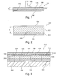
- FIG. 1 shows a cross-sectional view of a surface laying unit 100 according to an exemplary embodiment of the invention.
- the surface laying unit 100 is designed for common laying with other, similar surface laying units 100 to a continuous parquet.
- FIG. 1 shows that the surface laying unit 100 has a hard facing layer 102 of surface-coated (coated) solid wood as a surface layer, that is, the hard facing layer 102 forms the surface of the sub-floor covering when the surface laying unit 100 is laid.
- the hard covering layer 102 has a thickness d of 3 mm in this embodiment.
- a continuous foam layer as Schalldämpftechnik 110 is attached directly to the underside of the hard lining layer 102. This is designed to attenuate acoustic waves or sound generated upon exertion of a step load on the hard covering layer 102 or to suppress further sound development.
- the hard covering layer 102 consists of a single-material wood layer 125, which in this exemplary embodiment is covered on the surface with a layer of protective lacquer (or oil) 106.
- the protective varnish (or oil) 106 is a highly elastic varnish on the surface of the surface laying unit 100, which is exposed to the direct exertion of mechanical and chemical influences.
- This lacquer is configured to follow the leveling motion of the thin hard facing 102 elastically (i.e., without breaking or plastic deformation) and to shield mechanical impacts on the surface of the hard facing 102 from the wood layer 125.
- a magnetic mat 104 is glued to the wood layer 125.
- the magnetic mat 104 generates a magnetic force and thereby serves as a connecting layer for releasably connecting to a top-side corresponding magnetic mat of a subgrade laying unit, as further referring to FIG FIG. 2 is described.
- FIG. 12 shows a cross-sectional view of a floor or underground laying unit 200 that may be laid on a substrate in accordance with an exemplary embodiment of the invention in combination with the surface laying unit 100 to form an assembly.
- the underground laying unit 200 has on the upper side a magnetic mat 104 configured to form an attracting magnetic force with the magnetic mat 104 on the underside of the surface laying unit 100.
- a stability layer 202 made of a wood material.
- a Gegenzugfurnier für 204 also made of a wood material, is provided.
- the stability layer 202 has a relatively high thickness b of, for example, 20 mm, whereas the Jacobkarfurnier Anlagen 204 has a relatively small thickness of, for example, 1.5 mm.
- another magnetic layer 104 is provided, which is arranged to be connected to a magnetic layer on an on-site substrate 300, as referring to FIG FIG. 3 is described below.
- cavities for example, on the underside of the underground laying unit 200 may be formed, can be performed by the lines of a heater, air ducts or other components.
- FIG. 3 shows a cross-sectional view of an assembly 310 of underground laying units 200 according to FIG. 2 and surface laying units 100 according to FIG FIG. 1 .
- the underground laying units 200 on an on-site substrate 300, on top of which also a magnetic layer 104 may be arranged, placed.
- the surface laying units 100 are placed without adhesive on the underground laying units 100, whereby a releasable connection can also be created by the two corresponding magnetic layers 104. This results in the formation of the parquet 320 as an assembly 310 laid on the substrate 300.
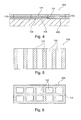
- FIG. 4 shows an arrangement 400 in which surface laying units 100 according to FIG. 1 are laid directly on the on-site substrate 300, which in turn is covered with a magnetic layer 104.
- FIG. 5 shows a plan view of a surface laying unit 500 according to an embodiment of the invention, in which the sound-damping structure not like in FIG. 1 in the form of a full-surface layer, but in the form of spaced, separate foam strips 110 are attached to the underside of the hard facing layer 102.
- FIG. 6 shows a structured Schalldämpf für 110, in which rectangular recesses are formed, so that a material-saving and lightweight surface laying unit 600 is formed.
- FIG. 7 shows a surface laying unit 700 applied to a screed 300, which is attached to the screed 300 by means of an adhesive layer 702. Furthermore, in addition to the sound-damping structure 110 on the underside of the hard-facing layer 102, an additional sound-damping layer 110 'is shown between the adhesive 702 and a stability layer 202.
- a first side surface of the surface laying unit 700 has a groove 750, and a second side surface of the surface laying unit 700 has a spring 752 complementary to the groove 750.
- the groove 750 is provided with a corresponding spring (not shown) and the spring 752 is provided with a corresponding groove (Fig. not shown) of corresponding surface laying units (not shown) connectable, whereby a positive connection of each adjacent surface laying units is made possible.
- FIG. 8 shows how FIG. 7 , designed as a veneer wear layer, which is referred to as hard facing layer 102.
- FIG. 8 differs from FIG. 7 by omitting the stability layer 202, providing only one silencing layer 100 and replacing the adhesive layer 702 with two corresponding magnetic mats 104, 104 ', one of which is applied to the underside of the surface laying unit 800 and the other to the top of the screed 300.
- FIG. 9 1 shows a surface laying unit 900 according to another exemplary embodiment of the invention, which differs from the surface laying unit 800 in that between the lower magnetic mat 104 'and the screed 300 still a support structure 902 for accommodating lines (for example for purposes of heating, cooling, Ventilation of electrical lines, or as sound-insulating materials) is arranged.
- lines for example for purposes of heating, cooling, Ventilation of electrical lines, or as sound-insulating materials
- FIG. 10 shows a laid on a screed 300 surface laying unit 1000 according to yet another embodiment of the invention, which is formed by the provision of a hard facing layer 102 on both sides as a turning structure 1002 and is symmetrical with respect to the connecting layer 104.
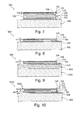
- FIG. 11 is a photograph of a surface laying unit 1100 according to an exemplary embodiment, here the sound damping structure in a direction perpendicular to the layer arrangement of the layers 202, 110, 102 consists of different materials.
- an edge region as indicated by reference numeral 1104, fewer flexible foam regions are provided than in a central region 1102, which has a higher soft elasticity.
- FIG. 12 shows a surface laying unit 1200 according to another exemplary embodiment of the invention, wherein here on the underside of the surface laying unit 1200 still another, thicker foam layer 110 'is provided.
- FIG. 13 shows a turning structure 1300 according to an exemplary embodiment of the invention in which two identical hard facing layers 102 face each other and are separated by a silencing layer 110.
- Optional protective coating layers 106 are provided on both surfaces.
- FIG. 14 Figure 14 shows an assembly 1400 according to an exemplary embodiment of the invention in a cross-sectional view, wherein surface laying units of magnetic mat 104, sound damping layer 110 and wear layer 102 are laid on horizontal surfaces of stair steps 1402 of a staircase which are covered with magnetic mats 104 as bonding layers.
- FIG. 15 FIG. 12 shows a surface laying unit 1500 according to an exemplary embodiment of the invention in which an optically transparent and soft sound absorbing structure 110 forms a surface layer to which is directly attached a hard facing layer 102 of solid wood.
- An optional tie layer 104 is also provided.
- FIG. 16 shows a surface laying unit 1600 laid on a substrate according to an exemplary embodiment of the invention, in which the sound damping structure 110 has areas 1604, 1606 of different hardness and material-free buffer areas 1602.
- the surface laying unit 1600 according to FIG. 16 is similarly configured as the surface laying unit 700 according to FIG FIG. 7 , FIG. 16 thus shows a further arrangement possibility of a combination of different layer thicknesses and curing a Schalldämpf Modell. An advantage of this is that the attenuation path can be limited with it.
- the silencing structure 110 is split into an array of laterally alternating substructures 1606, 1604.
- First substructures 1604 have a material with a higher hardness than second substructures 1606.
- the soft substructures 1606 are formed continuously and without interruption from a homogeneous material.
- the harder substructures 1604 are formed in a contact area to the hard facing layer 102 of a homogeneous material, whereas an end region of the substructures 1604 facing away from the hard facing layer 102 has a material-free free space 1602 as an escape buffer.
- the softer substructures 1606 may first yield and be compressed. After some time and some compression, a lower surface of the harder substructures 1604 then settles on the backing so that continued compression movement is allowed only to a very limited extent. On the other hand, it can be made possible by the compression along a defined and restricted path.
- the soft core yields until the hard core (reference numeral 1604) touches the ground. It has been found that this configuration is very advantageous with regard to the damping properties and the mechanical properties, in particular when laying several surface laying units 1600 next to one another in the composite.
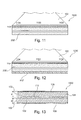
- FIG. 17 FIG. 16 shows a diagram 1700, which shows that the provision of the sound damping structure in combination with a thin hard covering layer can achieve significant sound damping.
- a region 1780 of the diagram 1700 the result of a measurement of airborne sound is plotted. This means that in an acoustic laboratory after the impact of a hammer blow on a respective laying unit, the sound development in the room was recorded with a microphone.
- a first trace 1710 refers to a reference sample. As a reference sample, a conventional two-layer parquet with a wear layer and a stability layer was used.
- a second measurement curve 1720 relates to a laying unit according to an embodiment of the invention. This laying unit contains compared to the reference sample an additional silencing layer directly between the wear layer and the stability layer.
- a third measurement curve 1730 relates to a laying unit with pad according to another embodiment of the invention. This laying unit contains, in addition to the laying unit described above, a further sound-damping layer between a substrate on which the respective laying units have been laid, and the stability layer.
- a region 1790 of the diagram 1700 the result of a measurement of structure-borne sound is plotted.
- self-measurement was performed on the three samples, as described above, ie their vibration behavior was recorded after exercise of the load by means of the hammer.
- a first trace 1740 relates to the reference sample.
- a second measurement curve 1750 relates to the laying unit according to measurement curve 1720.
- a third measurement curve 1760 relates to the laying unit according to measurement curve 1730.
- FIG. 18 shows another surface laying unit 1800 according to the invention (having a structure according to the features described above, see, for example FIG. 1 ), which is designed as a double floor laying unit with a spacer in the form of supports 1802 spaced from a substrate.
- a raised floor in this context, a second floor, i. spaced from, understood the actual underground of the room. As a result, each point of the room below the double floor remains accessible at all times. As a result, a raised floor is particularly suitable for rooms with frequent changes to the installations and if the installations are to be quickly accessible at all times.
- the supports 1802 between the substrate and the multi-layer structure 106, 125, 110, 104 are used as spacers.
- any functional elements may be accommodated, such as conduits 1804, electric cables 1806, etc.
- FIG. 19 shows an arrangement of double floor laying units 1800 according to the invention FIG. 18 , In FIG. 18 Further functional elements in the form of electrical appliances 1900 are shown, which can be electrically supplied or interconnected by means of the electric cables 1806.
- FIG. 20 shows another surface laying unit 2000 according to the invention, which can be laid on a substrate without underground laying unit.
- FIG. 12 shows another surface laying unit 2100 according to the invention, in which the sound-damping layer 110 is formed from a glass fiber mat 110b as an upper-side stabilizing sub-layer and from a lower-side foam layer 110a as a damping sub-layer.
- the foam layer 110a may be glued, in particular glued, to the glass fiber mat 110b.
- the foam layer 110a may be disposed on the upper side and the glass fiber mat 110b on the underside.
- the glass fiber mat 110b has a function of stabilizing the wood layer 125 with continued working (i.e., continued gentle movement) of the wood layer 125 after the laying of the surface laying unit 2100.
- the glass fiber mat 110b blocks the wood layer 125, i. reduces or prevents this work.
- liquid adhesive may be applied to the underside of the wood layer 125. After placing the glass fiber mat 110b and then the foam layer 110a to the underside of the wood layer 125, the liquid adhesive first penetrates the glass fiber mat 110b and then the foam layer 110a, thus providing intimate bonding of these components.
- FIG. 12 shows yet another surface laying unit 2200 according to the invention, in which the sound-damping layer 110 is formed from a foam layer 110a as the core layer and from two glass-fiber mats 110b, 110c as stabilization partial layers.
- the foam layer 110a is covered on the upper side and lower side by a respective one of the two glass fiber mats 110b, 110c.
- FIG. 23 shows another surface laying unit 2300 according to the invention, which is laid on a substrate together with a subgrade laying unit.
- a releasable bonding layer for example, a magnetic mat
- FIG. 23 shows another surface laying unit 2300 according to the invention, which is laid on a substrate together with a subgrade laying unit.
- a releasable bonding layer for example, a magnetic mat
Landscapes
- Engineering & Computer Science (AREA)
- Architecture (AREA)
- Civil Engineering (AREA)
- Structural Engineering (AREA)
- Life Sciences & Earth Sciences (AREA)
- Wood Science & Technology (AREA)
- General Engineering & Computer Science (AREA)
- Floor Finish (AREA)
- Road Paving Structures (AREA)
- Building Environments (AREA)
Priority Applications (1)
| Application Number | Priority Date | Filing Date | Title |
|---|---|---|---|
| EP12165794.4A EP2543792A3 (fr) | 2011-05-16 | 2012-04-26 | Système de revêtement de sol et mural doté d'unités de pose à isolation acoustique |
Applications Claiming Priority (4)
| Application Number | Priority Date | Filing Date | Title |
|---|---|---|---|
| EP11166261 | 2011-05-16 | ||
| EP11167166 | 2011-05-23 | ||
| EP11170412 | 2011-06-17 | ||
| EP12165794.4A EP2543792A3 (fr) | 2011-05-16 | 2012-04-26 | Système de revêtement de sol et mural doté d'unités de pose à isolation acoustique |
Publications (2)
| Publication Number | Publication Date |
|---|---|
| EP2543792A2 true EP2543792A2 (fr) | 2013-01-09 |
| EP2543792A3 EP2543792A3 (fr) | 2013-12-11 |
Family
ID=45976211
Family Applications (2)
| Application Number | Title | Priority Date | Filing Date |
|---|---|---|---|
| EP12165794.4A Withdrawn EP2543792A3 (fr) | 2011-05-16 | 2012-04-26 | Système de revêtement de sol et mural doté d'unités de pose à isolation acoustique |
| EP12717694.9A Active EP2710203B1 (fr) | 2011-05-16 | 2012-04-26 | Système de revêtement de sol ou mural possédant des unités de pose combinables de manière modulaire |
Family Applications After (1)
| Application Number | Title | Priority Date | Filing Date |
|---|---|---|---|
| EP12717694.9A Active EP2710203B1 (fr) | 2011-05-16 | 2012-04-26 | Système de revêtement de sol ou mural possédant des unités de pose combinables de manière modulaire |
Country Status (5)
| Country | Link |
|---|---|
| US (1) | US9890540B2 (fr) |
| EP (2) | EP2543792A3 (fr) |
| CN (1) | CN103649440B (fr) |
| DE (1) | DE202012013538U1 (fr) |
| WO (1) | WO2012156192A1 (fr) |
Cited By (1)
| Publication number | Priority date | Publication date | Assignee | Title |
|---|---|---|---|---|
| CN104929350A (zh) * | 2015-06-30 | 2015-09-23 | 中民筑友有限公司 | 一种瓷砖反打模板及反打方法 |
Families Citing this family (33)
| Publication number | Priority date | Publication date | Assignee | Title |
|---|---|---|---|---|
| US10794067B2 (en) * | 2013-06-14 | 2020-10-06 | Phillip Busby | Flooring support system |
| CA2879036C (fr) | 2014-01-27 | 2022-03-22 | Building Materials Investment Corporation | Materiau de couverture |
| DE102015003664A1 (de) | 2015-03-20 | 2016-10-06 | Weitzer Holding Gmbh | Wechselbelag mit Steckverbindung |
| CA3018500A1 (fr) * | 2015-03-27 | 2016-10-06 | Golconda Holdings Llc | Systeme, procede et appareil associes a des revetements magnetiques de surfaces |
| US10208489B2 (en) * | 2015-03-30 | 2019-02-19 | Exploring, Inc. | Raised flooring system and assembly method with magnetically-attached flooring surface |
| US10472832B2 (en) * | 2015-06-29 | 2019-11-12 | Cory Halischuk | Kits of parts for trimming step edges |
| US9328520B1 (en) * | 2015-07-17 | 2016-05-03 | Matthew Kriser | High strength in-floor decoupling membrane |
| ITUB20153663A1 (it) * | 2015-09-16 | 2017-03-16 | Bassi Group Int S R L | Manufatto per il rivestimento di superfici e relativi procedimenti di realizzazione e di posa |
| US10053869B2 (en) * | 2016-03-04 | 2018-08-21 | Kablan Developments Inc. | Tiling laminate, process, and use |
| ITUA20163380A1 (it) * | 2016-05-12 | 2017-11-12 | Metaly S R L | Pavimento con posa rapida e riscaldamento opzionale |
| DE202016107369U1 (de) | 2016-12-23 | 2017-02-01 | Weitzer Parkett Gmbh & Co. Kg | Untergrundbelag mit Sollbruchstelle |
| TW201842264A (zh) * | 2017-04-18 | 2018-12-01 | 英商英威達紡織(英國)有限公司 | 易安裝的陶瓷或石磚產品 |
| CN111601530A (zh) * | 2017-06-20 | 2020-08-28 | 宝山控股有限责任公司 | 用于覆盖地板、墙和其它表面的模块化的磁接受性木材和经设计的木材表面单元以及磁性箱系统 |
| US20190218795A1 (en) * | 2018-01-12 | 2019-07-18 | Hans-Erik Blomgren | Acoustically Absorptive Solid Volume Building Assembly |
| US11453195B2 (en) | 2018-07-23 | 2022-09-27 | Cintas Corporate Services, Inc. | Deconstructed floor mat |
| US11352792B2 (en) | 2018-08-06 | 2022-06-07 | Bmic Llc | Roofing shingle system and shingles for use therein |
| EP3643852A1 (fr) * | 2018-10-23 | 2020-04-29 | Scalarium Oy | Marche d'escalier et superposition de marches d'escalier |
| US11111676B2 (en) * | 2018-10-30 | 2021-09-07 | Summit Stairs of Atlanta, Inc. | Prefabricated stair components and stair tread finish systems and methods of making and using the same |
| EP3706516B1 (fr) * | 2019-03-07 | 2024-11-20 | !OBAC Limited | Système de plancher dissipatif statique |
| CN110388021B (zh) * | 2019-08-02 | 2020-03-13 | 赫红建筑设计(广东)有限公司 | 一种强化复合地板 |
| US11274433B2 (en) | 2019-11-16 | 2022-03-15 | Jeremy Britton | Linkable tiles for covering a surface |
| US12234653B2 (en) | 2019-11-16 | 2025-02-25 | Jeremy Britton | Linkable tiles for covering a surface |
| WO2021096543A1 (fr) | 2019-11-16 | 2021-05-20 | Jeremy Britton | Carreaux reliables pour recouvrir une surface |
| CA215335S (en) | 2020-02-29 | 2023-01-10 | Bmic Llc | Shingle |
| USD990712S1 (en) | 2020-03-05 | 2023-06-27 | Summit Stairs of Atlanta, Inc. | Stair tread |
| USD963199S1 (en) | 2020-03-05 | 2022-09-06 | Summit Stairs of Atlanta, Inc. | Stair tread |
| US20210396025A1 (en) * | 2020-06-17 | 2021-12-23 | Praters Incorporated | Modular flooring system and subfloor assembly |
| EP4060141B1 (fr) | 2021-03-18 | 2024-01-03 | Weitzer Holding GmbH | Unité de sous-couche auto-stabilisante et revêtement de sous-couche |
| NL2028139B1 (en) * | 2021-05-04 | 2022-11-10 | Goflow Tech Ip B V | Raised ventilation flooring structure |
| US11530540B2 (en) * | 2021-05-12 | 2022-12-20 | Pliteq Inc. | Sound transmission control in cross laminated timber construction |
| US12276105B2 (en) | 2021-08-26 | 2025-04-15 | Bmic Llc | Roofing shingles with a plurality of indentations |
| CN115492386B (zh) * | 2022-08-22 | 2025-01-14 | 徐州淮声电力工程有限公司 | 一种导电高熵合金复合铺装板材同冷热机组合安装的方法 |
| US20250198173A1 (en) * | 2023-12-13 | 2025-06-19 | United States Gypsum Company | Acoustic isolators |
Citations (4)
| Publication number | Priority date | Publication date | Assignee | Title |
|---|---|---|---|---|
| EP1116626A2 (fr) | 2000-01-10 | 2001-07-18 | Still Wagner GmbH & Co. KG | Convoyeur avec strapontin |
| EP1116716A1 (fr) | 1987-06-22 | 2001-07-18 | Eisai Co., Ltd. | Composés de pipéridines et pipérazines pour l'utilisation dans le traitement d'Alzheimer |
| EP1117041A2 (fr) | 2000-01-10 | 2001-07-18 | Sun Microsystems, Inc. | Méthode et appareil pour la gestion des pannes dans des systèmes d'ordinateurs groupés |
| US20110061324A1 (en) * | 2007-04-12 | 2011-03-17 | Tinianov Brandon D | Sound Proofing Material With Improved Damping And Structural Integrity |
Family Cites Families (29)
| Publication number | Priority date | Publication date | Assignee | Title |
|---|---|---|---|---|
| US2151505A (en) * | 1936-11-19 | 1939-03-21 | Elmendorf Armin | End grain wood flooring |
| US3341996A (en) * | 1966-02-23 | 1967-09-19 | Gen Tire & Rubber Co | Floor structures comprising floor covering layer containing magnetic material |
| US3717247A (en) * | 1970-06-08 | 1973-02-20 | Armstrong Cork Co | Prefabricated flooring |
| US4233793A (en) * | 1975-07-07 | 1980-11-18 | Omholt Ray | Resiliently cushioned adhesive-applied wood flooring system and method of making the same |
| DE2739134A1 (de) | 1977-08-31 | 1979-03-15 | Rettenmaier Hartmut | Mobilhaftplatte |
| CA1199467A (fr) | 1982-08-26 | 1986-01-21 | Tate Architectural Products, Inc. | Carreau modulaire a dispositif de positionnement sur panneau amovible de plancher sureleve |
| DE3804995A1 (de) | 1988-02-18 | 1989-08-31 | Metall Plastik Gmbh & Co Kg | Bausatz mit einer abdeckplatte |
| DE4228597A1 (de) | 1992-08-27 | 1994-03-03 | Manfred Bittner | Materialbahn zum festen Aufbringen auf einer Unterlage und Verfahren zu deren Herstellung |
| SE503973C2 (sv) | 1994-12-13 | 1996-10-07 | Dan Johansson | Sätt att lägga golv där golvbrädorna är belagda med ett friktionsskikt |
| US5985398A (en) * | 1994-12-27 | 1999-11-16 | Manufacture De Lambton Ltee | Stairtread made of a combination of higher quality wood and lower quality material |
| DE19940837A1 (de) * | 1998-10-26 | 2000-11-23 | Karl Boeckl | Verlegesystem und Verlegeverfahren |
| DE19901595A1 (de) | 1999-01-16 | 2000-08-10 | Karl Kampka | Verfahren zum austauschbaren Belegen eines Bodens, einer Wand o. dgl. und Belag für Boden, Wand, Decke u. dgl. zum Verlegen nach dem Verfahren |
| BE1014345A3 (nl) * | 2001-08-14 | 2003-09-02 | Unilin Beheer Bv | Vloerpaneel en werkwijze voor het vervaardigen ervan. |
| US7785691B2 (en) * | 2002-08-20 | 2010-08-31 | Velcro Industries B.V. | Flexible building construction laminates with fasteners |
| DE10354789B4 (de) * | 2003-11-21 | 2011-12-15 | hülsta-werke Hüls GmbH & Co. KG. | Paneel und Belag |
| KR200357517Y1 (ko) * | 2004-04-23 | 2004-07-30 | 주식회사 엘지화학 | 고강성 샌드위치 상판을 적용한 주택용 이중바닥 시스템 |
| US20060080910A1 (en) * | 2004-10-07 | 2006-04-20 | Silvano Cornia | Groutless tile system |
| WO2006075198A1 (fr) | 2005-01-13 | 2006-07-20 | Anthem Leather, Inc | Revetement modulaire magnetique |
| US8079184B2 (en) * | 2005-08-09 | 2011-12-20 | W. R. Grace & Co.-Conn. | Skid resistant surfaces |
| BRMU8502680U (pt) * | 2005-11-23 | 2007-07-24 | Jacob Abrahams | disposições introduzidas em elementos juncionadores de réguas formadoras de revestimento para contrapiso |
| US7401442B2 (en) * | 2006-11-28 | 2008-07-22 | Roger A Clark | Portable panel construction and method for making the same |
| DE102007038669A1 (de) | 2007-07-13 | 2009-01-15 | Parador Gmbh & Co. Kg | Bauteil mit nanoskaliger Funktionsschicht und dessen Verwendung |
| EP2185778A4 (fr) * | 2007-08-03 | 2012-02-01 | Tac Fast Systems Sa | Procédé d'installation d'une couverture de surface, et appareil associé |
| DE102007043202A1 (de) | 2007-09-11 | 2009-03-26 | Guido Schulte | Fußboden-, Wand- oder Deckenpaneele sowie Verfahren zu deren Herstellung |
| EP2182135A1 (fr) * | 2008-10-28 | 2010-05-05 | Tarkett GDL S.A. | Revêtement de surface amovible |
| EP2206850A1 (fr) | 2009-01-13 | 2010-07-14 | Christoph Gruss | Procédé d'établissement d'une fixation réversible d'un revêtement sur une couche de base |
| EP2258899A1 (fr) * | 2009-06-02 | 2010-12-08 | Tarkett GDL S.A. | Structure magnétique stratifiée |
| CN201460144U (zh) | 2009-07-02 | 2010-05-12 | 陈跃龙 | 一种多层实木地板 |
| PT104852B (pt) * | 2009-11-27 | 2013-07-15 | Amorim Cork Composites S A | Painéis laminados com propriedades melhoradas de isolamento acústico |
-
2012
- 2012-04-26 EP EP12165794.4A patent/EP2543792A3/fr not_active Withdrawn
- 2012-04-26 EP EP12717694.9A patent/EP2710203B1/fr active Active
- 2012-04-26 US US14/118,549 patent/US9890540B2/en active Active
- 2012-04-26 CN CN201280033801.7A patent/CN103649440B/zh not_active Expired - Fee Related
- 2012-04-26 DE DE202012013538.4U patent/DE202012013538U1/de not_active Expired - Lifetime
- 2012-04-26 WO PCT/EP2012/057688 patent/WO2012156192A1/fr not_active Ceased
Patent Citations (4)
| Publication number | Priority date | Publication date | Assignee | Title |
|---|---|---|---|---|
| EP1116716A1 (fr) | 1987-06-22 | 2001-07-18 | Eisai Co., Ltd. | Composés de pipéridines et pipérazines pour l'utilisation dans le traitement d'Alzheimer |
| EP1116626A2 (fr) | 2000-01-10 | 2001-07-18 | Still Wagner GmbH & Co. KG | Convoyeur avec strapontin |
| EP1117041A2 (fr) | 2000-01-10 | 2001-07-18 | Sun Microsystems, Inc. | Méthode et appareil pour la gestion des pannes dans des systèmes d'ordinateurs groupés |
| US20110061324A1 (en) * | 2007-04-12 | 2011-03-17 | Tinianov Brandon D | Sound Proofing Material With Improved Damping And Structural Integrity |
Cited By (1)
| Publication number | Priority date | Publication date | Assignee | Title |
|---|---|---|---|---|
| CN104929350A (zh) * | 2015-06-30 | 2015-09-23 | 中民筑友有限公司 | 一种瓷砖反打模板及反打方法 |
Also Published As
| Publication number | Publication date |
|---|---|
| DE202012013538U1 (de) | 2017-08-07 |
| WO2012156192A1 (fr) | 2012-11-22 |
| EP2543792A3 (fr) | 2013-12-11 |
| US9890540B2 (en) | 2018-02-13 |
| US20140283468A1 (en) | 2014-09-25 |
| EP2710203A1 (fr) | 2014-03-26 |
| CN103649440A (zh) | 2014-03-19 |
| EP2710203B1 (fr) | 2018-12-19 |
| CN103649440B (zh) | 2018-08-24 |
Similar Documents
| Publication | Publication Date | Title |
|---|---|---|
| EP2543792A2 (fr) | Système de revêtement de sol et mural doté d'unités de pose à isolation acoustique | |
| EP1262607B1 (fr) | Procédé de fabrication d'un panneau pour revêtement de sol | |
| EP1898025B1 (fr) | Panneau doté d'une isolation sonore contre le bruit de pas et le bruit ambiant, revêtement constitué de panneaux, couche de revêtement réduisant le bruit, son procédé de fabrication et dispositif associé | |
| EP1634696A1 (fr) | Elément pour revêtement de sol | |
| DE102012000468A1 (de) | Bodenpaneel und Verfahren zu seiner Herstellung | |
| DE202015106139U1 (de) | Unterlegematte für Fußbodenbeläge | |
| EP1219760B2 (fr) | Système d'isolant acoustique mixte pour les surfaces délimitant des espaces | |
| EP3070231A1 (fr) | Semelle interchangeable comprenant un connecteur a fiches | |
| DE10354789A1 (de) | Paneel, Belag und Verfahren zum Verlegen eines Belages | |
| EP1113122B1 (fr) | Système composite acoustique pour les délimitations spatiales | |
| EP2230364B1 (fr) | Plaque de sol dotée d'une surface en pierre | |
| DE102005021662A1 (de) | Fußbodenpaneele | |
| WO2006119807A1 (fr) | Panneau dote d'une isolation sonore, a deux couches, contre les bruits de pas | |
| DE202007007372U1 (de) | Entkopplungssystem | |
| DE20207985U1 (de) | Tritt- und Raumschalldämmung, Körperschalldämmung aus vernetzten Natur- und/oder Syntheselatex für Hartfußbodenbelege z.B. Laminatboden-Paneele | |
| DE102019128891B3 (de) | Wiederaufnahmefähiger Bodenaufbau mit Fliesen und Verfahren zur Errichtung desselben | |
| EP2977524B1 (fr) | Panneau en bois à émission sonore réduite et son procédé de fabrication | |
| DE202016107369U1 (de) | Untergrundbelag mit Sollbruchstelle | |
| EP1544374B1 (fr) | Revêtement de marches d'escalier avec des éléments de revêtement sous la forme de couche de granulats comprenant des substances minérales, escalier avec un tel revêtement et usage d'un tel revêtement | |
| DE102010037080A1 (de) | Unterbodenelement | |
| AT523375A2 (de) | Bodenbelagsanordnung | |
| DE102025115263A1 (de) | Bodenbelagselement zur losen Verlegung sowie Herstellungsverfahren für ein Bodenbelagselement | |
| WO2002101167A2 (fr) | Element d'insonorisation | |
| EP1596028A2 (fr) | Plancher en dalles en mortier d'aire et ensemble de construction pour sa production | |
| JP6813412B2 (ja) | 土間用床材 |
Legal Events
| Date | Code | Title | Description |
|---|---|---|---|
| PUAI | Public reference made under article 153(3) epc to a published international application that has entered the european phase |
Free format text: ORIGINAL CODE: 0009012 |
|
| AK | Designated contracting states |
Kind code of ref document: A2 Designated state(s): AL AT BE BG CH CY CZ DE DK EE ES FI FR GB GR HR HU IE IS IT LI LT LU LV MC MK MT NL NO PL PT RO RS SE SI SK SM TR |
|
| AX | Request for extension of the european patent |
Extension state: BA ME |
|
| PUAL | Search report despatched |
Free format text: ORIGINAL CODE: 0009013 |
|
| AK | Designated contracting states |
Kind code of ref document: A3 Designated state(s): AL AT BE BG CH CY CZ DE DK EE ES FI FR GB GR HR HU IE IS IT LI LT LU LV MC MK MT NL NO PL PT RO RS SE SI SK SM TR |
|
| AX | Request for extension of the european patent |
Extension state: BA ME |
|
| RIC1 | Information provided on ipc code assigned before grant |
Ipc: E04F 11/108 20060101ALI20131107BHEP Ipc: E04F 13/08 20060101ALI20131107BHEP Ipc: E04F 15/18 20060101ALI20131107BHEP Ipc: E04F 15/20 20060101ALI20131107BHEP Ipc: E04F 13/10 20060101ALI20131107BHEP Ipc: E04F 11/104 20060101ALI20131107BHEP Ipc: E04F 15/04 20060101AFI20131107BHEP Ipc: E04F 15/02 20060101ALI20131107BHEP Ipc: E04F 11/17 20060101ALI20131107BHEP |
|
| 17P | Request for examination filed |
Effective date: 20140611 |
|
| RBV | Designated contracting states (corrected) |
Designated state(s): AL AT BE BG CH CY CZ DE DK EE ES FI FR GB GR HR HU IE IS IT LI LT LU LV MC MK MT NL NO PL PT RO RS SE SI SK SM TR |
|
| 17Q | First examination report despatched |
Effective date: 20151126 |
|
| STAA | Information on the status of an ep patent application or granted ep patent |
Free format text: STATUS: EXAMINATION IS IN PROGRESS |
|
| STAA | Information on the status of an ep patent application or granted ep patent |
Free format text: STATUS: THE APPLICATION IS DEEMED TO BE WITHDRAWN |
|
| 18D | Application deemed to be withdrawn |
Effective date: 20170504 |