EP2543894B1 - Verfahren zur Herstellung eines Verbindungselementes für rohrförmige Elemente zur Erstellung einer Struktur und entsprechendes Verbindungselement - Google Patents
Verfahren zur Herstellung eines Verbindungselementes für rohrförmige Elemente zur Erstellung einer Struktur und entsprechendes Verbindungselement Download PDFInfo
- Publication number
- EP2543894B1 EP2543894B1 EP12174353.8A EP12174353A EP2543894B1 EP 2543894 B1 EP2543894 B1 EP 2543894B1 EP 12174353 A EP12174353 A EP 12174353A EP 2543894 B1 EP2543894 B1 EP 2543894B1
- Authority
- EP
- European Patent Office
- Prior art keywords
- bending
- shaped
- edge
- laminar body
- portions
- Prior art date
- Legal status (The legal status is an assumption and is not a legal conclusion. Google has not performed a legal analysis and makes no representation as to the accuracy of the status listed.)
- Not-in-force
Links
Images


Classifications
-
- F—MECHANICAL ENGINEERING; LIGHTING; HEATING; WEAPONS; BLASTING
- F16—ENGINEERING ELEMENTS AND UNITS; GENERAL MEASURES FOR PRODUCING AND MAINTAINING EFFECTIVE FUNCTIONING OF MACHINES OR INSTALLATIONS; THERMAL INSULATION IN GENERAL
- F16B—DEVICES FOR FASTENING OR SECURING CONSTRUCTIONAL ELEMENTS OR MACHINE PARTS TOGETHER, e.g. NAILS, BOLTS, CIRCLIPS, CLAMPS, CLIPS OR WEDGES; JOINTS OR JOINTING
- F16B7/00—Connections of rods or tubes, e.g. of non-circular section, mutually, including resilient connections
- F16B7/04—Clamping or clipping connections
- F16B7/044—Clamping or clipping connections for rods or tubes being in angled relationship
- F16B7/048—Clamping or clipping connections for rods or tubes being in angled relationship for rods or for tubes without using the innerside thereof
- F16B7/0486—Clamping or clipping connections for rods or tubes being in angled relationship for rods or for tubes without using the innerside thereof forming an abutting connection of at least one tube
Definitions
- connection element that can be used to mutually connect a plurality of tubular elements in order to form a structure.
- a corner element of known type comprises a plurality of seats suited to house the ends of the same number of tubular elements making up the structure, which can be fixed to the corner element by means of screws or other fastening means of known type.
- the corner element comprises three seats configured so as to house three corresponding tubular elements arranged in mutually orthogonal directions.
- the corner element is produced from a metal sheet which is bent to form a dihedron, on the edges of which projections are welded which provide the seats for the tubular elements.
- This type of corner element poses the drawback of being relatively laborious to produce, as it requires welding of the above-mentioned projections.
- the welded parts pose the further drawback of reducing the resistance of the corner element, as they are more easily subject to breakage.
- the corner element is obtained by means of moulding of plastic material.
- This variant nevertheless poses the drawback of having a relatively limited structural resistance, which may be inadequate for the formation of some particularly large and/or heavy structures.
- the present invention aims to overcome all the above-mentioned drawbacks that are typical of the known art.
- the object of the present invention is to produce a corner element for structures with a high structural resistance, so that it can be used in applications for which a plastic corner element is not suitable.
- a further object of the invention is to provide a method that allows a corner element for structures to be produced in a simpler, quicker and cheaper manner compared to the methods of known type, the structural resistance being equal.
- the method of the invention makes it possible to reduce the time required for production of the corner element, therefore reducing its cost.
- connection element 1 shown in fig. 1 , suitable to mutually connect a plurality of tubular elements 2 making up a structure.
- Fig. 1 shows only the ends of the tubular elements 2 which, for the sake of clarity, are indicated by a broken line.
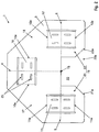
- connection element 1 a substantially flat shaped laminar body 3 is provided, made of a plastically deformable material, as shown in fig. 2 .
- the above-mentioned shaped laminar body 3 is obtained by shearing a metal sheet, for example made of steel.
- variant embodiments of the method of the invention may entail the use of materials other than the one described above, on condition that they are plastically deformable.
- the shaped laminar body 3 is bent along the bending lines 4, 5, 6 indicated by the broken line in fig. 2 , thus defining three concave areas 7, 8, 9, in each one of which a respective tubular element 2 can be rested.
- two of the above-mentioned bending lines 5 and 6 are aligned with each other in a direction perpendicular to the other bending line 4.
- the three concave areas 7, 8, 9 extend in three corresponding directions orthogonal to one another and allow three tubular elements 2 to be mutually arranged at right angles.
- the bending lines 4, 5, 6 converge in one single intersection point 16, highlighted in fig. 2 by a cross, and delimit three corresponding portions 17, 18,19 in the shaped laminar body 3.
- the bending lines 4, 5, 6 can have configurations that are different from the one described above, according to the preferred arrangement to be given to the tubular elements 2.
- the shaped laminar body 3 presents a perimeter profile that is symmetrical with respect to a first bending line 4 and the remaining two bending lines 5, 6 are arranged symmetrically with respect to the first bending line 4.
- the shaped laminar body 3 it is made a pair of cuts 4a-4a, 5a-5a, 6a-6a at the level of each bending line 4, 5, 6, the cuts of each pair being mainly developed along trajectories that intersect the corresponding bending line 4, 5, 6.
- each pair of cuts 4a-4a, 5a-5a, 6a-6a delimits laterally a corresponding strip 10, 11, 12 of material which remains connected to the shaped laminar body 3 at the level of two opposite edges 10a, 11a, 12a.
- the method comprises the further operation of lifting each strip 10, 11, 12 towards the inside of the corresponding concave area 7, 8, 9.
- the strip 10, 11, 12 and the areas of the shaped laminar body 3 adjacent to the cuts 4a, 5a, 6a delimit a guide channel 13, 14, 15 developed parallel to the bending line 4, 5, 6, suitable for slidingly housing one of the above-mentioned tubular elements 2.
- connection element 1 to be produced exclusively by means of cutting and bending operations and, therefore, without the need for welding.
- the method of the invention achieves the object of simplifying production of the connection element 1 with respect to the corner elements of known type.
- connection element 1 made of metallic material, in particular sheet steel.
- connection element 1 the absence of welded parts avoids the presence of weaker areas in the connection element 1, increasing the resistance thereof.
- connection element 1 which is more robust than those of the known type made of metallic or plastic material.
- the tubular elements 2 which are inserted in the respective guide channels 13, 14, 15 prevent the connection element 1 from moving apart along the bends, therefore increasing the rigidity thereof.
- the cuts 4a, 5a and 6a are in parallel pairs and have the same length.
- the guide channels 13, 14, 15 present a substantially constant cross section and lateral edges substantially perpendicular with respect to the corresponding bending lines 4, 5, 6.
- variant embodiments of the invention can comprise a number of strips different from the one indicated above, on condition that each strip is delimited laterally by a pair of cuts intersecting a corresponding bending line 4, 5, 6.
- each strip 10, 11, 12 is raised towards the inside of the corresponding concave area 7, 8, 9 simultaneously with the corresponding bending operation.
- each guide channel 13, 14, 15 to be obtained by means of one single bending operation, reducing the production time.
- the shaped laminar body 3 presents a perimeter profile which defines a recess 20.
- the above-mentioned recess 20 is provided with an open side 20a at the level of a portion 19 of the shaped laminar body 3 and extends at least as far as the point of intersection 16 of the bending lines 4, 5, 6.
- the recess 20 divides the above-mentioned portion 19 into two separate edge portions 21 and 22, opposing each other with respect to one of the above-mentioned bending lines which, preferably, is the first bending line 4.
- connection element 1 the presence of the above-mentioned recess 20 allows the three bends to be made independently of one another, facilitating the production of the connection element 1.
- the respective shaped edges 21 a, 22a adjacent to the recess 20 are configured so as to be arranged back to back following the above-mentioned bends, as can be seen in fig. 1 .
- the contact between the above-mentioned shaped edges 21a and 22a prevents crushing of the connection element 1 along the first bending line 4, increasing the rigidity of the connection element 1.
- the contact between the shaped edges 21a, 22a allows them to be welded if it is necessary to further increase the robustness of the shaped element.
- connection element in accordance with the invention illustrated in fig. 3 and indicated therein as a whole by 1' differs from the preceding one only due to the fact that the shaped edges 21a, 22a of the two edge portions 21, 22 define corresponding matching shaped portions 23, 24 suitable for interlocking with each other during bending of the edge portions 21, 22.
- the above-mentioned joint prevents the shaped edges 21a, 22a from moving apart, therefore improving the rigidity of the connection element 1'.
- the above-mentioned shaped portions comprise a projection 23 defined by the profile of the shaped edge 21a of the edge portion 21, which interlocks with a corresponding recess 24 defined by the profile of the shaped edge 22a belonging to the other edge portion 22.
- the method entails completion of the bending of the shaped laminar body 3' along the first bending line 4 and, subsequently, completion of the bending of one of the above-mentioned edge portions 21 or 22 along the respective bending line 5 , 6.
- the two edge portions 21, 22 are in a mutual position such that, during their subsequent bending, the corresponding shaped edges 21a, 22a interlock with each other.
- one of the edge portions 21 or 22 is bent completely along the respective bending line 5, 6, while the other edge portion is bent partially and the bending is completed after bending along the first bending line 4.
- each one of the strips 10, 11, 12 comprises one or more through holes 25 suited to house the end of a clamp for fixing a tubular element 2 after it has been inserted in the corresponding guide channel 13, 14, 15.
- the above-mentioned clamp can be a screw or an eccentric clamp, or of any known type.
- connection elements 1, 1' In practice, to obtain any one of the two connection elements 1, 1' described above, firstly the shaped laminar body 3, 3' is provided, obtaining it for example via shearing a metal sheet.
- the cuts 4a, 5a, 6a that define each strip 10, 11, 12, as well as the through holes 25 for fixing the tubular elements 2 are obtained simultaneously with the above-mentioned shearing process, ensuring rapidity of the operation.
- the above-mentioned operations can be carried out at different times.
- the shaped laminar body 3, 3' is bent along the three bending lines 4, 5, 6 and the strips are raised towards the inside of the concave areas 7, 8, 9 defined by the above-mentioned bends.
- the edge portions 21, 22 can be welded together at the level of the respective shaped edges 21a, 22a.
- connection element 1, 1' thus obtained can therefore be used to mutually connect three tubular elements 2 making up a structure, inserting each tubular element 2 in a corresponding guide channel 13, 14, 15 defined by each bend and by the corresponding raised strip 10, 11, 12.
- connection element 1, 1' can be configured so as to present any number of guide channels, on condition that they are produced as described above.
- connection element 1 described and shown herein features three corners orthogonal to one another, variant embodiments can feature corners with a different angle, by appropriate arrangement of the bending lines 4, 5, 6.
- the method of the invention makes it possible to produce a sheet metal connection element which is more robust and can be obtained in a simpler manner than allowed by the known methods.
- connection element to be obtained which, unlike the corner elements of known type obtained by sheet metal bending, does not require any welding.
Landscapes
- Engineering & Computer Science (AREA)
- General Engineering & Computer Science (AREA)
- Mechanical Engineering (AREA)
- Bending Of Plates, Rods, And Pipes (AREA)
- Piezo-Electric Or Mechanical Vibrators, Or Delay Or Filter Circuits (AREA)
Claims (8)
- Methode zur Herstellung eines Eckelements oder eines Verbindungselements (1; 1'), dazu geeignet, eine Vielzahl röhrenförmiger Elemente (2) miteinander zu verbinden und so eine Struktur zu bilden, folgende Vorgänge umfassend:- Beschaffung eines geformten, blätterförmigen Körpers (3; 3') aus einem plastisch verformbaren Material;- Biegen des besagten geformten, blätterförmigen Körpers (3; 3') entlang dreier Biegelinien (4, 5, 6), die in einem Schnittpunkt (16) konvergieren, um drei entsprechende Abschnitte (17, 18, 19) des besagten geformten, blätterförmigen Körpers (3; 3') zu begrenzen, um entsprechende, konkave Bereiche (7, 8, 9) für die Aufnahme der besagten, röhrenförmigen Elemente (2) zu definieren;- Ausführung in dem besagten geformten, blätterförmigen Körper (3; 3') von zwei überwiegend gemäß entsprechenden Trajektorien, die wenigstens eine der besagten Biegelinien (4, 5, 6) schneiden, verlaufenden Schnitten (4a, 5a, 6a), so dass sie seitlich einen entsprechenden Streifen (10, 11, 12) aus Material begrenzen, der auf Höhe von zwei einander entgegengesetzten Kanten (10a, 11a, 12a) mit dem besagten geformten, blätterförmigen Körper (3; 3') verbunden bleibt;- Anheben des besagten Streifens (10, 11, 12) zum Inneren des konkaven Bereichs (7, 8, 9) hin, der durch die entsprechende Biegelinie (4, 5, 6) definiert ist, so dass der besagte Streifen (10, 11, 12) und die Bereiche des besagten geformten, blätterförmigen Körpers (3; 3'), die an die besagten Schnitte (4a, 5a, 6a) angrenzen, einen Führungskanal (13, 14, 15) begrenzen, der parallel zu der besagten Biegelinie (4, 5, 6) verläuft, dazu geeignet, eines der besagte, röhrenförmigen Elemente (2) gleitend aufzunehmen;wobei das Umfangsprofil des besagten geformten, blätterförmigen Körpers (3; 3') eine Aussparung (20) mit einer offenen Seite (20a) auf Ebene eines der besagten Abschnitte (19) definiert, die sich wenigstens bis zu dem besagten Schnittpunkt (16) erstreckt, um den besagten Abschnitt (19) in zwei Kantenabschnitte (21, 22) zu teilen, die voneinander getrennt sind und einander bezüglich einer ersten der besagten Biegelinien (4) gegenüberliegen, wobei einer der besagten Kantenabschnitte (21, 22) eine geformte Kante (21 a, 22a) aufweist, die an die besagte Aussparung (20) angrenzt und so konfiguriert ist, dass sie nach den besagten Biegevorgängen an der entsprechenden, geformten Kante (21 a, 22a) des anderen Kantenabschnitts (21, 22) anliegend positioniert wird,
dadurch gekennzeichnet, dass die geformte Kante (21 a, 22a) eines der besagten Kantenabschnitte (21, 22) einen Vorsprung (23) umfasst, der dazu geeignet ist, während des Biegens der besagten Kantenabschnitte (21, 22) in eine entsprechende, zu der geformten Kante (21 a, 22a) des anderen Kantenabschnitts (21, 22) gehörende Aussparung (24) eingepasst zu werden, wobei die besagte Methode den Vorgang des Einpassens des besagten Vorsprungs (23) in die besagte Aussparung (24) umfasst. - Methode gemäß Patentanspruch 1), dadurch gekennzeichnet, dass der besagte Anhebevorgang gleichzeitig mit dem entsprechenden Biegevorgang ausgeführt wird.
- Methode gemäß eines jeden der vorstehenden Patentansprüche, dadurch gekennzeichnet, dass das Biegen von wenigstens eines der besagten Kantenabschnitte (21, 22) wenigstens teilweise nach dem Abschluss des Biegens entlang der besagten, ersten Biegelinie (4) ausgeführt wird.
- Methode gemäß eines jeden der vorstehenden Patentansprüche, dadurch gekennzeichnet, dass der besagte geformte, blätterförmige Körper (3) ein Umfangsprofil aufweist, das bezüglich der ersten Biegelinie (4) symmetrisch ist, während die verbleibenden zwei Biegelinien (5, 6) bezüglich der besagten, ersten Biegelinie (4) symmetrisch angeordnet ist.
- Methode gemäß eines jeden der vorstehenden Patentansprüche, dadurch gekennzeichnet, dass jeder der zwei Streifen (10, 11, 12) eine Durchgangsbohrung (25) umfasst, die geeignet ist, die Befestigung eines der besagten, röhrenförmigen Elemente (2) zuzulassen, nachdem es in den entsprechenden Führungskanal eingesetzt wurde (13, 14, 15).
- Methode gemäß eines jeden der vorstehenden Patentansprüche, dadurch gekennzeichnet, dass der besagte geformte, blätterförmige Körper (3; 3') durch Scheren eines Metallblechs erzielt wird.
- Geformter, blätterförmiger Körper (3; 3') aus plastisch verformbarem Material für die Verwendung mit einer Methode gemäß Patentanspruch 1), dazu geeignet, entlang dreier vorbestimmter Biegelinien (4, 5, 6), die in einem Schnittpunkt (16) konvergieren, um drei entsprechende Abschnitte (17, 18, 19) des besagten geformten, blätterförmigen Körpers (3; 3') zu begrenzen, gebogen zu werden, wobei der besagte geformte, blätterförmige Körper (3; 3') Folgendes umfasst:- zwei Schnitte (4a, 5a, 6a), die überwiegend gemäß entsprechenden Trajektorien, die wenigstens eine der besagten Biegelinien (4, 5, 6) schneiden, verlaufen, so dass sie seitlich einen entsprechenden Streifen (10, 11, 12) aus Material begrenzen, der auf Höhe von zwei einander entgegengesetzten Kanten (10a, 11a, 12a) mit dem besagten geformten, blätterförmigen Körper (3; 3') verbunden bleibt;- ein Umfangsprofil, das auf Höhe eines der besagten Abschnitte (19) eine Aussparung (20) mit einer offenen Seite (20a) aufweist, die sich wenigstens bis zu dem besagten Schnittpunkt (16) erstreckt, um den besagten Abschnitt (19) in zwei Kantenabschnitte (21, 22) zu teilen, die voneinander getrennt sind und einander bezüglich einer ersten der besagten Biegelinien (4) gegenüberliegen, wobei einer der besagten Kantenabschnitte (21, 22) eine geformte Kante (21 a, 22a) aufweist, die an die besagte Aussparung (20) angrenzt und so konfiguriert ist, dass sie nach den besagten Biegevorgängen an der entsprechenden, geformten Kante (21 a, 22a) des anderen Kantenabschnitts (21, 22) anliegend positioniert wird,dadurch gekennzeichnet, dass die geformte Kante (21 a, 22a) eines der besagten Kantenabschnitte (21, 22) einen Vorsprung (23) umfasst, der dazu geeignet ist, während des Biegens des besagten Kantenabschnitts (21, 22) entlang der entsprechenden Biegelinien (4, 5, 6) in eine entsprechende, zu der geformten Kante (21 a, 22a) des anderen Kantenabschnitts (21, 22) gehörende Aussparung (24) eingepasst zu werden.
- Eckelement oder Verbindungselement (1; 1') einer Vielzahl röhrenförmiger Elemente (2), die eine Struktur bilden, dadurch gekennzeichnet, dass es mittels einer Methode gemäß eines jeden der vorstehenden Patentansprüche von 1) bis 6) erzielt werden kann.
Applications Claiming Priority (1)
| Application Number | Priority Date | Filing Date | Title |
|---|---|---|---|
| IT000179A ITVI20110179A1 (it) | 2011-07-04 | 2011-07-04 | Metodo per la realizzazione di un elemento per il collegamento degli elementi tubolari componenti una struttura ed elemento di collegamento realizzato tramite tale metodo |
Publications (2)
| Publication Number | Publication Date |
|---|---|
| EP2543894A1 EP2543894A1 (de) | 2013-01-09 |
| EP2543894B1 true EP2543894B1 (de) | 2016-04-20 |
Family
ID=44513051
Family Applications (1)
| Application Number | Title | Priority Date | Filing Date |
|---|---|---|---|
| EP12174353.8A Not-in-force EP2543894B1 (de) | 2011-07-04 | 2012-06-29 | Verfahren zur Herstellung eines Verbindungselementes für rohrförmige Elemente zur Erstellung einer Struktur und entsprechendes Verbindungselement |
Country Status (2)
| Country | Link |
|---|---|
| EP (1) | EP2543894B1 (de) |
| IT (1) | ITVI20110179A1 (de) |
Families Citing this family (3)
| Publication number | Priority date | Publication date | Assignee | Title |
|---|---|---|---|---|
| CN103994134A (zh) * | 2013-02-18 | 2014-08-20 | 胡厚飞 | 组装架的接头及利用其所组成的组装架 |
| GB2586007B (en) * | 2019-07-09 | 2023-12-20 | Moonshine Investment Holdings Ltd | Multi-functional connector |
| FR3101119B1 (fr) * | 2019-09-25 | 2021-10-22 | Mkl | Ensemble de connexion d’éléments tubulaires |
Family Cites Families (7)
| Publication number | Priority date | Publication date | Assignee | Title |
|---|---|---|---|---|
| GB191115929A (en) * | 1911-07-10 | 1912-07-10 | Rohintan Nussurvanji Mirza | Improvements relating to Reinforced Concrete Construction. |
| GB744294A (en) * | 1951-06-11 | 1956-02-01 | Frank Bernard Harley | Improvements relating to joints for frameworks |
| US3062570A (en) * | 1959-11-04 | 1962-11-06 | Schwartz Metal Company Inc | Connector |
| US4136985A (en) * | 1977-07-07 | 1979-01-30 | Massey-Ferguson Inc. | Corner structure |
| US4968176A (en) * | 1988-02-29 | 1990-11-06 | Balach David M | Reinforcing bar coupling device |
| US5274981A (en) * | 1992-03-06 | 1994-01-04 | Simpson Strong-Tie Company, Inc. | Rim tie connection |
| DE102006020437A1 (de) * | 2006-05-03 | 2007-11-08 | A.P.S. Arosio S.R.L. | Verbindungsvorrichtung zum Verbinden von mehreren Profilstäben |
-
2011
- 2011-07-04 IT IT000179A patent/ITVI20110179A1/it unknown
-
2012
- 2012-06-29 EP EP12174353.8A patent/EP2543894B1/de not_active Not-in-force
Also Published As
| Publication number | Publication date |
|---|---|
| EP2543894A1 (de) | 2013-01-09 |
| ITVI20110179A1 (it) | 2013-01-05 |
Similar Documents
| Publication | Publication Date | Title |
|---|---|---|
| US12040743B2 (en) | Grounding clamps | |
| US9882289B2 (en) | Sheet metal part with improved connection tab geometry | |
| EP2543894B1 (de) | Verfahren zur Herstellung eines Verbindungselementes für rohrförmige Elemente zur Erstellung einer Struktur und entsprechendes Verbindungselement | |
| CN110431282A (zh) | 插接件和插接装置 | |
| US7021110B2 (en) | Apparatus for preparing U-shaped spacers for insulating units | |
| US10770856B2 (en) | Bent electric contact element with chamfered edges and method for its manufacture | |
| RU2013141510A (ru) | Способ изготовления прямоугольных или квадратных стеновых элементов из листового материала и стеновой элемент, полученный таким способом | |
| US20120131848A1 (en) | Vineyard Stake | |
| KR20140079949A (ko) | 롤 포밍 장치 | |
| JP2010070901A (ja) | グレーチングおよびその製造方法 | |
| CN217802132U (zh) | 设有弯刀槽的刀片及刀模 | |
| CN110165432B (zh) | 扁平线的前端部结构及其制造方法 | |
| JP5757430B2 (ja) | 端子金具 | |
| US11192321B2 (en) | Rigid sheet blank and method for producing same | |
| JP6431357B2 (ja) | 端子連鎖帯 | |
| KR20180084570A (ko) | 바인딩 프레임이 구성된 콘크리트 충전용 기둥 조립체의 제작방법 및 이에 의해 제작되는 기둥 조립체 | |
| EP2923779A1 (de) | Zaunpaneel | |
| JP2010146948A (ja) | 端子金具 | |
| JP2000218331A (ja) | 板材の接合方法と接合装置 | |
| US20080041555A1 (en) | Method and Apparatus for Counteracting Stress in a Metal Product | |
| JP2020163398A (ja) | 筒状部品およびその製造方法 | |
| US8234900B1 (en) | Corrugated metal sheet member fabrication system | |
| EP3498392A1 (de) | Starrer bogenrohling und verfahren zur herstellung davon | |
| JP2014079803A (ja) | 溶接用裏当金 | |
| EP2430254B1 (de) | Verbessertes kupplungselement für stangenförmige umgedrehte t-profile |
Legal Events
| Date | Code | Title | Description |
|---|---|---|---|
| PUAI | Public reference made under article 153(3) epc to a published international application that has entered the european phase |
Free format text: ORIGINAL CODE: 0009012 |
|
| AK | Designated contracting states |
Kind code of ref document: A1 Designated state(s): AL AT BE BG CH CY CZ DE DK EE ES FI FR GB GR HR HU IE IS IT LI LT LU LV MC MK MT NL NO PL PT RO RS SE SI SK SM TR |
|
| AX | Request for extension of the european patent |
Extension state: BA ME |
|
| 17P | Request for examination filed |
Effective date: 20130704 |
|
| RBV | Designated contracting states (corrected) |
Designated state(s): AL AT BE BG CH CY CZ DE DK EE ES FI FR GB GR HR HU IE IS IT LI LT LU LV MC MK MT NL NO PL PT RO RS SE SI SK SM TR |
|
| 17Q | First examination report despatched |
Effective date: 20141222 |
|
| GRAP | Despatch of communication of intention to grant a patent |
Free format text: ORIGINAL CODE: EPIDOSNIGR1 |
|
| INTG | Intention to grant announced |
Effective date: 20150818 |
|
| GRAP | Despatch of communication of intention to grant a patent |
Free format text: ORIGINAL CODE: EPIDOSNIGR1 |
|
| GRAJ | Information related to disapproval of communication of intention to grant by the applicant or resumption of examination proceedings by the epo deleted |
Free format text: ORIGINAL CODE: EPIDOSDIGR1 |
|
| GRAP | Despatch of communication of intention to grant a patent |
Free format text: ORIGINAL CODE: EPIDOSNIGR1 |
|
| INTG | Intention to grant announced |
Effective date: 20151020 |
|
| INTG | Intention to grant announced |
Effective date: 20151029 |
|
| GRAS | Grant fee paid |
Free format text: ORIGINAL CODE: EPIDOSNIGR3 |
|
| GRAA | (expected) grant |
Free format text: ORIGINAL CODE: 0009210 |
|
| AK | Designated contracting states |
Kind code of ref document: B1 Designated state(s): AL AT BE BG CH CY CZ DE DK EE ES FI FR GB GR HR HU IE IS IT LI LT LU LV MC MK MT NL NO PL PT RO RS SE SI SK SM TR |
|
| REG | Reference to a national code |
Ref country code: GB Ref legal event code: FG4D |
|
| REG | Reference to a national code |
Ref country code: CH Ref legal event code: EP |
|
| REG | Reference to a national code |
Ref country code: AT Ref legal event code: REF Ref document number: 792780 Country of ref document: AT Kind code of ref document: T Effective date: 20160515 |
|
| REG | Reference to a national code |
Ref country code: IE Ref legal event code: FG4D |
|
| REG | Reference to a national code |
Ref country code: DE Ref legal event code: R096 Ref document number: 602012017246 Country of ref document: DE |
|
| REG | Reference to a national code |
Ref country code: FR Ref legal event code: PLFP Year of fee payment: 5 |
|
| REG | Reference to a national code |
Ref country code: LT Ref legal event code: MG4D |
|
| REG | Reference to a national code |
Ref country code: AT Ref legal event code: MK05 Ref document number: 792780 Country of ref document: AT Kind code of ref document: T Effective date: 20160420 |
|
| REG | Reference to a national code |
Ref country code: NL Ref legal event code: MP Effective date: 20160420 |
|
| PG25 | Lapsed in a contracting state [announced via postgrant information from national office to epo] |
Ref country code: NO Free format text: LAPSE BECAUSE OF FAILURE TO SUBMIT A TRANSLATION OF THE DESCRIPTION OR TO PAY THE FEE WITHIN THE PRESCRIBED TIME-LIMIT Effective date: 20160720 Ref country code: FI Free format text: LAPSE BECAUSE OF FAILURE TO SUBMIT A TRANSLATION OF THE DESCRIPTION OR TO PAY THE FEE WITHIN THE PRESCRIBED TIME-LIMIT Effective date: 20160420 Ref country code: NL Free format text: LAPSE BECAUSE OF FAILURE TO SUBMIT A TRANSLATION OF THE DESCRIPTION OR TO PAY THE FEE WITHIN THE PRESCRIBED TIME-LIMIT Effective date: 20160420 Ref country code: PL Free format text: LAPSE BECAUSE OF FAILURE TO SUBMIT A TRANSLATION OF THE DESCRIPTION OR TO PAY THE FEE WITHIN THE PRESCRIBED TIME-LIMIT Effective date: 20160420 Ref country code: LT Free format text: LAPSE BECAUSE OF FAILURE TO SUBMIT A TRANSLATION OF THE DESCRIPTION OR TO PAY THE FEE WITHIN THE PRESCRIBED TIME-LIMIT Effective date: 20160420 |
|
| PG25 | Lapsed in a contracting state [announced via postgrant information from national office to epo] |
Ref country code: HR Free format text: LAPSE BECAUSE OF FAILURE TO SUBMIT A TRANSLATION OF THE DESCRIPTION OR TO PAY THE FEE WITHIN THE PRESCRIBED TIME-LIMIT Effective date: 20160420 Ref country code: ES Free format text: LAPSE BECAUSE OF FAILURE TO SUBMIT A TRANSLATION OF THE DESCRIPTION OR TO PAY THE FEE WITHIN THE PRESCRIBED TIME-LIMIT Effective date: 20160420 Ref country code: LV Free format text: LAPSE BECAUSE OF FAILURE TO SUBMIT A TRANSLATION OF THE DESCRIPTION OR TO PAY THE FEE WITHIN THE PRESCRIBED TIME-LIMIT Effective date: 20160420 Ref country code: RS Free format text: LAPSE BECAUSE OF FAILURE TO SUBMIT A TRANSLATION OF THE DESCRIPTION OR TO PAY THE FEE WITHIN THE PRESCRIBED TIME-LIMIT Effective date: 20160420 Ref country code: PT Free format text: LAPSE BECAUSE OF FAILURE TO SUBMIT A TRANSLATION OF THE DESCRIPTION OR TO PAY THE FEE WITHIN THE PRESCRIBED TIME-LIMIT Effective date: 20160822 Ref country code: GR Free format text: LAPSE BECAUSE OF FAILURE TO SUBMIT A TRANSLATION OF THE DESCRIPTION OR TO PAY THE FEE WITHIN THE PRESCRIBED TIME-LIMIT Effective date: 20160721 Ref country code: AT Free format text: LAPSE BECAUSE OF FAILURE TO SUBMIT A TRANSLATION OF THE DESCRIPTION OR TO PAY THE FEE WITHIN THE PRESCRIBED TIME-LIMIT Effective date: 20160420 Ref country code: SE Free format text: LAPSE BECAUSE OF FAILURE TO SUBMIT A TRANSLATION OF THE DESCRIPTION OR TO PAY THE FEE WITHIN THE PRESCRIBED TIME-LIMIT Effective date: 20160420 |
|
| PG25 | Lapsed in a contracting state [announced via postgrant information from national office to epo] |
Ref country code: BE Free format text: LAPSE BECAUSE OF FAILURE TO SUBMIT A TRANSLATION OF THE DESCRIPTION OR TO PAY THE FEE WITHIN THE PRESCRIBED TIME-LIMIT Effective date: 20160420 Ref country code: IT Free format text: LAPSE BECAUSE OF FAILURE TO SUBMIT A TRANSLATION OF THE DESCRIPTION OR TO PAY THE FEE WITHIN THE PRESCRIBED TIME-LIMIT Effective date: 20160420 |
|
| REG | Reference to a national code |
Ref country code: DE Ref legal event code: R097 Ref document number: 602012017246 Country of ref document: DE |
|
| PG25 | Lapsed in a contracting state [announced via postgrant information from national office to epo] |
Ref country code: EE Free format text: LAPSE BECAUSE OF FAILURE TO SUBMIT A TRANSLATION OF THE DESCRIPTION OR TO PAY THE FEE WITHIN THE PRESCRIBED TIME-LIMIT Effective date: 20160420 Ref country code: RO Free format text: LAPSE BECAUSE OF FAILURE TO SUBMIT A TRANSLATION OF THE DESCRIPTION OR TO PAY THE FEE WITHIN THE PRESCRIBED TIME-LIMIT Effective date: 20160420 Ref country code: CZ Free format text: LAPSE BECAUSE OF FAILURE TO SUBMIT A TRANSLATION OF THE DESCRIPTION OR TO PAY THE FEE WITHIN THE PRESCRIBED TIME-LIMIT Effective date: 20160420 Ref country code: SK Free format text: LAPSE BECAUSE OF FAILURE TO SUBMIT A TRANSLATION OF THE DESCRIPTION OR TO PAY THE FEE WITHIN THE PRESCRIBED TIME-LIMIT Effective date: 20160420 Ref country code: DK Free format text: LAPSE BECAUSE OF FAILURE TO SUBMIT A TRANSLATION OF THE DESCRIPTION OR TO PAY THE FEE WITHIN THE PRESCRIBED TIME-LIMIT Effective date: 20160420 Ref country code: MC Free format text: LAPSE BECAUSE OF FAILURE TO SUBMIT A TRANSLATION OF THE DESCRIPTION OR TO PAY THE FEE WITHIN THE PRESCRIBED TIME-LIMIT Effective date: 20160420 |
|
| REG | Reference to a national code |
Ref country code: CH Ref legal event code: PL |
|
| PLBE | No opposition filed within time limit |
Free format text: ORIGINAL CODE: 0009261 |
|
| STAA | Information on the status of an ep patent application or granted ep patent |
Free format text: STATUS: NO OPPOSITION FILED WITHIN TIME LIMIT |
|
| PG25 | Lapsed in a contracting state [announced via postgrant information from national office to epo] |
Ref country code: SM Free format text: LAPSE BECAUSE OF FAILURE TO SUBMIT A TRANSLATION OF THE DESCRIPTION OR TO PAY THE FEE WITHIN THE PRESCRIBED TIME-LIMIT Effective date: 20160420 |
|
| REG | Reference to a national code |
Ref country code: IE Ref legal event code: MM4A |
|
| 26N | No opposition filed |
Effective date: 20170123 |
|
| PG25 | Lapsed in a contracting state [announced via postgrant information from national office to epo] |
Ref country code: CH Free format text: LAPSE BECAUSE OF NON-PAYMENT OF DUE FEES Effective date: 20160630 Ref country code: LI Free format text: LAPSE BECAUSE OF NON-PAYMENT OF DUE FEES Effective date: 20160630 |
|
| PG25 | Lapsed in a contracting state [announced via postgrant information from national office to epo] |
Ref country code: IE Free format text: LAPSE BECAUSE OF NON-PAYMENT OF DUE FEES Effective date: 20160629 Ref country code: SI Free format text: LAPSE BECAUSE OF FAILURE TO SUBMIT A TRANSLATION OF THE DESCRIPTION OR TO PAY THE FEE WITHIN THE PRESCRIBED TIME-LIMIT Effective date: 20160420 |
|
| REG | Reference to a national code |
Ref country code: FR Ref legal event code: PLFP Year of fee payment: 6 |
|
| PG25 | Lapsed in a contracting state [announced via postgrant information from national office to epo] |
Ref country code: CY Free format text: LAPSE BECAUSE OF FAILURE TO SUBMIT A TRANSLATION OF THE DESCRIPTION OR TO PAY THE FEE WITHIN THE PRESCRIBED TIME-LIMIT Effective date: 20160420 Ref country code: HU Free format text: LAPSE BECAUSE OF FAILURE TO SUBMIT A TRANSLATION OF THE DESCRIPTION OR TO PAY THE FEE WITHIN THE PRESCRIBED TIME-LIMIT; INVALID AB INITIO Effective date: 20120629 |
|
| REG | Reference to a national code |
Ref country code: FR Ref legal event code: PLFP Year of fee payment: 7 |
|
| PG25 | Lapsed in a contracting state [announced via postgrant information from national office to epo] |
Ref country code: MK Free format text: LAPSE BECAUSE OF FAILURE TO SUBMIT A TRANSLATION OF THE DESCRIPTION OR TO PAY THE FEE WITHIN THE PRESCRIBED TIME-LIMIT Effective date: 20160420 Ref country code: IS Free format text: LAPSE BECAUSE OF FAILURE TO SUBMIT A TRANSLATION OF THE DESCRIPTION OR TO PAY THE FEE WITHIN THE PRESCRIBED TIME-LIMIT Effective date: 20160420 Ref country code: MT Free format text: LAPSE BECAUSE OF NON-PAYMENT OF DUE FEES Effective date: 20160630 Ref country code: LU Free format text: LAPSE BECAUSE OF NON-PAYMENT OF DUE FEES Effective date: 20160629 Ref country code: TR Free format text: LAPSE BECAUSE OF FAILURE TO SUBMIT A TRANSLATION OF THE DESCRIPTION OR TO PAY THE FEE WITHIN THE PRESCRIBED TIME-LIMIT Effective date: 20160420 |
|
| PG25 | Lapsed in a contracting state [announced via postgrant information from national office to epo] |
Ref country code: BG Free format text: LAPSE BECAUSE OF FAILURE TO SUBMIT A TRANSLATION OF THE DESCRIPTION OR TO PAY THE FEE WITHIN THE PRESCRIBED TIME-LIMIT Effective date: 20160420 |
|
| PG25 | Lapsed in a contracting state [announced via postgrant information from national office to epo] |
Ref country code: AL Free format text: LAPSE BECAUSE OF FAILURE TO SUBMIT A TRANSLATION OF THE DESCRIPTION OR TO PAY THE FEE WITHIN THE PRESCRIBED TIME-LIMIT Effective date: 20160420 |
|
| P01 | Opt-out of the competence of the unified patent court (upc) registered |
Effective date: 20230530 |
|
| PGFP | Annual fee paid to national office [announced via postgrant information from national office to epo] |
Ref country code: GB Payment date: 20240620 Year of fee payment: 13 |
|
| PGFP | Annual fee paid to national office [announced via postgrant information from national office to epo] |
Ref country code: DE Payment date: 20240619 Year of fee payment: 13 |
|
| PGFP | Annual fee paid to national office [announced via postgrant information from national office to epo] |
Ref country code: FR Payment date: 20240628 Year of fee payment: 13 |
|
| REG | Reference to a national code |
Ref country code: DE Ref legal event code: R119 Ref document number: 602012017246 Country of ref document: DE |
|
| GBPC | Gb: european patent ceased through non-payment of renewal fee |
Effective date: 20250629 |
|
| PG25 | Lapsed in a contracting state [announced via postgrant information from national office to epo] |
Ref country code: GB Free format text: LAPSE BECAUSE OF NON-PAYMENT OF DUE FEES Effective date: 20250629 |
|
| PG25 | Lapsed in a contracting state [announced via postgrant information from national office to epo] |
Ref country code: DE Free format text: LAPSE BECAUSE OF NON-PAYMENT OF DUE FEES Effective date: 20260101 |
|
| PG25 | Lapsed in a contracting state [announced via postgrant information from national office to epo] |
Ref country code: FR Free format text: LAPSE BECAUSE OF NON-PAYMENT OF DUE FEES Effective date: 20250630 |