EP2543990B1 - Dispositif d'analyse optique, procédé d'analyse optique, et programme informatique d'analyse optique - Google Patents
Dispositif d'analyse optique, procédé d'analyse optique, et programme informatique d'analyse optique Download PDFInfo
- Publication number
- EP2543990B1 EP2543990B1 EP11750483.7A EP11750483A EP2543990B1 EP 2543990 B1 EP2543990 B1 EP 2543990B1 EP 11750483 A EP11750483 A EP 11750483A EP 2543990 B1 EP2543990 B1 EP 2543990B1
- Authority
- EP
- European Patent Office
- Prior art keywords
- light
- time
- detection region
- emitting particle
- predetermined width
- Prior art date
- Legal status (The legal status is an assumption and is not a legal conclusion. Google has not performed a legal analysis and makes no representation as to the accuracy of the status listed.)
- Active
Links
Images



Classifications
-
- G—PHYSICS
- G01—MEASURING; TESTING
- G01N—INVESTIGATING OR ANALYSING MATERIALS BY DETERMINING THEIR CHEMICAL OR PHYSICAL PROPERTIES
- G01N21/00—Investigating or analysing materials by the use of optical means, i.e. using sub-millimetre waves, infrared, visible or ultraviolet light
- G01N21/62—Systems in which the material investigated is excited whereby it emits light or causes a change in wavelength of the incident light
- G01N21/63—Systems in which the material investigated is excited whereby it emits light or causes a change in wavelength of the incident light optically excited
- G01N21/64—Fluorescence; Phosphorescence
- G01N21/645—Specially adapted constructive features of fluorimeters
- G01N21/6452—Individual samples arranged in a regular 2D-array, e.g. multiwell plates
-
- G—PHYSICS
- G01—MEASURING; TESTING
- G01N—INVESTIGATING OR ANALYSING MATERIALS BY DETERMINING THEIR CHEMICAL OR PHYSICAL PROPERTIES
- G01N15/00—Investigating characteristics of particles; Investigating permeability, pore-volume or surface-area of porous materials
- G01N15/10—Investigating individual particles
- G01N15/14—Optical investigation techniques, e.g. flow cytometry
- G01N15/1456—Optical investigation techniques, e.g. flow cytometry without spatial resolution of the texture or inner structure of the particle, e.g. processing of pulse signals
-
- G—PHYSICS
- G01—MEASURING; TESTING
- G01N—INVESTIGATING OR ANALYSING MATERIALS BY DETERMINING THEIR CHEMICAL OR PHYSICAL PROPERTIES
- G01N21/00—Investigating or analysing materials by the use of optical means, i.e. using sub-millimetre waves, infrared, visible or ultraviolet light
- G01N21/62—Systems in which the material investigated is excited whereby it emits light or causes a change in wavelength of the incident light
- G01N21/63—Systems in which the material investigated is excited whereby it emits light or causes a change in wavelength of the incident light optically excited
- G01N21/64—Fluorescence; Phosphorescence
- G01N21/6408—Fluorescence; Phosphorescence with measurement of decay time, time resolved fluorescence
-
- G—PHYSICS
- G02—OPTICS
- G02B—OPTICAL ELEMENTS, SYSTEMS OR APPARATUS
- G02B21/00—Microscopes
- G02B21/0004—Microscopes specially adapted for specific applications
- G02B21/002—Scanning microscopes
- G02B21/0024—Confocal scanning microscopes (CSOMs) or confocal "macroscopes"; Accessories which are not restricted to use with CSOMs, e.g. sample holders
- G02B21/0052—Optical details of the image generation
- G02B21/0076—Optical details of the image generation arrangements using fluorescence or luminescence
Definitions
- This invention relates to an optical analysis device, an optical analysis method and a computer program for them, which detects light from an atom, a molecule or an aggregate (Hereafter, these are called a "particle”.) dispersed or dissolved in a solution, for analyzing the conditions of the particles in the solution, and more specifically, relates to an optical analysis device, an optical analysis method and a computer program for optical analysis, capable of acquiring useful information in an analysis of conditions (interaction, binding or dissociating condition, etc.) of various particles, such as biological molecules, for example, protein, peptide, nucleic acid, lipid, sugar chain, amino acid or these aggregate, particulate objects, e.g. viruses and cells, or non-biological particles by using an optical system, such as the optical system of a confocal microscope or a multiphoton microscope, which can detect light from a micro region in a solution.
- an optical analysis device an optical analysis method and a computer program for them, which detects light from an atom, a molecule or
- patent documents 1 and 2 and non-patent documents 1-3 by means of the optical system of a laser confocal microscope and a photon counting technique, there is performed the measurement of fluorescence intensity of fluorescence molecules or fluorescently labeled molecules (fluorescent molecules, etc.), entering into and exiting out of a micro region in a sample solution (the focal region to which the laser light of the microscope is condensed, called a "confocal volume”), and based on the average dwell time (translational diffusion time) of the fluorescent molecules, etc.
- a sample solution the focal region to which the laser light of the microscope is condensed, called a "confocal volume”
- patent document 4 there is generated a histogram of fluorescence intensity of fluorescent molecules, etc., entering into and exiting out of a confocal volume, measured similarly to FCS, and the average value of the characteristic brightness of the fluorescent molecules, etc. and the average number of molecules dwelling in the confocal volume are calculated by fitting a statistical model formula to the distribution of the histogram, so that, based on the information thereof, the structure or size change, binding or dissociative conditions or dispersion and aggregation conditions of molecules will be estimated.
- Patent documents 5 and 6 there are proposed methods of detecting fluorescent substances based on a time progress of a fluorescence signal of a sample solution measured using the optical system of a confocal microscope.
- Patent document 7 has proposed a signal calculation processing technique for measuring faint light from fluorescent fine particles flowing through a flow cytometer or fluorescent fine particles fixed on a substrate by a photon counting technique to detect the existences of the fluorescent fine particles in the flow or on the substrate.
- a sample amount required for the measurement may be extremely small (an amount used in one measurement is at most several tens of ⁇ L), and its concentration is extremely low as compared with the prior art, and the measuring time is also shortened extremely (In one measurement, measurements for time of order of seconds are repeated several times.).
- those techniques are expected to be a strong tool enabling an experiment or a test at low cost and/or quickly in comparison with conventional biochemical methods, especially in conducting an analysis of rare or expensive samples often used in the field of the medical or biological research and development or in conducting tests of a large number of specimens, such as sick clinical diagnosis or the screening of bioactive substances.
- Document US 2009/0159812 A1 discloses a scanning analyzer for single molecule detection using a laser to illuminate an interrogation space containing a sample, a detector to detect radiation emitted from the interrogation space, and a scan motor and mirror attached to the motor to translate the interrogation space through the sample.
- labels attached to single molecules are detected and counted.
- the sample contained in a sample plate is effectively divided into a series of detection events by translating the interrogation space through the sample plate, wherein electromagnetic radiation from the laser having an appropriate excitation wavelength for the fluorescent moiety used in the label for a predetermined period of time is directed to the wavelength, and photons emitted during that time are detected.
- the magnitude of time fluctuation of measured fluorescence intensity is computed by a statistical procedure, and then various characteristics of fluorescent molecules, etc., entering in and exiting out of a micro region in a sample solution, are determined based on the magnitude of the fluctuation.
- concentration or number density of fluorescent molecules, etc. used as the observation objects in the sample solution so that fluorescent molecules, etc. of the number enabling a statistical process will enter in and exit from a micro region in one measuring term of a length of order of seconds in an equilibrium, preferably so that about one fluorescent molecule, etc.
- the concentration of fluorescent molecules, etc. is about 1 nM or more.
- the concentration or number density of particles to be observed in a sample solution is much lower than the level enabling a statistical process (for example, much lower than 1nM)
- the measuring result of fluorescence intensity would include a long period of a condition in which no objects to be observed exist at all in the micro region and also the amount of observation of significant fluorescence intensity would decrease, and thus no significant or accurate analysis result could be expected in the optical analysis technique based on the statistical fluctuation of the fluorescence intensity as described above.
- the presence or absence of a fluorescent molecule, etc. to be observed in a sample can be determined from the presence or absence of generation of a fluorescence signal having a significant intensity in the measuring term over several seconds and it is disclosed that a correlation between the frequency of fluorescence signals having significant intensity and the number of the fluorescent molecules, etc. in a sample is obtained.
- patent document 6 it is suggested that the generation of a random flow agitating the inside of a sample solution improves the detection sensitivity.
- the technique described in patent document 7 is to detect individual existences of fluorescent fine particles in the flow in a flow cytometer or fluorescent fine particles fixed on a substrate, not a technique for detecting particles, such as molecules and colloids, being dissolved or dispersed in a normal condition in a sample solution, i.e. particles moving at random in a sample solution, and thus, it has not been achieved to quantitatively compute out the concentration or number density of particles dissolved or dispersed in a sample solution.
- the technique of patent document 7 includes processes, such as the measurement in a flow cytometer or the treatment of fixing fluorescence particles on a substrate, the sample amount necessary for the test increases substantially as compared with the cases of the optical analysis techniques, such as FCS, FIDA and PCH, and complicated and advanced operational techniques may be requested to a person conducting the test.
- the optical analysis techniques such as FCS, FIDA and PCH
- one of objects of the present invention is to provide a novel optical analysis technique which does not include statistical procedures as performed in optical analysis techniques, such as FCS, FIDA and PCH, so that the detection of a condition or a characteristic of a particle to be observed is enabled in a sample solution containing the particle to be observed at a concentration or number density lower than the level treatable in optical analysis techniques, such as FCS, FIDA and PCH.
- another object of the present invention is to provide an optical analysis device, method or computer program for it, realizing a new optical analysis technique as described above, wherein a measurement can be done with a small sample amount (for example, several tens of ⁇ L level) in a short measuring term similarly to optical analysis techniques, such as FCS, FIDA and PCH, and also characteristics, such as a concentration or a number density, of a particle to be observed can be quantitatively determined.
- a small sample amount for example, several tens of ⁇ L level
- characteristics such as a concentration or a number density
- the present invention concerns an optical analysis device according to claim 1, an optical analysis method according to claim 6 and a computer program according to claim 11.
- a novel type of an optical analysis technique for detecting light from a particle which emits light (hereafter, called a "light-emitting particle"), and is dispersed and moving at random in a sample solution, by means of an optical system which can detect the light from a micro region in a solution, such as an optical system of a confocal microscope or a multiphoton microscope, which technique detects the light from the micro region, i.e., a light detection region, while moving the position of the micro region in the sample solution (i.e., while scanning the inside of the sample solution with the micro region), thereby detecting individually the light-emitting particle crossing the inside of the micro region and enabling the counting of the light-emitting particles and the acquisition of the information on the concentration or number density of the light-emitting particle in the sample solution.
- an optical analysis device which detects light from a light-emitting particle dispersed and moving at random in a sample solution by using an optical system of a confocal microscope or a multiphoton microscope, wherein the device comprises: a light detection region moving portion which moves a position of a light detection region of the optical system in the sample solution; a light detecting portion which detects light from the light detection region; and a signal processing portion which generates time series light intensity data of the light from the light detection region detected with the light detecting portion during moving the position of the light detection region in the sample solution, and then detects individually a light signal from each light-emitting particle in the time series light intensity data; wherein the signal processing portion computes a characteristic value of a light intensity indicating a presence or an absence of light from a single light-emitting particle in every time section of a predetermined width in the time series light intensity data, and detects individually a light signal from each light-emitting particle, using the characteristic
- a light-emitting particle dispersed and moving at random in a sample solution is a particle, such as an atom, a molecule or an aggregate of these, emitting light and being dispersed or dissolved in a sample solution, and it may be an arbitrary particulate matter making the Brownian motion freely in a solution without being fixed on a substrate, etc.
- This light-emitting particle is typically a fluorescent particle, but may be a particle which emits light by phosphorescence, chemiluminescence, bioluminescence, light scattering, etc.
- the "light detection region” of the optical system of a confocal microscope or a multiphoton microscope is the micro region where light is detected in those microscopes, which region corresponds to the region to which illumination light is condensed when the illumination light is given from an objective (This region is determined in accordance with the spatial relationship of an objective and a pinhole especially in a confocal microscope.
- a light signal means "a signal indicating light”.
- the detection of light is sequentially performed while the position of a light detection region is moved in a sample solution, namely, while the inside of the sample solution is scanned with the light detection region. Then, when the moving light detection region includes a randomly moving light-emitting particle, the light from the light-emitting particle is detected by the light detecting portion, and thus, by catching this light, the existence of one light-emitting particle will be detected.
- the value of the output signal of the light detecting portion in a time section where the light from a single light-emitting particle has arrived at the light detecting portion varies in a pulse form, having a characteristic different from the value in a time section where no light from a light-emitting particle has arrived and only noise has been generated.
- the signal processing portion of the inventive device is designed to generate time series light intensity data from signals sequentially detected by the light detecting portion; computes out a characteristic value of light intensity indicating the presence or absence of the light from a single light-emitting particle for every time section of a predetermined width in the time series light intensity data and detects individually a light signal from each light-emitting particle using the characteristic value.
- the characteristic value there may be employed an arbitrary value whose magnitude in a time section of a predetermined width in which a light from a single light-emitting particle exists becomes larger than the magnitude in a time section of a predetermined width in which no light from a single light-emitting particle exists. In that case, it is judged that a light signal from a light-emitting particle exists in the time section of the predetermined width when the characteristic value of light intensity is larger than a predetermined threshold value.
- such a characteristic value may be either of the integrated value of the light intensity, the center value of the light intensity, the average value of the light intensity, the standard deviation of the light intensity, the variance of the light intensity, the entropy of the light intensity, the maximum value of the light intensity and the number of particles computed from the value of an autocorrelation function of the light intensity with the correlation time being set to 0, in the time section of the predetermined width.
- the light detecting portion detects the light from the light detection region by the photon counting, and therefore, in that case, the time series light intensity data is time series photon count data.
- the characteristic value of light intensity may be a value selected from selected from a group of a total value of photon counts a center value of photon counts, an average value of photon counts, a standard deviation of photon counts, a variance of photon counts, an entropy of photon counts, a maximum value of photon counts and the number of particles computed from an autocorrelation function value of photon counts with a correlation time being set to 0, in the time section of the predetermined width.
- the predetermined width is shorter than a time width required for an interval from a time in which one light-emitting particle enters into the light detection region to a time the light-emitting particle exits from the light detection region, the light of one light-emitting particle would be detected over two or more time sections; while the predetermined width is so long that the arrival times of the light of a plurality of light-emitting particles are covered, the information on two or more light-emitting particles would be included in one time section, and in either of the cases, the relation that one light-emitting particle corresponds to one time section would not be established, and consequently, the signal processing for detecting individually a light signal from each light-emitting particle would become complicated.
- the predetermined width is set to be substantially longer than a time width required for an interval from a time of one light-emitting particle's entering into the light detection region to a time of its exiting therefrom, and also substantially shorter than a time width from a time of one light-emitting particle's entering into the light detection region to a time of a different light-emitting particle's entering into the light detection region.
- the lower limit of the predetermined width of the time section is set to be substantially longer than the time width of the light signal of one light-emitting particle and its upper limit is set such that the number of light-emitting particles covered in each time section will be substantially not more than one particle.
- substantially longer than a time width required for an interval from a time of one light-emitting particle's entering into the light detection region to a time of its exiting therefrom” or “substantially longer than the time width of the light signal of one light-emitting particle” means that the predetermined width is set to be longer than the time widths of the light signals of most light-emitting particles, namely, the existence of a light signal of a light-emitting particle having a time width longer than the predetermined width is allowed within the range of error.
- substantially shorter than a time width from a time of one light-emitting particle's entering into the light detection region to a time of a different light-emitting particle's entering into the light detection region or “such that the number of light-emitting particles covered in each time section will be substantially not more than one particle” means that the predetermined width is set such that the number of light-emitting particles found in most of the time sections will be not more than one particle, namely, the existence of a time section covering two or more light-emitting particles is allowed in the range of error.
- the signal processing portion may be designed to count the number of the light-emitting particles detected during the moving of the position of the light detection region by counting the number of the individually detected light signals of the light-emitting particles (The Counting of light-emitting particles).
- the number of time sections of a predetermined width having a light signal from a light-emitting particle corresponds to the number of light-emitting particles, and therefore the number of the light-emitting particles detected during the moving of the position of the light detection region is counted by counting the number of time sections of a predetermined width having a light signal from a light-emitting particle.
- the information on the number density or concentration of the light-emitting particle in the sample solution will be acquired.
- the number density or concentration of the light-emitting particle can be concretely computed.
- the relative ratio of the number density or concentration to a plurality of sample solutions or a standard sample solution to be a reference of a concentration or a number density may be computed.
- the moving speed of the position of the light detection region in the sample solution is appropriately changed based on the characteristic of the light-emitting particle or the number density or concentration of the light-emitting particle in the sample solution.
- the condition of detected light from a light-emitting particle may change in accordance with the characteristic of the light-emitting particle or the number density or concentration of the light-emitting particle in a sample solution.
- the moving speed of the light detection region becomes quick, the amount of light obtained from one light-emitting particle will be reduced, and therefore it is preferable that the moving speed of the light detection region can be changed appropriately so that the light from one light-emitting particle can be measured with precisely or sufficient sensitivity.
- the moving speed of the position of the light detection region in the sample solution is set to be higher than the diffusional moving velocity of a light-emitting particle to be a detected object (the average moving speed of a particle owing to the Brownian motion).
- the inventive device detects light emitted from a light-emitting particle when the light detection region passes through the position where the light-emitting particle exists, thereby detecting the light-emitting particle individually.
- the moving speed of the light detection region is set higher than the diffusional moving velocity of the light-emitting particle, and thereby it becomes possible to make one light-emitting particle correspond to one light signal (indicating the existence of a light-emitting particle).
- the inventive device may be designed to be capable of changing the moving speed of the light detection region appropriately according to the characteristics (especially, the diffusion constant) of the light-emitting particle as described above.
- the moving of the position of the light detection region may be done in an arbitrary way.
- the position of the light detection region may be changed by changing the optical path using a galvanomirror employed in the laser scan type light microscope, or while the light detection region is immobilized, the position of the light detection region in the sample solution may be moved by moving the position of the sample solution (moving the stage of a microscope).
- the movement track of the position of the light detection region may be set arbitrarily, for example, which may be selected from circular, elliptical, rectangular, straight and curvilinear ones.
- a computer program for optical analysis for detecting light from a light-emitting particle dispersed and moving at random in a sample solution by using an optical system of a confocal microscope or a multiphoton microscope configured to control a computer to execute procedures of: moving a position of a light detection region of the optical system in the sample solution; detecting light from the light detection region during moving the position of the light detection region in the sample solution to generate time series light intensity data; computing a characteristic value of light intensity indicating a presence or an absence of light from a single light-emitting particle in every time section of a predetermined width in the time series light intensity data; and detecting individually a light signal from each light-emitting particle, using the characteristic value
- this computer program may comprise the procedure of counting the number of the light-emitting particles detected during the moving of the position of the light detection region by counting the number of the individually detected light signals from the light-emitting particle or by counting the number of the time sections of the predetermined width having a light signal from a light-emitting particle and/or the procedure of determining the number density or concentration of the light-emitting particle in the sample solution based on the number of the detected light-emitting particles.
- the procedure of detecting the light from the light detection region to generates time series light intensity data the light from the light detection region is detected by photon counting, and in that case, the time series light intensity data is time series photon count data.
- the position of the light detection region may be moved at a predetermined velocity or a velocity quicker than a diffusional moving velocity of the light-emitting particle, and the moving speed of the position of the light detection region may be set based on a characteristic of the light-emitting particle or the number density or concentration of the light-emitting particle in the sample solution.
- the movement track of the position of the light detection region may be selected from circular, elliptical, rectangular, straight and curvilinear ones.
- such a characteristic value may be employed from either of the integrated value of the light intensity, the center value of the light intensity, the average value of the light intensity, the standard deviation of the light intensity, the variance of the light intensity, the entropy of the light intensity, the maximum value of the light intensity and the number of particles computed from the value of an autocorrelation function of the light intensity with a correlation time being set to 0, in the time section of the predetermined width.
- the characteristic value of light intensity may be a value selected from a group of a total value of photon counts, a center value of photon counts, an average value of photon counts, a standard deviation of photon counts, a variance of photon counts, an entropy of photon counts, a maximum value of photon counts and a the number of particles computed from an autocorrelation function value of photon counts with a correlation time being set to 0, in the time section of the predetermined width.
- the predetermined width of the time section as described above is set to be substantially longer than a time width required for an interval from a time of one light-emitting particle's entering into the light detection region to a time of its exiting therefrom, and also substantially shorter than a time width from a time of one light-emitting particle's entering into the light detection region to a time of a different light-emitting particle's entering into the light detection region.
- the inventive optical analysis method of detecting light from a light-emitting particle dispersed and moving at random in a sample solution by using an optical system of a confocal microscope or a multiphoton microscope comprises steps of: moving a position of a light detection region of the optical system in the sample solution; detecting light from the light detection region during moving the position of the light detection region in the sample solution to generate time series light intensity data; computing a characteristic value of light intensity indicating a presence or an absence of light from a single light-emitting particle in every time section of a predetermined width in the time series light intensity data; and detecting individually a light signal from each light-emitting particle, using the characteristic value of light intensity in each of time sections of the predetermined width.
- This method may also comprise the step of counting the number of the light-emitting particles detected during moving the position of the light detection region by counting the number of the individually detected light signals from the light-emitting particle or by counting the number of the time sections of the predetermined width having a light signal from a light-emitting particle and/or the step of determining the number density or concentration of the light-emitting particle in the sample solution based on the number of the detected light-emitting particles.
- the step of detecting the light from the light detection region to generates time series light intensity data the light from the light detection region is detected by photon counting, and in that case, the time series light intensity data is time series photon count data.
- the position of the light detection region may be moved at a predetermined velocity or a velocity quicker than a diffusional moving velocity of the light-emitting particle, and the moving speed of the position of the light detection region may be set based on a characteristic of the light-emitting particle or the number density or concentration of the light-emitting particle in the sample solution.
- the movement track of the position of the light detection region may be selected from circular, elliptical, rectangular, straight and curvilinear ones.
- the characteristic value of light intensity in the time section of the predetermined width may be a value which, when light from a single light-emitting particle exists, becomes larger than when no light from a single light-emitting particle exist, and it may be judged that the light signal from the light-emitting particle exists in the time section of the predetermined width when the characteristic value of light intensity is larger than a predetermined threshold value.
- such a characteristic value may be employed from either of the integrated value of the light intensity, the center value of the light intensity, the average value of the light intensity, the standard deviation of the light intensity, the variance of the light intensity, the entropy of the light intensity, the maximum value of the light intensity and the number of particles computed from the value of an autocorrelation function of the light intensity with a correlation time being set to 0, in the time section of the predetermined width.
- the characteristic value of light intensity may be a value selected from selected from a group of a total value of photon counts, a center value of photon counts, an average value of photon counts, a standard deviation of photon counts, a variance of photon counts, an entropy of photon counts, a maximum value of photon counts and the number of particles computed from an autocorrelation function value of photon counts with a correlation time being set to 0, in the time section of the predetermined width.
- the predetermined width of the time section as described above is set to be substantially longer than a time width required for an interval from a time of one light-emitting particle's entering into the light detection region to a time of its exiting therefrom, and also substantially shorter than a time width from a time of one light-emitting particle's entering into the light detection region to a time of a different light-emitting particle's entering into the light detection region.
- the optical analysis technique realized by the above-mentioned inventive device, method or computer program employs, for its light detecting mechanism itself, a structure to detect light from a light detection region in a confocal microscope or a multiphoton microscope similarly to the cases of optical analysis techniques, such as FCS, FIDA and PCH, and thus the amount of a sample solution may be similarly small.
- the inventive optical analysis technique is applicable to a sample solution in which the number density or concentration of a light-emitting particle is substantially lower than the level required for the optical analysis techniques, such as FCS, FIDA and PCH.
- each light-emitting particle dispersed or dissolved in a solution is individually detected in this invention, it becomes quantitatively possible by using the information thereon to conduct the counting of light-emitting particles, the computation of the concentration or number density of the light-emitting particle in a sample solution or the acquisition of the information on the concentration or number density.
- patent documents 5 and 6 could acquire the correlation between the aggregate in the frequency of fluorescence signals having an intensity beyond a predetermined threshold value within a predetermined time and the number of particles of fluorescent molecules, etc.
- a light-emitting particle passing through a light detection region is made associated with a time of arrival of a light signal of the light-emitting particle to the light detection portion in 1 to 1 manner so that one light-emitting particle will be detected at one time, the counting of light-emitting particles dispersed and moving at random in a solution becomes possible, and it becomes possible to determine the concentration or number density of the particle in a sample solution precisely as compared with the conventional art.
- the inventive optical analysis technique is typically used for analyses of conditions in a solution of biological particulate objects, such as biological molecules, e.g., a protein, a peptide, a nucleic acid, a lipid, a sugar chain, an amino acid or an aggregate of these, a virus and a cell, although it may be used for analyses of conditions of non-biological particles in a solution (for example, an atom, a molecule, a micelle, a metallic colloid, etc.), and it should be understood that such cases are included in the scope of the present invention, also.
- biological particulate objects such as biological molecules, e.g., a protein, a peptide, a nucleic acid, a lipid, a sugar chain, an amino acid or an aggregate of these, a virus and a cell
- non-biological particles in a solution for example, an atom, a molecule, a micelle, a metallic colloid, etc.
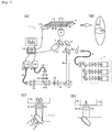
- the basic structure of the optical analysis device which realizes the inventive optical analysis technique may be a device formed by combining an optical system of a confocal microscope and a photodetector as schematically illustrated in Fig. 1 (A) , with which FCS, FIDA, etc. can be performed.
- the optical analysis device 1 consists of an optical system 2-17 and a computer 18 for acquiring and analyzing data together with controlling the operation of each part in the optical system.
- the optical system of the optical analysis device 1 may be the same as the optical system of a usual confocal microscope, where laser light emitted from a light source 2 and transmitted through the inside of a single mode fiber 3 (Ex) forms light diverging to be radiated at the angle decided by an inherent NA at the emitting end of the fiber; and after forming a parallel beam with a collimator 4, the light is reflected on a dichroic mirror 5 and reflective mirrors 6 and 7, entering into an objective 8.
- the objective 8 typically, there is placed a sample container or a micro plate 9 having wells 10 arranged thereon, to which one to several tens of ⁇ L of a sample solution is dispensed, and the laser light emitted from the objective 8 is focused in the sample solution in the sample container or well 10, forming a region having strong light intensity (excitation region).
- light-emitting particles to be observed objects which are fluorescent particles or particles to which a light emitting label such as a fluorescent dye is attached, are dispersed or dissolved, and when a light-emitting particle enters into the excitation region, the light-emitting particle during dwelling in the excitation region is excited, emitting light.
- a barrier filter 14 where light components only in a specific wavelength band region are selected
- the pinhole 13 is located at a conjugate position of the focal position of the objective 8, and thereby only the light emitted from the focal region of the laser light, i.e., the excitation region, as schematically shown in Fig. 1 (B) , passes through the pinhole 13 while the light from regions other than the excitation region is blocked.
- the focal region of the laser light illustrated in Fig. 1 (B) is a light detection region in this light analysis device, whose effective volume is usually about 1-10 fL (Typically, the light intensity is spread in accordance with a Gaussian distribution having the peak at the center of the region.
- the effective volume is a volume of an approximate ellipsoid bordering a surface where the light intensity reduced to 1/e 2 of the peak intensity.), which is called as "confocal volume".
- confocal volume since the light from one light-emitting particle, for example, the faint light from one fluorescent dye molecule, is detected in this invention, preferably, a super high sensitive photodetector, usable for the photon counting, is used for the photodetector 16.
- the measurement of light intensity is sequentially performed in the manner of measuring the number of photons arriving at the photodetector for every predetermined unit time (BIN TIME) in a predetermined term.
- BIN TIME predetermined unit time
- a mechanism for scanning the inside of the sample solution with the light detection region i.e., the focal region, namely for moving the position of the light detection region within the sample solution.
- the mechanism for moving the position of the light detection region for example, as schematically illustrated in Fig. 1 (C) , there may be employed a mirror deflector 17 which changes the direction of the reflective mirror 7 (Type of moving the absolute position of the light detection region).
- This mirror deflector 17 may be the same as that of a galvanomirror device equipped on a usual laser scan type microscope. Or, alternatively, as illustrated in Fig.
- a stage position changing apparatus 17a to move the horizontal position of the container 10 (micro plate 9) into which a sample solution has been dispensed for moving the relative position of the light detection region in the sample solution (Type of moving the absolute position of a sample solution). Even in either of the types, in order to attain a desired moving pattern of the position of the light detection region, the mirror deflector 17 or the stage position changing apparatus 17a is driven in harmony with the light detection of the photodetector 16 under the control of the computer 18.
- the movement track of the position of the light detection region may be arbitrarily selected from circular, elliptical, rectangular, straight and curvilinear ones, or a combination of these (In the program in the computer 18, it may be designed so that various moving patterns can be selected.).
- the position of the light detection region may be moved in the vertical direction by moving the objective 8 up and down.
- the above-mentioned optical system is used as a multiphoton microscope.
- the pinhole 13 may be removed.
- the optical system 2-5 for generating excitation light may be omitted.
- the above-mentioned optical system of the confocal microscope is used as it is.
- two or more excitation light sources 2 may be provided so that the wave length of the excitation light can be selected appropriately in accordance with the excitation wave length of the light-emitting particle.
- two or more photodetectors 16 may also be provided so that, when the sample contains two or more kinds of light-emitting particles whose wave lengths differ from one another, the respective lights from them can be detected separately in accordance with the wave lengths.
- Spectral analysis techniques such as FCS and FIDA
- FCS and FIDA are advantageous in that the required sample amount is extremely small and a test can be performed promptly as compared with the conventional biochemical analytical techniques.
- concentration and characteristics of a particle to be observed are principally computed based on the fluorescence intensity fluctuation, and therefore, in order to obtain accurate measurement results, the concentration or number density of the particle to be observed in a sample solution should be at a level where about one particle to be observed always exists in a light detection region CV during the fluorescence intensity measurement as schematically drawn in Fig. 8 (A) so that significant light intensity (photon count) can be always detected in the measuring term as shown in the right-hand side of the drawing.
- an optical analysis technique based on a new principle which enables the detection of characteristics, such as the number density or concentration of a particle to be observed, even when the concentration of the particle to be observed is lower than the level requested in the above-mentioned spectral analysis techniques, such as FCS and FIDA.
- the light detection is performed together with moving the position of the light detection region CV in a sample solution, namely, scanning the inside of the sample solution with the light detection region CV by driving the mechanism (mirror deflector 17 or stage position changing apparatus 17a) for moving the position of the light detection region as schematically drawn in Fig. 2 .
- the mechanism mirror deflector 17 or stage position changing apparatus 17a
- each significant light intensity i.e. each pulse form signal, appearing as illustrated in Fig. 2 (B) during the execution of the moving of the position of the light detection region CV and the light detection as described above
- the light-emitting particles are detected individually, and by counting the number thereof, the information about the number, concentration or number density of the light-emitting particles existing in the measured region can be acquired.
- noise the heat noise of a photodetector, background light
- a characteristic value of light intensity indicating the presence or absence of light from a single light-emitting particle is sequentially computed in every time section of a predetermined width in the time series light intensity data by means of the light intensity values (photon counts) in each time section.
- the characteristic value of the light intensity indicating the presence or absence of a light from a single light-emitting particle may be an arbitrary value which increases in the presence of a signal of light from a single light-emitting particle as compared with a case that no signal of light from a single light-emitting particle exist (when only noise exists), and for instance, the characteristic value may be the integrated value of the light intensity, the center value of the light intensity, the average value of the light intensity, the standard deviation of the light intensity (SD value), the variance of the light intensity, the entropy of the light intensity (EP value), the maximum value of the light intensity and the number of particles computed from the value of an autocorrelation function of the light intensity with the correlation time being set to 0, etc., in a time section of a predetermined width.
- SD value standard deviation of the light intensity
- EP value entropy of the light intensity
- the characteristic value may be a value selected from a group of a total value of photon counts, a center value of photon counts, an average value of photon counts, a standard deviation of photon counts, a variance of photon counts, an entropy of photon counts, a maximum value of photon counts and a the number of particles computed from an autocorrelation function value of photon counts with a correlation time being set to 0, in a time section of a predetermined width.
- the predetermined width of the time section for the computation of the above-mentioned characteristic value is set to be substantially longer than a time width required for an interval from a time of one light-emitting particle's entering into the light detection region to a time of its exiting therefrom, and also substantially shorter than a time width from a time of one light-emitting particle's entering into the light detection region to a time of a different light-emitting particle's entering into the light detection region.
- one time section in which a light signal of a light-emitting particle exists corresponds to an existence of one light-emitting particle, namely, the one to one relation between a time section and the existence of a light-emitting particle is established, and thereby the process in counting light-emitting particles becomes advantageously easy.
- the predetermined width of the time section is shorter than a time width required for an interval from a time of one light-emitting particle's entering into the light detection region to a time of its exiting therefrom, the light signal of one light-emitting particle would exist over two or more time sections, and thus, a process for making a plurality of time sections correspond to one light-emitting particle would be required.
- the predetermined width of the time section is longer than a time width from a time of one light-emitting particle's entering into the light detection region to a time of a different light-emitting particle's entering into the light detection region, the light signals of a plurality of light-emitting particles would exist in one time section, and thereby it becomes difficult to detect one light-emitting particle one by one.
- the upper limit ⁇ high of the predetermined width is to be a predetermined width in which the number of light-emitting particles included in each time section becomes substantially not more than one.
- the upper limit ⁇ high of the predetermined width can be determined in one of the following ways.
- the particle used as the object to be observed in the inventive optical analysis technique may be an arbitrary particle as long as it is dispersed and moving at random in a sample solution, such as a dissolved molecule, and the particle may be, for instance, a biological molecule, i.e. a protein, a peptide, a nucleic acid, a lipid, a sugar chain, an amino acid, etc. or an aggregate thereof, a virus, a cell, a metallic colloid or other non-biological molecule.
- a biological molecule i.e. a protein, a peptide, a nucleic acid, a lipid, a sugar chain, an amino acid, etc. or an aggregate thereof, a virus, a cell, a metallic colloid or other non-biological molecule.
- the particle used as the object to be observed is not a light-emitting particle
- a particle prepared by attaching a light emitting label (a fluorescence molecule, a phosphorescence molecule, a chemiluminescence or bioluminescent molecule) with the particle to be observed in an arbitrary way
- the sample solution is typically an aqueous solution, although not limited thereto and an organic solvent and other arbitrary liquid may be used.
- the measurement of the light intensity in the inventive optical analysis may be performed in the same manner as the measurement process of the light intensity in FCS or FIDA except driving the mirror deflector 17 or stage position changing apparatus 17a to move the position of the light detection region within the sample solution (to scan in the sample solution) during the measurement.
- the computer 18 executes programs memorized in a storage device (not shown)(the process of moving the position of the light detection region in the sample solution, and the process of detecting light from the light detection region during the moving of the position of the light detection region and generating time series light intensity data), and then illuminating the light detection region in the sample solution with the excitation light and measuring light intensity will be started.
- the moving speed of the position of the light detection region during the measurement of the light intensity may be a predetermined velocity set arbitrarily, for example, experimentally or in order to meet the purpose of an analysis.
- the region size or volume through which the light detection region has passed is required, and therefore, the moving of the position of the light detection region is performed in a manner enabling the grasping of the moving distance.
- the moving speed is constant, although not limited thereto.
- the moving speed of the position of the light detection region in order to perform quantitatively precisely individual detection of the light-emitting particles from the measured time series light intensity data or the counting of the number of the light-emitting particles, the moving speed is set to a value quicker than the moving speed in the random motion, i.e., Brownian motion of a light-emitting particle.
- the particle to be observed in the inventive optical analysis technique is a particle dispersed or dissolved in a solution and moving at random freely, its position moves with time owing to the Brownian motion.
- the moving speed of the position of the light detection region is slower than the movement of a particle owing to the Brownian motion, the particle moves at random in the region as schematically drawn in Fig.
- the moving speed of the position of the light detection region is set to be quicker than the average moving speed of a particle by the Brownian motion (diffusional moving velocity) so that a particle will cross the light detection region in an approximately straight line and thereby the profile of the change of the light intensity corresponding to each light-emitting particle becomes almost uniform in the time series light intensity data as illustrated in Fig. 4 (B) (When a light-emitting particle passes through the light detection region in an approximately straight line, the profile of the light intensity change is similar to the excitation light intensity distribution.) and the correspondence between each light-emitting particle and light intensity can be easily determined.
- the moving speed of the position of the light detection region may be set to a value sufficiently quicker than Vdif.
- Vdif will be 1.0x10 -3 m/s
- supposing Wo is about 0.62 ⁇ m
- the moving speed of the position of the light detection region may be set to its 10 times or more, e.g. 15 mm/s.
- an appropriate moving speed of the position of the light detection region may be determined by repeating the executions of a preliminary experiment with setting various moving speeds of the position of the light detection region in order to find the condition that the profile of a light intensity variation becomes an expected profile (typically, similar to the excitation light intensity distribution).
- an analysis of the light intensity as described below may be performed in the computer 18 through processes in accordance with programs memorized in a storage device (the process of computing a characteristic value of light intensity indicating the presence or absence of the light from a single light-emitting particle for every time section of a predetermined width in the time series light intensity data, and the process of detecting individually the light signal of each light-emitting particle based on the characteristic value of the light intensity for every time section of a predetermined width).
- the light intensity variation corresponding to the light-emitting particle in the time series light intensity data has a profile reflecting the light intensity distribution in the light detection region (determined by the optical system) (usually approximately bell shape) as schematically drawn in Fig. 4 (b) , which variation is significantly different from that of a period in the data in which period no light-emitting particle has passed (a condition that noise generates at random).
- a characteristic value of light intensity for every time section of a predetermined width in time series light intensity data is computed.
- the characteristic value of light intensity may be a value selected from a group of a total value of photon counts, a center value of photon counts, an average value of photon counts, a standard deviation of photon counts, a variance of photon counts, an entropy of photon counts, a maximum value of photon counts and the number of particles computed from an autocorrelation function value of photon counts with a correlation time being set to 0, in a time section of a predetermined width.
- the total value of photon counts is the total value of the photon counts in a time section of a predetermined width. Since the total value in a time section where a light signal of a light-emitting particle exists increases by the number of photons from the light-emitting particle from the total value in the other time sections, it can be judged that a light signal of a light-emitting particle exists in a certain time section when the magnitude of the total value of the certain time section is larger than a predetermined threshold value.
- the center value and the maximum value of photon counts each are the center value and the maximum value of the photon counts found in a time section of a predetermined width. Since a photon count during a period when the light of a light-emitting particle has arrived at a photodetector becomes larger than in a case that only usual noises occur, the center value and the maximum value also increase in a time section where a light signal of a light-emitting particle exists. Thus, it can be judged that a light signal of a light-emitting particle exists in a certain time section when the magnitude of the center value or the maximum value in the certain time sections is larger than a predetermined threshold value.
- the average value of photon counts is the time average value of the photon counts in a time section of a predetermined width.
- the time average value of photon counts in the time section of the predetermined width also increases.
- the standard deviation value, variance value and entropy value of photon counts each are the standard deviation value and variance value in the time average, and the entropy of information content of photon counts in a time section of a predetermined width, and these each are a characteristic value indicating the degree of the dispersion of the temporal variation of the photon count found within a time section of a predetermined width.
- the entropy value of photon counts when the probability that the photon count is x at a certain time (BIN TIME) is px, using the number of the time points ix at which the photon count is x, in a certain time section, the entropy value of photon counts is the value given by: ⁇ log 2 p 0 i 0 ⁇ p 1 i 1 ⁇ ... ⁇ px ix ⁇ ... ⁇ pn in Usually, the probability px that the photon count is x satisfies p0>p1>p2>...>px...>pn.
- the entropy value in a section where only noise exists is approximately -log 2 (p0 i0 ⁇ p1 i1. p2 i2 ), it becomes -log 2 (p0 i0 ⁇ p1 i1 -p2 i2 -p3 i3 -p4 i4 ), etc., in a section where a light signal of a light-emitting particle exists, and thus, the value increases.
- the the number of particles in a time section of a predetermined width, computed from an autocorrelation function value of photon counts with a correlation time being set to 0, is the quantity equivalent to the number of particles in the time section.
- this number of particles is the number of particles found in each time section, it can be judged that a light signal of a light-emitting particle exists in a time section when the number of particles is larger than a predetermined threshold value, similarly to the above-mentioned characteristic values.
- one light-emitting particle corresponds to one time section judged as a time section in which a light signal of a light-emitting particle exists, and therefore, the number of light-emitting particles is determined by counting the number of these time sections.
- the number density or concentration of the light-emitting particle can be determined using the volume of the whole region which the light detection region has passed through.
- the effective volume of the light detection region varies depending on the wave length of excitation light or detected light, the numerical aperture of lenses and the adjustment condition of the optical system, and therefore, it is difficult to compute the effective volume of the light detection region from the design parameter values.
- the light intensity measurement, the detection of light-emitting particles and the counting thereof are performed as explained above with a solution having a known light-emitting particle concentration (reference solution) under the same condition as that for the measurement of the sample solution to be tested, and then, from the detected number of light-emitting particles and the concentration of light-emitting particle in the reference solution, the volume of the whole region which the light detection region has passed through, i.e., the relation between the detected number and the concentration of the light-emitting particle, may be determined.
- the light-emitting particle of a reference solution may be a light emitting label (fluorescent dye etc.) having the same wavelength characteristic as a particle to be observed.
- Vt N / C
- the plurality of solutions of different concentrations of a light-emitting particle are prepared as reference solutions and the measurement is performed for each of the solutions, and then, the average value of the computed Vt is determined as the volume Vt of the whole region which the light detection region has passed through.
- the volume of the light detection region and the volume of the whole region which the light detection region has passed through may be given by an arbitrary method, for instance, using FCS and FIDA, instead of the above-mentioned method.
- the optical analysis device of this embodiment there may be previously memorized in a storage apparatus of the computer 18 the information on the relations (expression (9)) between concentrations C and light-emitting particle numbers N of various standard light-emitting particles for assumed moving patterns of the light detection region, so that a user of the device can appropriately use the memorized information on the relation in conducting an optical analysis.
- inventive optical analysis technique by moving, in a sample solution, the position of a micro region, i.e. a light detection region, namely scanning the inside of the sample solution and detecting individually a light-emitting particle crossing the light detection region or conducting the counting of the light-emitting particles, where no statistical procedures, such as calculation of fluorescence intensity fluctuation, performed in FCS, FIDA, etc., are included, it becomes possible to detect a condition or a characteristic of a particle to be observed in a sample solution whose the concentration or number density of the particle to be observed is lower than the level used in FCS, FIDA, etc.
- the inventive optical analysis technique basically uses the same optical system as FCS, FIDA, etc. it may be performed together with FCS, FIDA, etc.
- FCS optical analysis technique
- the concentration difference between substances is large, for example when the concentration of one substance is nM order and that of the other substance is pM order
- FCS or FIDA for the substance of the higher concentration
- measurement and analysis technique for the substance of the lower concentration.
- the concentration range of a light-emitting particle in a sample solution which can be measured by the present invention was verified using a fluorescent dye, ATTO633 (sigma Aldrich Cat. No. 18620) as the light-emitting particle.
- a fluorescent dye ATTO633 (sigma Aldrich Cat. No. 18620) as the light-emitting particle.
- phosphate buffers including 0.05% Tween20
- 10 fM, 100 fM, 1 pM, 10 pM, 100 pM, and 1 nM were prepared, respectively.
- a single molecule fluorescence measuring apparatus MF20 (Olympus Corporation), equipped with the optical system of a confocal fluorescence microscope and a photon counting system was used as the optical analysis device, and time series light intensity data were acquired for the above-mentioned respective sample solutions in accordance with the manner explained in the above-mentioned "(1) Measurement of the light intensity of a sample solution".
- the photodetector 16 a super high sensitive photodetector capable of detecting an arrival of a single photon was used, and thereby the light detection was the photon counting performed sequentially for a predetermined term in a manner that the number of photons arriving at the photodetector in every predetermined unit time (BIN TIME) was measured. Accordingly, the time series light intensity data is time series photon count data. Further, a 633 nm laser light was used for excitation light, and the detected light wavelength was set from 660 to 710 nm using a band pass filter. Measurement for 2 seconds was performed 3 times, where the moving speed of the position of the light detection region in the sample solution was set to 15 mm / second and BIN TIME was set to 10 ⁇ sec.
- Fig. 5 (A) shows an example of the whole time series photon count data obtained by a measurement for 2 seconds
- Fig. 5 (B) shows an enlarged diagram of a part of the time series photon count data of the measurement for 2 seconds.
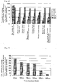
- Fig. 6 shows the number of the time sections having the respective characteristic values exceeding beyond the corresponding predetermined threshold values, for each of the above-mentioned solutions.
- the threshold value of each characteristic value was set as follows.
- each of the illustrated characteristic values increased with the increase of the light-emitting particle concentration in the sample solution.
- the number of particles computed from the autocorrelation function value of the photon counts with the correlation time being set to 0 no remarkable change was seen with light-emitting particle concentration of less than 1 pM.
- the binarized domain number no remarkable concentration dependency were obtained for the sample solutions used for the measurement.
- the above-mentioned results suggest that the light from a light-emitting particle is detected individually and its concentration can be determined by referring to a characteristic value of light intensity indicating the presence or absence of light from a single light-emitting particle computed for every time section of a predetermined width in the time series light intensity data obtained by measuring light in accordance with the present invention.
- Fig. 7 shows the detected number of the light-emitting particles (the number of the time sections where a characteristic value exceeded the predetermined threshold value) in changing the width of the time section in computing a characteristic value (the total value of photon counts) in the time series photon count data of the sample solution of the light-emitting particle concentration of 10 pM.
- the time section width was 100 to 200 ⁇ sec., the detected number of the light-emitting particles was stabilized.
- the time section width was less than 100 ⁇ sec.
- the detected number of particles increased apparently. Since the time required for a single light-emitting particle to pass through the light detection region linearly was computed as about 74 ⁇ sec. in the condition of the measurement of this experimental example, it is considered that the number of times that one light-emitting particle was detected over two or more time sections was reduced by making the time section width longer than the time required for a single light-emitting particle to pass through the light detection region linearly. Moreover, in the above results, when the time section width exceeded beyond 200 ⁇ sec., the detected number of particles was reduced apparently.
- the upper limit ⁇ high of the predetermined width of the time section computed using the expression (2d) with the allowable error being about 5%, was about 200 ⁇ sec. (the radius Wo of the light detection region was set to be ⁇ 1 ⁇ m.).
- one light-emitting particle can be made to correspond to one time section by setting the width of the time section substantially longer than a time width required for an interval from a time of one light-emitting particle's entering into the light detection region to a time of its exiting therefrom, and also substantially shorter than a time width from a time of one light-emitting particle's entering into the light detection region to a time of a different light-emitting particle's entering into the light detection region.
- the number density or concentration of a light-emitting particle can be determined in the concentration range lower than the limit of the number density or concentration measurable by conventional methods using fluorescence intensity.
- the lower limit of particle concentration measurable in optical analysis techniques such as FCS, FIDA, and PCH, including statistical procedures, e.g. calculation of fluorescence intensity fluctuation was about 1 nM
- the lower limit of the particle concentration measurable in the present embodiment was -10 fM
- the measurement is possible for a particle in the range of a concentration significantly lower than the case of the optical analysis techniques such as FCS, FIDA and PCH.
Landscapes
- Chemical & Material Sciences (AREA)
- Physics & Mathematics (AREA)
- Health & Medical Sciences (AREA)
- General Physics & Mathematics (AREA)
- Analytical Chemistry (AREA)
- Life Sciences & Earth Sciences (AREA)
- Biochemistry (AREA)
- General Health & Medical Sciences (AREA)
- Immunology (AREA)
- Pathology (AREA)
- Nuclear Medicine, Radiotherapy & Molecular Imaging (AREA)
- Optics & Photonics (AREA)
- Dispersion Chemistry (AREA)
- Investigating, Analyzing Materials By Fluorescence Or Luminescence (AREA)
- Investigating Or Analysing Materials By The Use Of Chemical Reactions (AREA)
Claims (11)
- Dispositif d'analyse optique (1) configuré pour détecter de la lumière provenant d'une particule d'émission de lumière qui est dispersée et se déplace de manière aléatoire dans une solution d'échantillon, le dispositif (1) comprenant :un microscope confocal ou un microscope multiphotonique, le dispositif d'analyse optique (1) étant configuré pour détecter la lumière à l'aide d'un système optique (2 - 17) du microscope confocal ou du microscope multiphotonique ;une partie de déplacement de région de détection de lumière (7, 17) configurée pour déplacer une position d'une région de détection de lumière (CV) du système optique (2 - 17) dans la solution d'échantillon ;une partie de détection de lumière (16) configurée pour détecter de la lumière provenant de la région de détection de lumière (CV) ; etune partie de traitement de signal (18) configurée pour générer des données d'intensité lumineuse en série temporelle de la lumière provenant de la région de détection de lumière (CV) détectée avec la partie de détection de lumière (16) pendant le déplacement de la position de la région de détection de lumière (CV) dans la solution d'échantillon, et pour détecter de manière individuelle un signal lumineux, provenant de chaque particule d'émission de lumière dans les données d'intensité lumineuse en série temporelle ;la partie de traitement de signal (18) étant configurée pour calculer une valeur caractéristique de l'intensité lumineuse, indiquant une présence ou une absence de la lumière provenant d'une unique particule d'émission de lumière dans toutes les sections temporelles d'une largeur prédéterminée dans les données d'intensité lumineuse en série temporelle, et pour évaluer de manière individuelle si le signal lumineux provenant de la particule d'émission de lumière existe dans la section temporelle de la largeur prédéterminée, en utilisant la valeur caractéristique,caractérisé par le fait quela partie de déplacement (7, 17) de région de détection de lumière (CV) est configurée pour déplacer la position de la région de détection de lumière (CV) à une vitesse plus rapide qu'une vitesse de déplacement de diffusion de la particule d'émission de lumière, etla largeur prédéterminée est définie pour être sensiblement plus longue qu'une largeur temporelle requise pour un intervalle d'un instant d'entrée d'une particule d'émission de lumière dans la région de détection de lumière (CV) à un instant de sortie de celle-ci, et également sensiblement plus courte qu'une largeur temporelle d'un instant d'entrée d'une particule d'émission de lumière dans la région de détection de lumière (CV) à un instant d'entrée d'une particule d'émission de lumière différente dans la région de détection de lumière (CV).
- Dispositif (1) selon la revendication 1,
caractérisé par le fait que la partie de traitement de signal (18) est configurée pour compter le nombre de la(les) particule(s) d'émission de lumière détectée(s) pendant le déplacement de position de la région de détection de lumière (CV) par comptage du nombre de la(des) section(s) temporelle(s) de la largeur prédéterminée ayant un signal lumineux provenant d'une particule d'émission de lumière. - Dispositif (1) selon la revendication 1 ou 2,
caractérisé par le fait que la partie de détection de lumière (16) est configurée pour détecter la lumière provenant de la région de détection de lumière (CV) par comptage de photons, et les données d'intensité lumineuse en série temporelle sont des données de compte de photons en série temporelle. - Dispositif (1) selon l'une quelconque des revendications 1 à 3,
caractérisé par le fait que la valeur caractéristique de l'intensité lumineuse dans la section temporelle de la largeur prédéterminée dans laquelle de la lumière provenant d'une unique particule d'émission de lumière existe est plus grande que la valeur caractéristique de l'intensité lumineuse dans la section temporelle de la largeur prédéterminée dans laquelle aucune lumière provenant d'une unique particule d'émission de lumière n'existe, et il est déterminé que le signal lumineux provenant de la particule d'émission de lumière existe dans la section temporelle de la largeur prédéterminée lorsque la valeur caractéristique de l'intensité lumineuse est plus grande qu'une valeur de seuil prédéterminée. - Dispositif (1) selon la revendication 3,
caractérisé par le fait que la valeur caractéristique de l'intensité lumineuse est une valeur choisie parmi un groupe d'une valeur totale de comptes de photons, d'une valeur centrale de comptes de photons, d'une valeur moyenne de comptes de photons, d'un écart-type de comptes de photons, d'une variance de comptes de photons, d'une entropie de comptes de photons, d'une valeur maximale de comptes de photons, et du nombre de particules calculé à partir d'une valeur de fonction d'autocorrélation de comptes de photons avec un temps de corrélation qui est défini à 0, dans la section temporelle de la largeur prédéterminée. - Procédé d'analyse optique de détection de lumière provenant d'une particule d'émission de lumière qui est dispersée et se déplace de manière aléatoire dans une solution d'échantillon à l'aide d'un système optique (2 - 17) d'un microscope confocal ou d'un microscope multiphotonique, comprenant les étapes :déplacer une position d'une région de détection de lumière (CV) du système optique (2 - 17) dans la solution d'échantillon ;détecter de la lumière provenant de la région de détection de lumière (CV) tout en déplaçant la position de la région de détection de lumière (CV) dans la solution d'échantillon et générer des données d'intensité lumineuse en série temporelle ;calculer une valeur caractéristique d'intensité lumineuse indiquant une présence ou une absence de lumière provenant d'une unique particule d'émission de lumière dans toutes les sections temporelles d'une largeur prédéterminée dans les données d'intensité lumineuse en série temporelle ; etdéterminer de manière individuelle si le signal lumineux provenant de la particule d'émission de lumière existe dans la section temporelle de la largeur prédéterminée, à l'aide de la valeur caractéristique de l'intensité lumineuse dans la ou chacune des sections temporelles de la largeur prédéterminée,caractérisé par le fait quedans l'étape de déplacement de la position de la région de détection de lumière (CV), la position de la région de détection de lumière (CV) est déplacée à une vitesse supérieure à une vitesse de déplacement de diffusion de la particule d'émission de lumière, etla largeur prédéterminée est définie pour être sensiblement plus longue qu'une largeur temporelle requise pour un intervalle d'un instant d'entrée d'une particule d'émission de lumière dans la région de détection de lumière (CV) à un instant de sortie de celle-ci, et également sensiblement plus courte qu'une largeur temporelle d'un instant d'entrée d'une particule d'émission de lumière dans la région de détection de lumière (CV) à un instant d'entrée d'une particule d'émission de lumière différente dans la région de détection de lumière (CV).
- Procédé selon la revendication 6,
caractérisé par le fait qu'il comprend en outre une étape de comptage du nombre de la(les) particule(s) d'émission de lumière détectée(s) pendant le déplacement de la position de la région de détection de lumière (CV) par comptage du nombre des sections temporelles de la largeur prédéterminée ayant un signal lumineux provenant d'une particule d'émission de lumière. - Procédé selon la revendication 6 ou 7,
caractérisé par le fait que, dans l'étape de détection de lumière provenant de la région de détection de lumière (CV) et de génération de données d'intensité lumineuse en série temporelle, la lumière à partir de la région de détection de lumière (CV) est détectée par comptage de photons, et les données d'intensité lumineuse en série temporelle sont des données de compte de photons en série temporelle. - Procédé selon l'une quelconque des revendications 6 à 8,
caractérisé par le fait que la valeur caractéristique de l'intensité lumineuse dans la section temporelle de la largeur prédéterminée dans laquelle de la lumière provenant d'une unique particule d'émission de lumière existe est plus grande qu'une valeur caractéristique de l'intensité lumineuse dans la section temporelle de la largeur prédéterminée dans laquelle aucune lumière provenant d'une unique particule d'émission de lumière n'existe, et il est déterminé que le signal lumineux provenant de la particule d'émission de lumière existe dans la section temporelle de la largeur prédéterminée lorsque la valeur caractéristique de l'intensité lumineuse et plus grande qu'une valeur de seuil prédéterminée. - Procédé selon la revendication 8,
caractérisé par le fait que la valeur caractéristique de l'intensité lumineuse est une valeur choisie parmi un groupe d'une valeur totale de comptes de photons, d'une valeur centrale de comptes de photons, d'une valeur moyenne de comptes de photons, d'un écart-type de comptes de photons, d'une variance de comptes de photons, d'une entropie de comptes de photons, d'une valeur maximale de comptes de photons, et du nombre de particules calculé à partir d'une valeur de fonction d'autocorrélation de comptes de photons avec un temps de corrélation qui est défini à 0, dans la section temporelle de la largeur prédéterminée. - Programme d'ordinateur pour une analyse optique pour la détection de lumière provenant d'une particule d'émission de lumière qui est dispersée et se déplace de manière aléatoire dans une solution d'échantillon à l'aide d'un système optique (2 - 17) d'un microscope confocal ou d'un microscope multiphotonique, le programme d'ordinateur étant configuré pour commander un ordinateur pour exécuter les étapes :commander une partie de déplacement de région de détection de lumière (7, 17) pour déplacer une position d'une région de détection de lumière (CV) du système optique (2 - 17) dans la solution d'échantillon ;commander une partie de détection de lumière (16) pour détecter de la lumière provenant de la région de détection de lumière (CV) tout en déplaçant la position de la région de détection de lumière (CV) dans la solution d'échantillon et générer des données d'intensité lumineuse en série temporelle ;calculer une valeur caractéristique d'intensité lumineuse indiquant une présence ou une absence de la lumière provenant d'une unique particule d'émission de lumière dans toutes les sections temporelles d'une largeur prédéterminée dans les données d'intensité lumineuse en série temporelle ; etdéterminer de manière individuelle si le signal lumineux provenant de la particule d'émission de lumière existe dans la section temporelle de la largeur prédéterminée, à l'aide de la valeur caractéristique,dans l'étape de déplacement de la position de la région de détection de lumière (CV), la position de la région de détection de lumière (CV) est déplacée à une vitesse supérieure à une vitesse de déplacement de diffusion de la particule d'émission de lumière, etla largeur prédéterminée est définie pour être sensiblement plus longue qu'une largeur temporelle requise pour un intervalle d'un instant d'entrée d'une particule d'émission de lumière dans la région de détection de lumière (CV) à un instant de sortie de celle-ci, et également sensiblement plus courte qu'une largeur temporelle d'un instant d'entrée d'une particule d'émission de lumière dans la région de détection de lumière (CV) à un instant d'entrée d'une particule d'émission de lumière différente dans la région de détection de lumière (CV).
Applications Claiming Priority (2)
| Application Number | Priority Date | Filing Date | Title |
|---|---|---|---|
| JP2010044714 | 2010-03-01 | ||
| PCT/JP2011/053483 WO2011108371A1 (fr) | 2010-03-01 | 2011-02-18 | Dispositif d'analyse optique, procédé d'analyse optique, et programme informatique d'analyse optique |
Publications (3)
| Publication Number | Publication Date |
|---|---|
| EP2543990A1 EP2543990A1 (fr) | 2013-01-09 |
| EP2543990A4 EP2543990A4 (fr) | 2017-11-01 |
| EP2543990B1 true EP2543990B1 (fr) | 2019-06-26 |
Family
ID=44542030
Family Applications (3)
| Application Number | Title | Priority Date | Filing Date |
|---|---|---|---|
| EP11750483.7A Active EP2543990B1 (fr) | 2010-03-01 | 2011-02-18 | Dispositif d'analyse optique, procédé d'analyse optique, et programme informatique d'analyse optique |
| EP11750482.9A Withdrawn EP2543989A4 (fr) | 2010-03-01 | 2011-02-18 | Dispositif d'analyse optique, procédé d'analyse optique et programme informatique d'analyse optique |
| EP11750481.1A Not-in-force EP2522988B1 (fr) | 2010-03-01 | 2011-02-18 | Dispositif d'analyse optique, procédé d'analyse optique et programme informatique d'analyse optique |
Family Applications After (2)
| Application Number | Title | Priority Date | Filing Date |
|---|---|---|---|
| EP11750482.9A Withdrawn EP2543989A4 (fr) | 2010-03-01 | 2011-02-18 | Dispositif d'analyse optique, procédé d'analyse optique et programme informatique d'analyse optique |
| EP11750481.1A Not-in-force EP2522988B1 (fr) | 2010-03-01 | 2011-02-18 | Dispositif d'analyse optique, procédé d'analyse optique et programme informatique d'analyse optique |
Country Status (5)
| Country | Link |
|---|---|
| US (3) | US8710413B2 (fr) |
| EP (3) | EP2543990B1 (fr) |
| JP (4) | JP5802653B2 (fr) |
| CN (3) | CN102869982B (fr) |
| WO (3) | WO2011108369A1 (fr) |
Families Citing this family (62)
| Publication number | Priority date | Publication date | Assignee | Title |
|---|---|---|---|---|
| WO2007032940A2 (fr) * | 2005-09-12 | 2007-03-22 | Rutgers, The State University Of New Jersey Office Of Corporate Liaison And Technology Transfer | Système et procédé de génération d’images tridimensionnelles à partir d’images bioluminescentes bidimensionnelles, et de visualisation de formes et d’emplacements de tumeurs |
| US8798338B2 (en) * | 2006-01-09 | 2014-08-05 | University Of Wyoming | Method and system for counting particles in a laminar flow with an imaging device |
| EP2543990B1 (fr) * | 2010-03-01 | 2019-06-26 | Olympus Corporation | Dispositif d'analyse optique, procédé d'analyse optique, et programme informatique d'analyse optique |
| WO2012014778A1 (fr) * | 2010-07-26 | 2012-02-02 | オリンパス株式会社 | Procédé de détection de particules diluées dans une solution en utilisant une sonde luminescente |
| WO2012032981A1 (fr) | 2010-09-10 | 2012-03-15 | オリンパス株式会社 | Procédé d'analyse optique utilisant l'intensité optique d'une seule particule électroluminescente |
| CN103221806B (zh) | 2010-09-10 | 2015-11-25 | 奥林巴斯株式会社 | 使用两个以上的波长带的光的测量的光学分析方法 |
| EP2620762B1 (fr) * | 2010-09-21 | 2017-02-01 | Olympus Corporation | Méthode d'analyse optique par détection d'une particule luminescente unique |
| WO2012050011A1 (fr) * | 2010-10-13 | 2012-04-19 | オリンパス株式会社 | Procédé pour mesurer une valeur de caractéristique de diffusion de particule par détection d'une particule émettrice de lumière unique |
| CN103210302B (zh) | 2010-10-19 | 2015-05-27 | 奥林巴斯株式会社 | 观测单个发光粒子的偏振特性的光分析装置、光分析方法 |
| WO2012070414A1 (fr) | 2010-11-25 | 2012-05-31 | オリンパス株式会社 | Dispositif d'analyse photométrique et procédé d'analyse photométrique utilisant la caractéristique de longueur d'onde de lumière émise depuis une seule particule lumineuse |
| WO2012099234A1 (fr) * | 2011-01-20 | 2012-07-26 | オリンパス株式会社 | Procédé de photoanalyse et dispositif associé faisant appel à la détection de la lumière émise par une particule luminescente individuelle |
| EP2669376B1 (fr) | 2011-01-26 | 2017-08-16 | Olympus Corporation | Procédé pour identifier le polymorphisme d'une molécule d'acide nucléique |
| JP5856984B2 (ja) | 2011-01-26 | 2016-02-10 | オリンパス株式会社 | 核酸分子の多型識別方法 |
| JP5904996B2 (ja) * | 2011-03-29 | 2016-04-20 | オリンパス株式会社 | 単一発光粒子検出を用いた光分析装置、光分析方法並びに光分析用コンピュータプログラム |
| EP2706346A4 (fr) | 2011-04-13 | 2014-11-19 | Olympus Corp | Dispositif de photo-analyse utilisant une détection de particule émettrice de lumière unique, procédé pour photo-analyse et programme informatique pour photo-analyse |
| EP2700935A4 (fr) * | 2011-04-18 | 2014-10-22 | Olympus Corp | Procédé de détermination quantitative de particules cibles, dispositif d'analyse photométrique et programme informatique d'analyse photométrique |
| EP2700934B1 (fr) * | 2011-04-20 | 2016-12-14 | Olympus Corporation | Procédé de détection d'une molécule d'acide nucléique dans un échantillon biologique |
| WO2013002261A1 (fr) * | 2011-06-27 | 2013-01-03 | オリンパス株式会社 | Procédé de détection de particules cibles |
| EP2743682B1 (fr) * | 2011-08-11 | 2017-05-31 | Olympus Corporation | Procédé de détection de particules cibles |
| EP2743684B1 (fr) * | 2011-08-12 | 2017-09-06 | Olympus Corporation | Procédé de détection de particules fluorescentes |
| EP2746748B1 (fr) | 2011-08-15 | 2017-12-06 | Olympus Corporation | Dispositif d'analyse photométrique par détection de particules électroluminescentes individuelles, procédé et programme d'ordinateur afférents |
| CN103765196B (zh) | 2011-08-26 | 2016-03-02 | 奥林巴斯株式会社 | 利用单个发光粒子检测的光分析装置及光分析方法 |
| CN103765195B (zh) * | 2011-08-26 | 2018-06-01 | 奥林巴斯株式会社 | 利用光分析的单个粒子检测装置、单个粒子检测方法以及单个粒子检测用计算机程序 |
| JP6010034B2 (ja) | 2011-08-30 | 2016-10-19 | オリンパス株式会社 | 標的粒子の検出方法 |
| JP6010035B2 (ja) * | 2011-08-30 | 2016-10-19 | オリンパス株式会社 | 単一発光粒子検出を用いた光分析装置、光分析方法及び光分析用コンピュータプログラム |
| WO2013069504A1 (fr) | 2011-11-10 | 2013-05-16 | オリンパス株式会社 | Dispositif de spectroscopie, procédé de spectroscopie et programme d'ordinateur pour spectroscopie, utilisant une détection de particule électroluminescente individuelle |
| JP2015083922A (ja) * | 2012-02-07 | 2015-04-30 | オリンパス株式会社 | 光分析を用いた単一粒子検出装置、単一粒子検出方法及び単一粒子検出用コンピュータプログラム |
| CN104115001B (zh) * | 2012-02-17 | 2016-08-24 | 奥林巴斯株式会社 | 利用单个粒子检测的光分析装置、光分析方法 |
| CN104115003B (zh) | 2012-02-22 | 2016-03-23 | 奥林巴斯株式会社 | 目标粒子的检测方法 |
| JP6095645B2 (ja) * | 2012-03-21 | 2017-03-15 | オリンパス株式会社 | 標的核酸分子の検出方法 |
| JP5940651B2 (ja) | 2012-04-18 | 2016-06-29 | オリンパス株式会社 | 標的粒子の検出方法 |
| WO2013157319A1 (fr) | 2012-04-18 | 2013-10-24 | オリンパス株式会社 | Dispositif de détection de particules uniques utilisant la photo-analyse, procédé de détection de particules uniques et programme informatique de détection de particules uniques |
| JP2013238479A (ja) * | 2012-05-15 | 2013-11-28 | Seiko Epson Corp | 検出装置 |
| CN104508462B (zh) | 2012-08-02 | 2018-04-24 | 奥林巴斯株式会社 | 使用共焦显微镜或多光子显微镜的光学系统的光分析装置、光分析方法以及光分析用计算机程序 |
| CN104736999B (zh) * | 2012-10-25 | 2017-04-12 | 奥林巴斯株式会社 | 目标粒子的检测方法 |
| WO2014141516A1 (fr) | 2013-03-13 | 2014-09-18 | オリンパス株式会社 | Procédé d'évaluation d'un dispositif d'analyse de lumière et échantillon fantôme |
| EP3029505A4 (fr) * | 2013-07-31 | 2017-03-15 | Olympus Corporation | Dispositif de microscope optique, procédé de microscopie et programme informatique pour microscopie faisant appel à la technologie de détection de particule électroluminescente unique |
| KR102126032B1 (ko) * | 2013-07-31 | 2020-07-08 | 삼성전자주식회사 | 다채널 형광 검출 모듈 및 이를 포함하는 핵산 분석 시스템 |
| DE102013015016A1 (de) * | 2013-09-07 | 2014-09-18 | Testo Ag | Verfahren zur Partikeldetektion in einem partikelhaltigen Fluid und korrespondierende Partikeldetektionsvorrichtung |
| JP6313776B2 (ja) | 2013-10-07 | 2018-04-18 | オリンパス株式会社 | 単一発光粒子検出を用いた光分析装置、光分析方法及び光分析用コンピュータプログラム |
| JP6593668B2 (ja) * | 2014-07-11 | 2019-10-23 | 株式会社リコー | 微粒子分散性評価装置 |
| WO2016017591A1 (fr) * | 2014-08-01 | 2016-02-04 | シャープ株式会社 | Instrument de test, dispositif de test, kit de test, et procédé de mesure |
| WO2016125278A1 (fr) * | 2015-02-05 | 2016-08-11 | オリンパス株式会社 | Dispositif d'analyse optique utilisant une seule détection de particules électroluminescentes |
| WO2017098597A1 (fr) | 2015-12-09 | 2017-06-15 | オリンパス株式会社 | Procédé d'analyse optique et dispositif d'analyse optique utilisant une détection de particule électroluminescente unique |
| DE112016005953T5 (de) * | 2015-12-25 | 2018-10-04 | Keyence Corporation | Konfokaler verschiebungssensor |
| CA3011719A1 (fr) | 2016-01-21 | 2017-07-27 | Protein Dynamic Solutions Llc | Procede et systeme permettant une analyse de donnees spectrales |
| JP6793352B2 (ja) * | 2016-03-31 | 2020-12-02 | パナソニックIpマネジメント株式会社 | 光源と、光検出器と、制御回路とを備える撮像装置 |
| WO2017199757A1 (fr) * | 2016-05-16 | 2017-11-23 | ソニー株式会社 | Dispositif optique et procédé de traitement d'informations |
| JP6249049B2 (ja) * | 2016-06-14 | 2017-12-20 | ソニー株式会社 | 微小粒子測定装置 |
| WO2018105462A1 (fr) * | 2016-12-08 | 2018-06-14 | 東京エレクトロン株式会社 | Procédé et programme de traitement de signaux |
| CN110312922B (zh) * | 2017-02-16 | 2023-11-03 | 皇家飞利浦有限公司 | 粒子表征装置和方法 |
| JP7207294B2 (ja) * | 2017-03-14 | 2023-01-18 | 凸版印刷株式会社 | 解析デバイス、解析キット、及び解析システム |
| WO2018179078A1 (fr) | 2017-03-28 | 2018-10-04 | オリンパス株式会社 | Dispositif d'analyse photométrique, procédé d'analyse photométrique et programme |
| DE102017128773A1 (de) * | 2017-12-04 | 2019-06-06 | Leica Microsystems Cms Gmbh | Detektoranordnung für die Mikroskopie |
| US11828905B2 (en) * | 2018-01-26 | 2023-11-28 | Institute Of Atmospheric Physics, Chinese Academy Of Sciences | Dual line diode array device and measurement method and measurement device for particle velocity |
| EP3752815B1 (fr) * | 2018-02-16 | 2026-04-01 | The Regents of the University of California | Systèmes, dispositifs, et procédés d'imagerie tridimensionnelle de particules mobiles |
| JP7489968B2 (ja) | 2018-09-14 | 2024-05-24 | ザ リージェンツ オブ ザ ユニバーシティ オブ カリフォルニア | 細胞選別装置及び方法 |
| EP3910315B1 (fr) * | 2019-01-09 | 2025-04-16 | Hitachi High-Tech Science Corporation | Dispositif de mesure de distribution de taille et procédé de mesure de distribution de taille |
| US12059520B2 (en) * | 2019-04-08 | 2024-08-13 | Baxter International Inc. | Priming sensor for a medical fluid delivery system |
| IT202000006031A1 (it) * | 2020-03-20 | 2021-09-20 | Celldynamics I S R L | Dispositivo fluidico per analisi di corpuscoli e relativo metodo |
| DE102022121505A1 (de) * | 2022-08-25 | 2024-03-07 | Carl Zeiss Meditec Ag | Verfahren, Computerprogramm und Datenverarbeitungseinheit zur Vorbereitung der Beobachtung einer Fluoreszenzintensität, Verfahren zum Beobachten einer Fluoreszenzintensität und optisches Beobachtungssystem |
| CN118980671A (zh) * | 2024-09-09 | 2024-11-19 | 上海交通大学 | 溶液中目标物的检测方法及装置、电子设备 |
Family Cites Families (34)
| Publication number | Priority date | Publication date | Assignee | Title |
|---|---|---|---|---|
| US4251733A (en) * | 1978-06-29 | 1981-02-17 | Hirleman Jr Edwin D | Technique for simultaneous particle size and velocity measurement |
| JPS63147419A (ja) | 1986-12-11 | 1988-06-20 | 松下電器産業株式会社 | 電気湯沸し器 |
| US4979824A (en) * | 1989-05-26 | 1990-12-25 | Board Of Trustees Of The Leland Stanford Junior University | High sensitivity fluorescent single particle and single molecule detection apparatus and method |
| JPH04337446A (ja) | 1991-05-15 | 1992-11-25 | Hitachi Ltd | 微粒子計測方法、定量方法および微粒子計測装置 |
| EP0836090A1 (fr) | 1996-10-12 | 1998-04-15 | Evotec BioSystems GmbH | Procédé d'analyse d'échantillons par détermination de la distribution de la clarité des particules |
| US6388788B1 (en) | 1998-03-16 | 2002-05-14 | Praelux, Inc. | Method and apparatus for screening chemical compounds |
| US20030036855A1 (en) | 1998-03-16 | 2003-02-20 | Praelux Incorporated, A Corporation Of New Jersey | Method and apparatus for screening chemical compounds |
| KR100560588B1 (ko) * | 1998-03-16 | 2006-03-16 | 에머샘 바이오사이언시즈 코프 | 공초점 마이크로스코피 영상 시스템 |
| JP3559525B2 (ja) * | 1999-04-29 | 2004-09-02 | エボテック オーアーイー アクチェンゲゼルシャフト | 生成関数を用いて蛍光分子又は他の粒子を特徴付ける方法 |
| US6376843B1 (en) | 1999-06-23 | 2002-04-23 | Evotec Oai Ag | Method of characterizing fluorescent molecules or other particles using generating functions |
| US8264680B2 (en) | 1999-05-28 | 2012-09-11 | Yokogawa Electric Corporation | Biochip reader and electrophoresis system |
| US6965113B2 (en) | 2000-02-10 | 2005-11-15 | Evotec Ag | Fluorescence intensity multiple distributions analysis: concurrent determination of diffusion times and molecular brightness |
| US20010035954A1 (en) * | 2000-03-10 | 2001-11-01 | Rahn John Richard | Method and apparatus for measuring particle size distributions using light scattering |
| US6947133B2 (en) | 2000-08-08 | 2005-09-20 | Carl Zeiss Jena Gmbh | Method for increasing the spectral and spatial resolution of detectors |
| DE10038528A1 (de) * | 2000-08-08 | 2002-02-21 | Zeiss Carl Jena Gmbh | Verfahren und Anordnung zur Erhöhung der spektralen und räumlichen Detektorauflösung |
| WO2002031467A1 (fr) * | 2000-10-12 | 2002-04-18 | Amnis Corporation | Cavite a passages multiples destinee a l'eclairage et a l'excitation d'objets en mouvement |
| US7668697B2 (en) * | 2006-02-06 | 2010-02-23 | Andrei Volkov | Method for analyzing dynamic detectable events at the single molecule level |
| US6750963B2 (en) * | 2002-05-21 | 2004-06-15 | Agilent Technologies, Inc. | Imaging systems for signals on a surface |
| JP2005098876A (ja) | 2003-09-25 | 2005-04-14 | Institute Of Physical & Chemical Research | 2成分相互作用分析方法 |
| MX2007009124A (es) | 2005-01-31 | 2007-10-08 | Univ Illinois | Metodos y dispositivos para caracterizar particulas en medios transparentes y turbios. |
| JP4757103B2 (ja) | 2005-06-13 | 2011-08-24 | 学校法人関西文理総合学園 | 試料中のウイルスを検出する方法およびシステム |
| WO2008007580A1 (fr) * | 2006-07-13 | 2008-01-17 | Olympus Corporation | Procédé d'analyse de particules fines |
| US20080052009A1 (en) | 2006-08-23 | 2008-02-28 | Washington, University Of | Method for deconvolving single-molecule intensity distributions for quantitative biological measurements |
| GB0618057D0 (en) | 2006-09-14 | 2006-10-25 | Perkinelmer Ltd | Improvements in and relating to scanning confocal microscopy |
| JP5473202B2 (ja) | 2006-10-13 | 2014-04-16 | 滋賀県 | 試料中の蛍光性物質を検出する方法およびシステム |
| WO2008080417A1 (fr) | 2006-12-28 | 2008-07-10 | Flult Biosystems Gmbh | Procédé de détermination de propriétés caractéristiques d'un échantillon contenant des particules |
| WO2008099778A1 (fr) * | 2007-02-14 | 2008-08-21 | Nikon Corporation | Microscope confocal à balayage à fente |
| JP2008292371A (ja) | 2007-05-25 | 2008-12-04 | Institute Of Physical & Chemical Research | 蛍光相関分光による複数成分相互作用の分析方法及び相互作用制御化合物のスクリーニング方法 |
| JP2009145242A (ja) * | 2007-12-14 | 2009-07-02 | Olympus Corp | 光測定装置 |
| US7914734B2 (en) * | 2007-12-19 | 2011-03-29 | Singulex, Inc. | Scanning analyzer for single molecule detection and methods of use |
| JP2009288161A (ja) * | 2008-05-30 | 2009-12-10 | Olympus Corp | 光測定装置及び光測定方法 |
| US20100177190A1 (en) * | 2008-12-16 | 2010-07-15 | Ann-Shyn Chiang | Microscopy system with revolvable stage |
| JP2011002415A (ja) * | 2009-06-22 | 2011-01-06 | Olympus Corp | 蛍光相関分光装置 |
| EP2543990B1 (fr) * | 2010-03-01 | 2019-06-26 | Olympus Corporation | Dispositif d'analyse optique, procédé d'analyse optique, et programme informatique d'analyse optique |
-
2011
- 2011-02-18 EP EP11750483.7A patent/EP2543990B1/fr active Active
- 2011-02-18 CN CN201180011655.3A patent/CN102869982B/zh not_active Expired - Fee Related
- 2011-02-18 WO PCT/JP2011/053481 patent/WO2011108369A1/fr not_active Ceased
- 2011-02-18 JP JP2012503062A patent/JP5802653B2/ja active Active
- 2011-02-18 CN CN201180011640.7A patent/CN102782479B/zh not_active Expired - Fee Related
- 2011-02-18 EP EP11750482.9A patent/EP2543989A4/fr not_active Withdrawn
- 2011-02-18 CN CN2011800116445A patent/CN102782480B/zh not_active Expired - Fee Related
- 2011-02-18 WO PCT/JP2011/053483 patent/WO2011108371A1/fr not_active Ceased
- 2011-02-18 EP EP11750481.1A patent/EP2522988B1/fr not_active Not-in-force
- 2011-02-18 WO PCT/JP2011/053482 patent/WO2011108370A1/fr not_active Ceased
- 2011-02-18 JP JP2012503060A patent/JP5250152B2/ja active Active
- 2011-02-18 JP JP2012503061A patent/JP5687684B2/ja active Active
-
2012
- 2012-08-28 US US13/596,243 patent/US8710413B2/en active Active
- 2012-08-28 US US13/596,280 patent/US8541759B2/en active Active
- 2012-08-29 US US13/597,825 patent/US8471220B2/en not_active Expired - Fee Related
-
2013
- 2013-04-11 JP JP2013082690A patent/JP5781118B2/ja active Active
Non-Patent Citations (1)
| Title |
|---|
| None * |
Also Published As
| Publication number | Publication date |
|---|---|
| US8541759B2 (en) | 2013-09-24 |
| CN102782479B (zh) | 2014-04-30 |
| EP2543989A4 (fr) | 2017-11-01 |
| CN102869982B (zh) | 2014-04-30 |
| JP2013137332A (ja) | 2013-07-11 |
| JP5687684B2 (ja) | 2015-03-18 |
| CN102869982A (zh) | 2013-01-09 |
| US8471220B2 (en) | 2013-06-25 |
| EP2522988A1 (fr) | 2012-11-14 |
| EP2543990A4 (fr) | 2017-11-01 |
| CN102782480A (zh) | 2012-11-14 |
| WO2011108370A1 (fr) | 2011-09-09 |
| CN102782480B (zh) | 2013-09-11 |
| EP2522988A4 (fr) | 2013-05-01 |
| EP2522988B1 (fr) | 2016-02-17 |
| JPWO2011108369A1 (ja) | 2013-06-24 |
| JP5250152B2 (ja) | 2013-07-31 |
| US20130048875A1 (en) | 2013-02-28 |
| US8710413B2 (en) | 2014-04-29 |
| EP2543990A1 (fr) | 2013-01-09 |
| WO2011108371A1 (fr) | 2011-09-09 |
| EP2543989A1 (fr) | 2013-01-09 |
| JPWO2011108371A1 (ja) | 2013-06-24 |
| CN102782479A (zh) | 2012-11-14 |
| JPWO2011108370A1 (ja) | 2013-06-24 |
| WO2011108369A1 (fr) | 2011-09-09 |
| JP5802653B2 (ja) | 2015-10-28 |
| US20120319009A1 (en) | 2012-12-20 |
| JP5781118B2 (ja) | 2015-09-16 |
| US20120318956A1 (en) | 2012-12-20 |
Similar Documents
| Publication | Publication Date | Title |
|---|---|---|
| EP2543990B1 (fr) | Dispositif d'analyse optique, procédé d'analyse optique, et programme informatique d'analyse optique | |
| EP2749868B1 (fr) | Détecteur de particules individuelles utilisant une analyse optique, procédé de détection de particules individuelles l'utilisant et programme informatique pour la détection de particules individuelles | |
| US9435727B2 (en) | Optical analysis device, optical analysis method and computer program for optical analysis using single light-emitting particle detection | |
| US9068944B2 (en) | Optical analysis device, optical analysis method and computer program for optical analysis using single light-emitting particle detection | |
| EP2620762B1 (fr) | Méthode d'analyse optique par détection d'une particule luminescente unique | |
| US8958066B2 (en) | Optical analysis method using measurement of light of two or more wavelength bands | |
| EP2749867B1 (fr) | Analyseur optique utilisant la détection de particules à émission de lumière | |
| US9188535B2 (en) | Single particle detection device, single particle detection method, and computer program for single particle detection, using optical analysis | |
| US9494779B2 (en) | Optical analysis device, optical analysis method and computer program for optical analysis using single particle detection | |
| US8803106B2 (en) | Optical analysis device, optical analysis method and computer program for optical analysis for observing polarization characteristics of a single light-emitting particle | |
| EP2746748A1 (fr) | Dispositif d'analyse photométrique par détection de particules électroluminescentes individuelles, procédé et programme d'ordinateur afférents | |
| EP2667183A1 (fr) | Procédé de photoanalyse et dispositif associé faisant appel à la détection de la lumière émise par une particule luminescente individuelle | |
| US9528923B2 (en) | Optical analysis device, optical analysis method and computer program for optical analysis using single light-emitting particle detection | |
| EP2631631B1 (fr) | Dispositif d'analyse photométrique et procédé d'analyse photométrique utilisant la caractéristique de longueur d'onde de lumière émise depuis une seule particule lumineuse |
Legal Events
| Date | Code | Title | Description |
|---|---|---|---|
| PUAI | Public reference made under article 153(3) epc to a published international application that has entered the european phase |
Free format text: ORIGINAL CODE: 0009012 |
|
| 17P | Request for examination filed |
Effective date: 20120824 |
|
| AK | Designated contracting states |
Kind code of ref document: A1 Designated state(s): AL AT BE BG CH CY CZ DE DK EE ES FI FR GB GR HR HU IE IS IT LI LT LU LV MC MK MT NL NO PL PT RO RS SE SI SK SM TR |
|
| DAX | Request for extension of the european patent (deleted) | ||
| RAP1 | Party data changed (applicant data changed or rights of an application transferred) |
Owner name: OLYMPUS CORPORATION |
|
| RIN1 | Information on inventor provided before grant (corrected) |
Inventor name: HORI, KUNIO Inventor name: TANABE, TETSUYA Inventor name: KONDO, SEIJI Inventor name: YAMAGUCHI, MITSUSHIRO |
|
| REG | Reference to a national code |
Ref country code: DE Ref legal event code: R079 Ref document number: 602011060025 Country of ref document: DE Free format text: PREVIOUS MAIN CLASS: G01N0021640000 Ipc: G01N0015140000 |
|
| RA4 | Supplementary search report drawn up and despatched (corrected) |
Effective date: 20170929 |
|
| RIC1 | Information provided on ipc code assigned before grant |
Ipc: G01N 15/14 20060101AFI20170925BHEP Ipc: G02B 21/00 20060101ALI20170925BHEP Ipc: G01N 21/64 20060101ALI20170925BHEP Ipc: G01N 21/78 20060101ALI20170925BHEP |
|
| GRAP | Despatch of communication of intention to grant a patent |
Free format text: ORIGINAL CODE: EPIDOSNIGR1 |
|
| STAA | Information on the status of an ep patent application or granted ep patent |
Free format text: STATUS: GRANT OF PATENT IS INTENDED |
|
| INTG | Intention to grant announced |
Effective date: 20190131 |
|
| GRAS | Grant fee paid |
Free format text: ORIGINAL CODE: EPIDOSNIGR3 |
|
| GRAA | (expected) grant |
Free format text: ORIGINAL CODE: 0009210 |
|
| STAA | Information on the status of an ep patent application or granted ep patent |
Free format text: STATUS: THE PATENT HAS BEEN GRANTED |
|
| AK | Designated contracting states |
Kind code of ref document: B1 Designated state(s): AL AT BE BG CH CY CZ DE DK EE ES FI FR GB GR HR HU IE IS IT LI LT LU LV MC MK MT NL NO PL PT RO RS SE SI SK SM TR |
|
| REG | Reference to a national code |
Ref country code: GB Ref legal event code: FG4D |
|
| REG | Reference to a national code |
Ref country code: CH Ref legal event code: EP |
|
| REG | Reference to a national code |
Ref country code: AT Ref legal event code: REF Ref document number: 1148861 Country of ref document: AT Kind code of ref document: T Effective date: 20190715 |
|
| REG | Reference to a national code |
Ref country code: DE Ref legal event code: R096 Ref document number: 602011060025 Country of ref document: DE |
|
| REG | Reference to a national code |
Ref country code: IE Ref legal event code: FG4D |
|
| REG | Reference to a national code |
Ref country code: NL Ref legal event code: MP Effective date: 20190626 |
|
| PG25 | Lapsed in a contracting state [announced via postgrant information from national office to epo] |
Ref country code: AL Free format text: LAPSE BECAUSE OF FAILURE TO SUBMIT A TRANSLATION OF THE DESCRIPTION OR TO PAY THE FEE WITHIN THE PRESCRIBED TIME-LIMIT Effective date: 20190626 Ref country code: SE Free format text: LAPSE BECAUSE OF FAILURE TO SUBMIT A TRANSLATION OF THE DESCRIPTION OR TO PAY THE FEE WITHIN THE PRESCRIBED TIME-LIMIT Effective date: 20190626 Ref country code: HR Free format text: LAPSE BECAUSE OF FAILURE TO SUBMIT A TRANSLATION OF THE DESCRIPTION OR TO PAY THE FEE WITHIN THE PRESCRIBED TIME-LIMIT Effective date: 20190626 Ref country code: LT Free format text: LAPSE BECAUSE OF FAILURE TO SUBMIT A TRANSLATION OF THE DESCRIPTION OR TO PAY THE FEE WITHIN THE PRESCRIBED TIME-LIMIT Effective date: 20190626 Ref country code: NO Free format text: LAPSE BECAUSE OF FAILURE TO SUBMIT A TRANSLATION OF THE DESCRIPTION OR TO PAY THE FEE WITHIN THE PRESCRIBED TIME-LIMIT Effective date: 20190926 Ref country code: FI Free format text: LAPSE BECAUSE OF FAILURE TO SUBMIT A TRANSLATION OF THE DESCRIPTION OR TO PAY THE FEE WITHIN THE PRESCRIBED TIME-LIMIT Effective date: 20190626 |
|
| REG | Reference to a national code |
Ref country code: LT Ref legal event code: MG4D |
|
| PG25 | Lapsed in a contracting state [announced via postgrant information from national office to epo] |
Ref country code: RS Free format text: LAPSE BECAUSE OF FAILURE TO SUBMIT A TRANSLATION OF THE DESCRIPTION OR TO PAY THE FEE WITHIN THE PRESCRIBED TIME-LIMIT Effective date: 20190626 Ref country code: GR Free format text: LAPSE BECAUSE OF FAILURE TO SUBMIT A TRANSLATION OF THE DESCRIPTION OR TO PAY THE FEE WITHIN THE PRESCRIBED TIME-LIMIT Effective date: 20190927 Ref country code: LV Free format text: LAPSE BECAUSE OF FAILURE TO SUBMIT A TRANSLATION OF THE DESCRIPTION OR TO PAY THE FEE WITHIN THE PRESCRIBED TIME-LIMIT Effective date: 20190626 Ref country code: BG Free format text: LAPSE BECAUSE OF FAILURE TO SUBMIT A TRANSLATION OF THE DESCRIPTION OR TO PAY THE FEE WITHIN THE PRESCRIBED TIME-LIMIT Effective date: 20190926 |
|
| REG | Reference to a national code |
Ref country code: AT Ref legal event code: MK05 Ref document number: 1148861 Country of ref document: AT Kind code of ref document: T Effective date: 20190626 |
|
| PG25 | Lapsed in a contracting state [announced via postgrant information from national office to epo] |
Ref country code: NL Free format text: LAPSE BECAUSE OF FAILURE TO SUBMIT A TRANSLATION OF THE DESCRIPTION OR TO PAY THE FEE WITHIN THE PRESCRIBED TIME-LIMIT Effective date: 20190626 Ref country code: PT Free format text: LAPSE BECAUSE OF FAILURE TO SUBMIT A TRANSLATION OF THE DESCRIPTION OR TO PAY THE FEE WITHIN THE PRESCRIBED TIME-LIMIT Effective date: 20191028 Ref country code: SK Free format text: LAPSE BECAUSE OF FAILURE TO SUBMIT A TRANSLATION OF THE DESCRIPTION OR TO PAY THE FEE WITHIN THE PRESCRIBED TIME-LIMIT Effective date: 20190626 Ref country code: RO Free format text: LAPSE BECAUSE OF FAILURE TO SUBMIT A TRANSLATION OF THE DESCRIPTION OR TO PAY THE FEE WITHIN THE PRESCRIBED TIME-LIMIT Effective date: 20190626 Ref country code: CZ Free format text: LAPSE BECAUSE OF FAILURE TO SUBMIT A TRANSLATION OF THE DESCRIPTION OR TO PAY THE FEE WITHIN THE PRESCRIBED TIME-LIMIT Effective date: 20190626 Ref country code: AT Free format text: LAPSE BECAUSE OF FAILURE TO SUBMIT A TRANSLATION OF THE DESCRIPTION OR TO PAY THE FEE WITHIN THE PRESCRIBED TIME-LIMIT Effective date: 20190626 Ref country code: EE Free format text: LAPSE BECAUSE OF FAILURE TO SUBMIT A TRANSLATION OF THE DESCRIPTION OR TO PAY THE FEE WITHIN THE PRESCRIBED TIME-LIMIT Effective date: 20190626 |
|
| PG25 | Lapsed in a contracting state [announced via postgrant information from national office to epo] |
Ref country code: ES Free format text: LAPSE BECAUSE OF FAILURE TO SUBMIT A TRANSLATION OF THE DESCRIPTION OR TO PAY THE FEE WITHIN THE PRESCRIBED TIME-LIMIT Effective date: 20190626 Ref country code: SM Free format text: LAPSE BECAUSE OF FAILURE TO SUBMIT A TRANSLATION OF THE DESCRIPTION OR TO PAY THE FEE WITHIN THE PRESCRIBED TIME-LIMIT Effective date: 20190626 Ref country code: IS Free format text: LAPSE BECAUSE OF FAILURE TO SUBMIT A TRANSLATION OF THE DESCRIPTION OR TO PAY THE FEE WITHIN THE PRESCRIBED TIME-LIMIT Effective date: 20191026 Ref country code: IT Free format text: LAPSE BECAUSE OF FAILURE TO SUBMIT A TRANSLATION OF THE DESCRIPTION OR TO PAY THE FEE WITHIN THE PRESCRIBED TIME-LIMIT Effective date: 20190626 |
|
| PG25 | Lapsed in a contracting state [announced via postgrant information from national office to epo] |
Ref country code: TR Free format text: LAPSE BECAUSE OF FAILURE TO SUBMIT A TRANSLATION OF THE DESCRIPTION OR TO PAY THE FEE WITHIN THE PRESCRIBED TIME-LIMIT Effective date: 20190626 |
|
| PG25 | Lapsed in a contracting state [announced via postgrant information from national office to epo] |
Ref country code: PL Free format text: LAPSE BECAUSE OF FAILURE TO SUBMIT A TRANSLATION OF THE DESCRIPTION OR TO PAY THE FEE WITHIN THE PRESCRIBED TIME-LIMIT Effective date: 20190626 Ref country code: DK Free format text: LAPSE BECAUSE OF FAILURE TO SUBMIT A TRANSLATION OF THE DESCRIPTION OR TO PAY THE FEE WITHIN THE PRESCRIBED TIME-LIMIT Effective date: 20190626 |
|
| PG25 | Lapsed in a contracting state [announced via postgrant information from national office to epo] |
Ref country code: IS Free format text: LAPSE BECAUSE OF FAILURE TO SUBMIT A TRANSLATION OF THE DESCRIPTION OR TO PAY THE FEE WITHIN THE PRESCRIBED TIME-LIMIT Effective date: 20200224 |
|
| REG | Reference to a national code |
Ref country code: DE Ref legal event code: R097 Ref document number: 602011060025 Country of ref document: DE |
|
| PLBE | No opposition filed within time limit |
Free format text: ORIGINAL CODE: 0009261 |
|
| STAA | Information on the status of an ep patent application or granted ep patent |
Free format text: STATUS: NO OPPOSITION FILED WITHIN TIME LIMIT |
|
| PG2D | Information on lapse in contracting state deleted |
Ref country code: IS |
|
| 26N | No opposition filed |
Effective date: 20200603 |
|
| PG25 | Lapsed in a contracting state [announced via postgrant information from national office to epo] |
Ref country code: SI Free format text: LAPSE BECAUSE OF FAILURE TO SUBMIT A TRANSLATION OF THE DESCRIPTION OR TO PAY THE FEE WITHIN THE PRESCRIBED TIME-LIMIT Effective date: 20190626 |
|
| REG | Reference to a national code |
Ref country code: DE Ref legal event code: R119 Ref document number: 602011060025 Country of ref document: DE |
|
| REG | Reference to a national code |
Ref country code: CH Ref legal event code: PL |
|
| GBPC | Gb: european patent ceased through non-payment of renewal fee |
Effective date: 20200218 |
|
| REG | Reference to a national code |
Ref country code: BE Ref legal event code: MM Effective date: 20200229 |
|
| PG25 | Lapsed in a contracting state [announced via postgrant information from national office to epo] |
Ref country code: MC Free format text: LAPSE BECAUSE OF FAILURE TO SUBMIT A TRANSLATION OF THE DESCRIPTION OR TO PAY THE FEE WITHIN THE PRESCRIBED TIME-LIMIT Effective date: 20190626 Ref country code: LU Free format text: LAPSE BECAUSE OF NON-PAYMENT OF DUE FEES Effective date: 20200218 |
|
| PG25 | Lapsed in a contracting state [announced via postgrant information from national office to epo] |
Ref country code: LI Free format text: LAPSE BECAUSE OF NON-PAYMENT OF DUE FEES Effective date: 20200229 Ref country code: CH Free format text: LAPSE BECAUSE OF NON-PAYMENT OF DUE FEES Effective date: 20200229 |
|
| PG25 | Lapsed in a contracting state [announced via postgrant information from national office to epo] |
Ref country code: FR Free format text: LAPSE BECAUSE OF NON-PAYMENT OF DUE FEES Effective date: 20200229 Ref country code: IE Free format text: LAPSE BECAUSE OF NON-PAYMENT OF DUE FEES Effective date: 20200218 Ref country code: DE Free format text: LAPSE BECAUSE OF NON-PAYMENT OF DUE FEES Effective date: 20200901 Ref country code: GB Free format text: LAPSE BECAUSE OF NON-PAYMENT OF DUE FEES Effective date: 20200218 |
|
| PG25 | Lapsed in a contracting state [announced via postgrant information from national office to epo] |
Ref country code: BE Free format text: LAPSE BECAUSE OF NON-PAYMENT OF DUE FEES Effective date: 20200229 |
|
| PG25 | Lapsed in a contracting state [announced via postgrant information from national office to epo] |
Ref country code: MT Free format text: LAPSE BECAUSE OF FAILURE TO SUBMIT A TRANSLATION OF THE DESCRIPTION OR TO PAY THE FEE WITHIN THE PRESCRIBED TIME-LIMIT Effective date: 20190626 Ref country code: CY Free format text: LAPSE BECAUSE OF FAILURE TO SUBMIT A TRANSLATION OF THE DESCRIPTION OR TO PAY THE FEE WITHIN THE PRESCRIBED TIME-LIMIT Effective date: 20190626 |
|
| PG25 | Lapsed in a contracting state [announced via postgrant information from national office to epo] |
Ref country code: MK Free format text: LAPSE BECAUSE OF FAILURE TO SUBMIT A TRANSLATION OF THE DESCRIPTION OR TO PAY THE FEE WITHIN THE PRESCRIBED TIME-LIMIT Effective date: 20190626 |