EP2546427A1 - Blockbaustein - Google Patents
Blockbaustein Download PDFInfo
- Publication number
- EP2546427A1 EP2546427A1 EP12174961A EP12174961A EP2546427A1 EP 2546427 A1 EP2546427 A1 EP 2546427A1 EP 12174961 A EP12174961 A EP 12174961A EP 12174961 A EP12174961 A EP 12174961A EP 2546427 A1 EP2546427 A1 EP 2546427A1
- Authority
- EP
- European Patent Office
- Prior art keywords
- block
- blocks
- hole
- groove
- height
- Prior art date
- Legal status (The legal status is an assumption and is not a legal conclusion. Google has not performed a legal analysis and makes no representation as to the accuracy of the status listed.)
- Withdrawn
Links
- 239000000203 mixture Substances 0.000 claims abstract description 9
- 238000010276 construction Methods 0.000 claims description 19
- 238000010494 dissociation reaction Methods 0.000 claims description 10
- 230000005593 dissociations Effects 0.000 claims description 10
- 230000000295 complement effect Effects 0.000 claims description 3
- 210000002105 tongue Anatomy 0.000 description 27
- 239000004575 stone Substances 0.000 description 7
- 238000013467 fragmentation Methods 0.000 description 5
- 238000006062 fragmentation reaction Methods 0.000 description 5
- 230000035939 shock Effects 0.000 description 5
- 230000015572 biosynthetic process Effects 0.000 description 3
- 230000000670 limiting effect Effects 0.000 description 3
- 239000000463 material Substances 0.000 description 3
- 230000000712 assembly Effects 0.000 description 2
- 238000000429 assembly Methods 0.000 description 2
- 230000001427 coherent effect Effects 0.000 description 2
- 230000000694 effects Effects 0.000 description 2
- 238000004519 manufacturing process Methods 0.000 description 2
- 238000000034 method Methods 0.000 description 2
- 238000000926 separation method Methods 0.000 description 2
- 230000003313 weakening effect Effects 0.000 description 2
- 229910000831 Steel Inorganic materials 0.000 description 1
- 240000008042 Zea mays Species 0.000 description 1
- 238000009412 basement excavation Methods 0.000 description 1
- 239000011230 binding agent Substances 0.000 description 1
- 230000000903 blocking effect Effects 0.000 description 1
- 230000015556 catabolic process Effects 0.000 description 1
- 230000003247 decreasing effect Effects 0.000 description 1
- 238000006731 degradation reaction Methods 0.000 description 1
- 238000009826 distribution Methods 0.000 description 1
- 238000005304 joining Methods 0.000 description 1
- 230000003278 mimic effect Effects 0.000 description 1
- 239000004570 mortar (masonry) Substances 0.000 description 1
- 230000002093 peripheral effect Effects 0.000 description 1
- 230000002829 reductive effect Effects 0.000 description 1
- 230000000717 retained effect Effects 0.000 description 1
- 239000007787 solid Substances 0.000 description 1
- 239000010959 steel Substances 0.000 description 1
Images



Classifications
-
- E—FIXED CONSTRUCTIONS
- E04—BUILDING
- E04B—GENERAL BUILDING CONSTRUCTIONS; WALLS, e.g. PARTITIONS; ROOFS; FLOORS; CEILINGS; INSULATION OR OTHER PROTECTION OF BUILDINGS
- E04B2/00—Walls, e.g. partitions, for buildings; Wall construction with regard to insulation; Connections specially adapted to walls
- E04B2/02—Walls, e.g. partitions, for buildings; Wall construction with regard to insulation; Connections specially adapted to walls built-up from layers of building elements
- E04B2/14—Walls having cavities in, but not between, the elements, i.e. each cavity being enclosed by at least four sides forming part of one single element
- E04B2/16—Walls having cavities in, but not between, the elements, i.e. each cavity being enclosed by at least four sides forming part of one single element using elements having specially-designed means for stabilising the position
-
- E—FIXED CONSTRUCTIONS
- E04—BUILDING
- E04B—GENERAL BUILDING CONSTRUCTIONS; WALLS, e.g. PARTITIONS; ROOFS; FLOORS; CEILINGS; INSULATION OR OTHER PROTECTION OF BUILDINGS
- E04B2/00—Walls, e.g. partitions, for buildings; Wall construction with regard to insulation; Connections specially adapted to walls
- E04B2/02—Walls, e.g. partitions, for buildings; Wall construction with regard to insulation; Connections specially adapted to walls built-up from layers of building elements
- E04B2002/0202—Details of connections
- E04B2002/0204—Non-undercut connections, e.g. tongue and groove connections
- E04B2002/0206—Non-undercut connections, e.g. tongue and groove connections of rectangular shape
-
- E—FIXED CONSTRUCTIONS
- E04—BUILDING
- E04B—GENERAL BUILDING CONSTRUCTIONS; WALLS, e.g. PARTITIONS; ROOFS; FLOORS; CEILINGS; INSULATION OR OTHER PROTECTION OF BUILDINGS
- E04B2/00—Walls, e.g. partitions, for buildings; Wall construction with regard to insulation; Connections specially adapted to walls
- E04B2/02—Walls, e.g. partitions, for buildings; Wall construction with regard to insulation; Connections specially adapted to walls built-up from layers of building elements
- E04B2002/0202—Details of connections
- E04B2002/0204—Non-undercut connections, e.g. tongue and groove connections
- E04B2002/0226—Non-undercut connections, e.g. tongue and groove connections with tongues and grooves next to each other on the end surface
-
- E—FIXED CONSTRUCTIONS
- E04—BUILDING
- E04B—GENERAL BUILDING CONSTRUCTIONS; WALLS, e.g. PARTITIONS; ROOFS; FLOORS; CEILINGS; INSULATION OR OTHER PROTECTION OF BUILDINGS
- E04B2/00—Walls, e.g. partitions, for buildings; Wall construction with regard to insulation; Connections specially adapted to walls
- E04B2/02—Walls, e.g. partitions, for buildings; Wall construction with regard to insulation; Connections specially adapted to walls built-up from layers of building elements
- E04B2002/0256—Special features of building elements
- E04B2002/026—Splittable building elements
Definitions
- the present invention relates in particular to a building block and a building element comprising a plurality of blocks and an assembly for the composition of a wall wall using the blocks in question.
- a preferred application relates to the construction industry and public works in particular for the realization of low walls, retaining walls or other.
- these parts of the block are salient or re-entrant reliefs on the upper and lower surfaces of the block requiring a manufacturing cost, and can easily be deteriorated during transport or during assembly, the tenon systems can be altered during shocks.
- the multiplication of the reliefs multiplies the concentrations of constraints.
- the present invention is part of this context and proposes for this purpose a building block intended to cooperate in superposition with at least one other building block and possibly in juxtaposition with at least one other building block, comprising, on a first face , male assembly means and, on a second face, female assembly means complementary to the male assembly means, characterized in that the male assembly means are constituted by a single tongue and the female assembly means by a single groove. It advantageously comprises a hole opening parallel to the tongue and the groove.
- a nose block can for example cooperate by a tongue / groove system with a first superimposed block, with an equivalent system with a second block located below and arranged in addition to an anchor in the middle of its height via the opening hole.
- Another potential advantage of the invention is that it limits the cooperation between two blocks to a single groove and tongue system so that manufacturing tolerances and the need to align grooves and tongues is not as important as according to the prior art cited above.
- Another advantage of the invention is to allow a combination of several fastening means in particular the groove and tongue system and the opening hole system that can cooperate with a tie rod.
- the block was not weakened in its interior volume.
- the plurality of tenons / mortises on the existing blocks realized stress concentrations on a large part of the peripheral surface of the block, the current system minimizes the stress concentrations outside.
- the formation of a hole, advantageously of circular section provides a good regularity of the application of constraints.
- Another object of the invention is, in this context, to offer a selection of dimensions for the groove and the tongue and the hole in an optimized manner to make effective the assembly between blocks without weakening the block by decreasing the volume of material.
- the present invention fights this prejudice and limits the hole diameter while placing it in a manner particular so as to preserve the mechanical strength of the blocks especially during fragmentation phases of elements to dissociate the blocks from each other.
- the invention increases somewhat the density of the element by limiting the size of the holes.
- the element comprises at least one tie rod. This tie preferably has a section of size and shape adapted to the size and shape of the section of the hole with which it cooperates.
- the tie rod may preferentially cooperate in the form of a sliding fit with the hole so that the possible embrittlement conferred by the hole in the block is compensated by the addition of the tie rod while it might have been thought that the latter could confer additional mechanical strength to a more complete set comprising several blocks.
- the invention further relates to a construction element comprising at least two blocks, said blocks being aligned in a depth dimension of the block and integral but dissociable at break zones.
- this element is such that each block has a hole, a tongue and a groove of identical configurations for all the blocks.
- the element comprises 4 blocks and 3 break zones.
- the invention also relates to a set of composition of a wall wall comprising at least two blocks and advantageously at least 3 blocks, the blocks comprising a first block and at least one of: a second block superimposed on the first block and a third block juxtaposed in the first block.
- the block of the invention can be made from concrete.
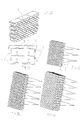
- the assembly is coherent because the blocks 1, 2, 3, 4 are assembled in alignment by one of their faces.
- the figure 1 illustrates this cooperation.
- the cohesion between blocks can be suppressed by applying a force at break zones located at the boundary between two adjacent blocks.
- the rupture zones 14 are formed here of notches formed on the one hand on a first face 5 of the construction element and on the other hand on a second face 6 located opposite the first face 5.
- the rupture zones 14 are advantageously grooves parallel and oriented along a wide dimension of the construction element perpendicular to the alignment orientation of the blocks 1, 2, 3, 4 hereinafter called depth.
- the rupture zones 14 have a notch profile higher than wide.
- their height is 13 millimeters and the width of 10 millimeters for blocks 1, 2, 3, 4 of 87 millimeters high.
- a construction element comprises 4 blocks 1, 2, 3, 4 aligned but this embodiment is not limiting and we could associate more or less blocks 1, 2, 3, 4 to form an element.
- each block 1, 2, 3, 4 comprises a groove 11 forming an inwardly recessed relief of the block 1, 2, 3, 4.
- the height the groove is less than 15% of that of the block.
- a groove of semi circular profile diameter 22 millimeters may be suitable, a height of 11 millimeters.
- the grooves 11 are advantageously identical for each of the blocks.
- the blocks 1, 2, 3, 4 are preferably identical or similar configuration.
- each block 1, 2, 3, 4 comprises a tongue 10 projecting outwards.
- Each groove 11 is opposite a tongue 10 ci although it is easily understood that the combination of a tongue of a block with a groove of another block allows their cooperation in superposition .
- a dimension and shape is provided for the tongue 10 adapted to cooperate with a groove 11 to form a male / female system.
- the tongue 10 may comprise a semi-circular profile of a diameter slightly smaller than that of the groove 11, for example a diameter of 18 millimeters corresponding to a tongue height of 9 millimeters.
- the tongues 10 are advantageously formed in a parallel manner and similar for each block 1, 2, 3, 4.
- each block 1, 2, 3, 4 In the interior volume of each block 1, 2, 3, 4 is formed a hole 15 allowing the passage of a tie rod or any other inclined means reported and allowing additional fixing of the block.
- the hole 15 of each block 1, 2, 3, 4 is aligned with the tongue 10 and the groove 11 of this block 1, 2, 3, 4.
- the assemblies are advantageously located in the middle of the depth of a block 1, 2, 3, 4, that is to say along a perpendicular dimension of the block. In this way, fewer protruding elements are present, in general, it is advantageous that the hole has a diameter less than 40% of the height of the block.
- the hole 15 is thus positioned so that the thickness of material situated around it is substantially constant for a given block 1, 2, 3, 4. Consequently, while a prejudice would be that the hole 15 weakens the block 1, 2, 3, 4, the applicant has found that the formation of the hole associated with the assembly means of the invention does not hinder the mechanical strength.
- the blocks 1, 2, 3, 4 each have a rectangular section in a plane according to the depth of the block.
- the block is not too long to ensure a better distribution of the material around the hole 15.
- a depth-to-height ratio of each block 1, 2, 3, 4 between 1 and 2 is satisfactory .
- the section can be square.
- the figure 4 shows more precisely the cooperation between two juxtaposed elements.
- two elements each consisting of 4 blocks 1, 2, 3, 4 are being approximated.
- each hole 15 of the blocks cooperates with a tie rod 12.
- the assembly makes it possible to adjust the alignment automatically between the blocks, the tie rods serving as a guide along the width of the blocks 1, 2, 3, 4.
- Tie rods of common design may be used, in particular steel rods of appropriate length for the length of the structure to be constructed.
- each tie 12 can be cut to the width of the structure and the connection can be finalized by any means for example it can be hung on concrete poles or on existing structures.
- Figures 5 to 7 illustrate different cooperation possibilities in superposition of blocks 1, 2, 3, 4 issued for the exemplary building element initially comprising 4 aligned blocks.
- a construction element has been fragmented so as to dissociate a block 1 and a block 4.
- the blocks 1 and 4 have been pivoted along a vertical axis so as to expose the face 9 obtained after dissociation to the outside.
- the blocks 2, 3 remaining of the initial building element are placed on the structure and the blocks 1, 4 after pivot are reported.
- Each block cooperates with a superimposed block by a system of groove 11 and tongue 10.
- this operation has been renewed for another building element.
- the entire structure, here a wall can be made in a similar manner and has as a whole an exploded stone appearance visible from the outside.
- a building element has been split into two parts each having two blocks 1, 2 and 3, 4.
- the two pairs of blocks are superimposed so that the block 1 is located above the block 3 and the block 2 located above of the block 4. Thanks to this configuration, one alternates lines with the appearance of exploded stone and smooth lines according to the height of the work.
- the same method is reproduced to superimpose blocks 3, 4 and blocks 1, 2 again.
- FIG 7 another modulation is obtained from a building element comprising 4 blocks 1, 2, 3, 4.
- a building element comprising 4 blocks 1, 2, 3, 4 was fragmented so as to extract the block 1 and the block 4.
- the pair of blocks 2, 3 was positioned on the wall and the blocks 1 and 4 were simply reported, after pivot of so as to expose their face 9 after dissociation outside.
- a new construction element was fragmented so as to extract the blocks 1, 4.
- the pair of blocks 2, 3 was superimposed with the blocks 1, 4 of the previous building element.
- the block 1 was superimposed on the block 2 and the block 4 superimposed on the block 1.
- a first step note the ease of manipulation and work on the element of the invention.
- the installer can work efficiently without resorting to complex machines.
- the use of a single mallet 19 is sufficient to achieve fragmentation.
- the installer exerts a force in the form of localized shock at a rupture zone which causes the separation of the blocks to the right of this rupture zone. This separation occurs while producing an exploded stone appearance on the dissociated face.
- dissociation by shocks and in particular the mallet would not be possible because it would lead to split the block in directions other than the preferred direction desired . It would then be necessary to resort to sawing machines which would strongly harm on one hand the speed and the simplicity of execution and on the other hand to the aspect of the face of the dissociated blocks which would not be any more of the type exploded stone .
- the figure 11a and the figure 11b reveal that it is possible to dissociate one or other of the blocks by simply selecting the rupture zone on which the force is exerted by means of the mallet 19.
- FIG 12 the cooperation efficiency produced by the elements of the invention has been illustrated.
- complete elements each consisting of 4 blocks 1, 2, 3, 4 are superimposed. Nevertheless, as a variant, a smaller number of blocks could be superimposed, in particular to limit the thickness of the wall construction carried out.
- Each block here cooperates with a tie 12, the assembly thus having a plurality of tie rods 12 parallel juxtaposed and superimposed.
- the diameter of the tie rods is adjusted to that of the holes so that the forces possibly applied vertically or laterally to the inner surface of the holes can be taken up by the tie rods.
- the fact that the blocks are holed does not penalize their mechanical strength.
- the global adjustment of the combination of blocks and their overall mechanical strength is significantly increased by their connection by the tie rods.
- the blocks or the superimposed elements may be separated by a geotextile-type sheet providing an interface layer between the superimposed blocks.
- a geotextile-type sheet providing an interface layer between the superimposed blocks.
- the assembly constituted by blocks derived from elements according to the invention, has a portion of cover 16 advantageously constituted by a plurality of roof pieces juxtaposed here in a horizontal direction at the upper end of the sequence in superposition of the blocks according to the invention.
- cover 16 advantageously constituted by a plurality of roof pieces juxtaposed here in a horizontal direction at the upper end of the sequence in superposition of the blocks according to the invention.
- the placement of the pieces of canopy 16 appears elsewhere in view of figure 14 at which a lower face 17 of the part 16 is visible and has a plurality of grooves 18 adapted to come in correspondence with the tabs of the blocks on which the cover is placed.
- a binder of the type small mortar can seal the canopy if necessary.
- FIGs 15 to 17 illustrate the variation capabilities offered by the invention. So, in figure 15 a wall assembly has been formed by superimposing a plurality of blocks 1, 2, 3, 4 from building elements. The blocks are simply fragmented on site after receiving the entire building elements.
- the wall thickness here corresponds to the depth of a single block.
- wall thickness is the depth of two blocks.
- construction elements with four fragmentable blocks were dislocated on site at the central failure zone so as to cut the construction elements into two equal parts. Note that all facade effects are achievable by simply choosing the orientation of the blocks relative to the desired facade.
- the figure 17 has a thickness corresponding to the depth of four blocks. In this situation, the previously described building elements are superimposed without fragmentation steps.
- the Figures 15 to 17 do not present the tie rods 12 which can be added nevertheless in order to increase the mechanical strength of the wall assembly.
- the figure 18 presents another variant embodiment of the invention in which the assembly composed by means of the construction elements also comprises additional elements 20. More precisely illustrated for side view in figure 19 the additional elements 20 are arranged similarly to the previously described construction element.
- the additional elements 20 are advantageously composed of a plurality of additional blocks joined via rupture zones similar to that presented for the construction element of the invention.
- an additional element 20 can be fragmented to obtain a plurality of additional blocks and form desired and varied thicknesses or surface conditions.
- the additional elements 20 comprise a male / female assembly system adapted to correspond with those of the blocks 1, 2, 3, 4.
- the additional elements have tabs at one of their upper face. and grooves on their underside.
- the additional elements advantageously comprise for each additional block a through hole oriented and located as the hole 15 blocks 1, 2, 3, 4.
- the through hole of the additional elements may be similar in size and section to that envisaged for the blocks 1, 2, 3, 4 and in particular the dimensional ratio previously described may be retained.
- the additional elements have a height different from the height of the building elements so as to provide variation in the stacking of the elements and additional elements 20. This possibility is illustrated in Figures 18 to 20 with additional elements 20 of greater height here, for example, twice as high as the blocks 1, 2, 3, 4
Landscapes
- Engineering & Computer Science (AREA)
- Architecture (AREA)
- Physics & Mathematics (AREA)
- Electromagnetism (AREA)
- Civil Engineering (AREA)
- Structural Engineering (AREA)
- Finishing Walls (AREA)
- Toys (AREA)
Applications Claiming Priority (1)
| Application Number | Priority Date | Filing Date | Title |
|---|---|---|---|
| FR1156407A FR2977904B1 (fr) | 2011-07-13 | 2011-07-13 | Bloc de construction |
Publications (1)
| Publication Number | Publication Date |
|---|---|
| EP2546427A1 true EP2546427A1 (de) | 2013-01-16 |
Family
ID=46384262
Family Applications (1)
| Application Number | Title | Priority Date | Filing Date |
|---|---|---|---|
| EP12174961A Withdrawn EP2546427A1 (de) | 2011-07-13 | 2012-07-04 | Blockbaustein |
Country Status (2)
| Country | Link |
|---|---|
| EP (1) | EP2546427A1 (de) |
| FR (1) | FR2977904B1 (de) |
Cited By (1)
| Publication number | Priority date | Publication date | Assignee | Title |
|---|---|---|---|---|
| FR3017142A1 (fr) * | 2014-02-04 | 2015-08-07 | Dominique Rossi | Element de construction comportant au moins deux blocs |
Citations (7)
| Publication number | Priority date | Publication date | Assignee | Title |
|---|---|---|---|---|
| DE8009618U1 (de) * | 1980-04-08 | 1980-08-07 | Greisel-Baustoff-Gmbh, 8359 Ortenburg | Gasbetonelement mit aussparungen |
| EP0261101A2 (de) * | 1986-09-15 | 1988-03-23 | Rudolf Schmaranz | Bauelement sowie Verfahren zu dessen Herstellung |
| WO1996022427A1 (fr) | 1995-01-18 | 1996-07-25 | Jacqueline Scagni | Elements de construction pour monter a sec des murs de soutenement a inclinaison variable |
| DE19517784A1 (de) * | 1995-05-15 | 1996-11-21 | Kann Baustoffwerke Gmbh | Bausatz und Verfahren zum Errichten von Trockenmauern mit wenigstens einseitig gebrochener Sichtfläche |
| US20030200716A1 (en) * | 2002-04-29 | 2003-10-30 | Manthei Benjamin R. | System for interconnecting wall blocks |
| WO2005108698A1 (en) | 2004-04-29 | 2005-11-17 | Keystone Retaining Wall Systems, Inc. | Wall block system |
| DE212006000032U1 (de) * | 2005-07-21 | 2007-12-27 | Gmundner Fertigteile Ges.M.B.H. & Co. Kg | Kanalsystem |
-
2011
- 2011-07-13 FR FR1156407A patent/FR2977904B1/fr active Active
-
2012
- 2012-07-04 EP EP12174961A patent/EP2546427A1/de not_active Withdrawn
Patent Citations (7)
| Publication number | Priority date | Publication date | Assignee | Title |
|---|---|---|---|---|
| DE8009618U1 (de) * | 1980-04-08 | 1980-08-07 | Greisel-Baustoff-Gmbh, 8359 Ortenburg | Gasbetonelement mit aussparungen |
| EP0261101A2 (de) * | 1986-09-15 | 1988-03-23 | Rudolf Schmaranz | Bauelement sowie Verfahren zu dessen Herstellung |
| WO1996022427A1 (fr) | 1995-01-18 | 1996-07-25 | Jacqueline Scagni | Elements de construction pour monter a sec des murs de soutenement a inclinaison variable |
| DE19517784A1 (de) * | 1995-05-15 | 1996-11-21 | Kann Baustoffwerke Gmbh | Bausatz und Verfahren zum Errichten von Trockenmauern mit wenigstens einseitig gebrochener Sichtfläche |
| US20030200716A1 (en) * | 2002-04-29 | 2003-10-30 | Manthei Benjamin R. | System for interconnecting wall blocks |
| WO2005108698A1 (en) | 2004-04-29 | 2005-11-17 | Keystone Retaining Wall Systems, Inc. | Wall block system |
| DE212006000032U1 (de) * | 2005-07-21 | 2007-12-27 | Gmundner Fertigteile Ges.M.B.H. & Co. Kg | Kanalsystem |
Cited By (2)
| Publication number | Priority date | Publication date | Assignee | Title |
|---|---|---|---|---|
| FR3017142A1 (fr) * | 2014-02-04 | 2015-08-07 | Dominique Rossi | Element de construction comportant au moins deux blocs |
| WO2015117827A1 (fr) * | 2014-02-04 | 2015-08-13 | Dominique Rossi | Element de construction comportant au moins deux blocs |
Also Published As
| Publication number | Publication date |
|---|---|
| FR2977904A1 (fr) | 2013-01-18 |
| FR2977904B1 (fr) | 2015-01-02 |
Similar Documents
| Publication | Publication Date | Title |
|---|---|---|
| EP3494315B1 (de) | Klammer zum zusammenhalten zweier flächiger teile | |
| CA2714270C (fr) | Ancre de manutention d'elements de construction aux branches divergentes maintenues | |
| EP0097659B1 (de) | Dreidimensionale monolithische aus gestrecktem metall bestehende struktur, insbesondere als bewehrung einer bauplatte | |
| EP3022362B1 (de) | Baublock und wand aus mindestens zwei solchen überlagerten blöcken | |
| FR2951755A1 (fr) | Entrevous de plancher en matiere plastique expansee | |
| EP2546427A1 (de) | Blockbaustein | |
| EP3102751B1 (de) | Konstruktionselement mit mindestens zwei blöcken | |
| CH699202A1 (fr) | Bloc de construction de murs. | |
| EP1039038B1 (de) | Ausschalungshilfsvorrichtung | |
| FR2809143A1 (fr) | Dispositif d'assemblage de panneaux de bois | |
| FR2696201A1 (fr) | Elément de construction préfabriqué pour la réalisation de murs. | |
| WO2019166384A1 (fr) | Elément de construction | |
| FR2944036A1 (fr) | Bloc modulaire, ensemble de blocs et procede d'assemblage desdits blocs pour la realisation de paroi ou mur de construction en bois | |
| FR2518611A1 (fr) | Panneau prefabrique pour constructions immobilieres | |
| FR2550811A1 (fr) | Jeu d'elements de construction pour mur de soutenement | |
| FR3047757A1 (fr) | Rupteur thermique, entrevous isolant associe et plancher isolant obtenu | |
| EP4105498A1 (de) | Kit und verfahren zur montage eines elements eines möbelstücks und element eines möbelstücks | |
| BE1012297A6 (fr) | Prelinteau en beton arme. | |
| EP4207506A1 (de) | Bausatz für einen elektrischen verbinder und elektrischer verbinder | |
| FR3010104A1 (fr) | Ensemble d'au moins deux blocs de construction avec des moyens d'aide a la desolidarisation et paroi murale formee de tels ensembles et/ou de blocs sectionnes de tels ensembles | |
| FR2983504A1 (fr) | Entrevous de coffrage et/ou isolant integrant un element formant correcteur de pont thermique. | |
| WO2018042083A1 (fr) | Ancre dynamique renforcee de levage, de relevage, de retournement d'un element de construction | |
| EP3164553A1 (de) | Abstandshalter zum brechen von wärmebrücken mit verstärkungsdomen, verwendung davon und zugehörige konstruktionsvorrichtung | |
| WO2004016862A1 (fr) | Element de construction pour la realisation d'un mur de soutenement | |
| WO2002035015A1 (fr) | Element de construction et mur de soutenement l'integrant |
Legal Events
| Date | Code | Title | Description |
|---|---|---|---|
| PUAI | Public reference made under article 153(3) epc to a published international application that has entered the european phase |
Free format text: ORIGINAL CODE: 0009012 |
|
| AK | Designated contracting states |
Kind code of ref document: A1 Designated state(s): AL AT BE BG CH CY CZ DE DK EE ES FI FR GB GR HR HU IE IS IT LI LT LU LV MC MK MT NL NO PL PT RO RS SE SI SK SM TR |
|
| AX | Request for extension of the european patent |
Extension state: BA ME |
|
| 17P | Request for examination filed |
Effective date: 20130709 |
|
| RBV | Designated contracting states (corrected) |
Designated state(s): AL AT BE BG CH CY CZ DE DK EE ES FI FR GB GR HR HU IE IS IT LI LT LU LV MC MK MT NL NO PL PT RO RS SE SI SK SM TR |
|
| 17Q | First examination report despatched |
Effective date: 20160414 |
|
| STAA | Information on the status of an ep patent application or granted ep patent |
Free format text: STATUS: THE APPLICATION IS DEEMED TO BE WITHDRAWN |
|
| 18D | Application deemed to be withdrawn |
Effective date: 20160825 |