EP2546437A2 - Containersicherheitsvorrichtung - Google Patents
Containersicherheitsvorrichtung Download PDFInfo
- Publication number
- EP2546437A2 EP2546437A2 EP11753564A EP11753564A EP2546437A2 EP 2546437 A2 EP2546437 A2 EP 2546437A2 EP 11753564 A EP11753564 A EP 11753564A EP 11753564 A EP11753564 A EP 11753564A EP 2546437 A2 EP2546437 A2 EP 2546437A2
- Authority
- EP
- European Patent Office
- Prior art keywords
- container
- opening
- module
- power
- closing
- Prior art date
- Legal status (The legal status is an assumption and is not a legal conclusion. Google has not performed a legal analysis and makes no representation as to the accuracy of the status listed.)
- Withdrawn
Links
Images


Classifications
-
- E—FIXED CONSTRUCTIONS
- E05—LOCKS; KEYS; WINDOW OR DOOR FITTINGS; SAFES
- E05B—LOCKS; ACCESSORIES THEREFOR; HANDCUFFS
- E05B73/00—Devices for locking portable objects against unauthorised removal; Miscellaneous locking devices
- E05B73/0017—Anti-theft devices, e.g. tags or monitors, fixed to articles, e.g. clothes, and to be removed at the check-out of shops
- E05B73/0023—Containers, boxes, cases or the like, e.g. for compact discs or video-cassettes, specially adapted therefor
-
- E—FIXED CONSTRUCTIONS
- E05—LOCKS; KEYS; WINDOW OR DOOR FITTINGS; SAFES
- E05C—BOLTS OR FASTENING DEVICES FOR WINGS, SPECIALLY FOR DOORS OR WINDOWS
- E05C19/00—Other devices specially designed for securing wings, e.g. with suction cups
- E05C19/18—Portable devices specially adapted for securing wings
- E05C19/186—Portable devices specially adapted for securing wings with a pair of hooks, which are movable towards each other for grasping of an element on the wing, respectively on the frame, or for grasping of an element on each of the wings forming a double door
-
- B—PERFORMING OPERATIONS; TRANSPORTING
- B65—CONVEYING; PACKING; STORING; HANDLING THIN OR FILAMENTARY MATERIAL
- B65D—CONTAINERS FOR STORAGE OR TRANSPORT OF ARTICLES OR MATERIALS, e.g. BAGS, BARRELS, BOTTLES, BOXES, CANS, CARTONS, CRATES, DRUMS, JARS, TANKS, HOPPERS, FORWARDING CONTAINERS; ACCESSORIES, CLOSURES, OR FITTINGS THEREFOR; PACKAGING ELEMENTS; PACKAGES
- B65D90/00—Component parts, details or accessories for large containers
-
- E—FIXED CONSTRUCTIONS
- E05—LOCKS; KEYS; WINDOW OR DOOR FITTINGS; SAFES
- E05B—LOCKS; ACCESSORIES THEREFOR; HANDCUFFS
- E05B39/00—Locks giving indication of authorised or unauthorised unlocking
-
- E—FIXED CONSTRUCTIONS
- E05—LOCKS; KEYS; WINDOW OR DOOR FITTINGS; SAFES
- E05B—LOCKS; ACCESSORIES THEREFOR; HANDCUFFS
- E05B39/00—Locks giving indication of authorised or unauthorised unlocking
- E05B39/005—Locks with means for tracking the location of locked items, e.g. freight containers
-
- E—FIXED CONSTRUCTIONS
- E05—LOCKS; KEYS; WINDOW OR DOOR FITTINGS; SAFES
- E05B—LOCKS; ACCESSORIES THEREFOR; HANDCUFFS
- E05B47/00—Operating or controlling locks or other fastening devices by electric or magnetic means
- E05B47/0001—Operating or controlling locks or other fastening devices by electric or magnetic means with electric actuators; Constructional features thereof
-
- E—FIXED CONSTRUCTIONS
- E05—LOCKS; KEYS; WINDOW OR DOOR FITTINGS; SAFES
- E05B—LOCKS; ACCESSORIES THEREFOR; HANDCUFFS
- E05B17/00—Accessories in connection with locks
- E05B17/22—Means for operating or controlling lock or fastening device accessories, i.e. other than the fastening members, e.g. switches, indicators
- E05B17/226—Displays on locks, e.g. LED or LCD screens
-
- E—FIXED CONSTRUCTIONS
- E05—LOCKS; KEYS; WINDOW OR DOOR FITTINGS; SAFES
- E05B—LOCKS; ACCESSORIES THEREFOR; HANDCUFFS
- E05B47/00—Operating or controlling locks or other fastening devices by electric or magnetic means
- E05B2047/0097—Operating or controlling locks or other fastening devices by electric or magnetic means including means for monitoring voltage, e.g. for indicating low battery state
-
- E—FIXED CONSTRUCTIONS
- E05—LOCKS; KEYS; WINDOW OR DOOR FITTINGS; SAFES
- E05B—LOCKS; ACCESSORIES THEREFOR; HANDCUFFS
- E05B45/00—Alarm locks
- E05B45/005—Chain-locks, cable-locks or padlocks with alarms
-
- E—FIXED CONSTRUCTIONS
- E05—LOCKS; KEYS; WINDOW OR DOOR FITTINGS; SAFES
- E05B—LOCKS; ACCESSORIES THEREFOR; HANDCUFFS
- E05B83/00—Vehicle locks specially adapted for particular types of wing or vehicle
- E05B83/02—Locks for railway freight-cars, freight containers or the like; Locks for the cargo compartments of commercial lorries, trucks or vans
- E05B83/08—Locks for railway freight-cars, freight containers or the like; Locks for the cargo compartments of commercial lorries, trucks or vans with elongated bars for actuating the fastening means
- E05B83/10—Rotary bars
-
- Y—GENERAL TAGGING OF NEW TECHNOLOGICAL DEVELOPMENTS; GENERAL TAGGING OF CROSS-SECTIONAL TECHNOLOGIES SPANNING OVER SEVERAL SECTIONS OF THE IPC; TECHNICAL SUBJECTS COVERED BY FORMER USPC CROSS-REFERENCE ART COLLECTIONS [XRACs] AND DIGESTS
- Y10—TECHNICAL SUBJECTS COVERED BY FORMER USPC
- Y10T—TECHNICAL SUBJECTS COVERED BY FORMER US CLASSIFICATION
- Y10T70/00—Locks
- Y10T70/50—Special application
- Y10T70/5004—For antitheft signaling device on protected article
Definitions
- the present invention relates to a container security apparatus, and more particularly, to a container security apparatus for safely transporting a container.
- containers are widely used as means for shipping goods. Particularly, when transporting goods by land from a harbor to an airport, goods are loaded in containers and transported using vehicles.
- Such containers are left as they are in a harbor that is a starting point for a long period or are transported for a long time to a destination in a state of transporting via vehicles. In this case, there occur many robbery cases of goods loaded in containers.
- General containers include door latch mechanism to lock a door thereof.
- a seal itself may be unsealed using a general cutting device or it is easy to take the seal to pieces by using a duplication thereof.
- An aspect of the present invention provides a container security apparatus attached to both opening/closing bars of a container to be detachable to sense whether the container is opened or not and transmitting the sensed opening/closing information to a remote location to check in real time whether the container is sealed or not, thereby safely transporting the container.
- An aspect of the present invention also provides a container security apparatus capable of checking a present location of a container and checking a case when a container deviates from the designated path in real time.
- a container security apparatus including: a main cover unit with a display part displaying a present state; a main frame coupled with the main cover unit internally, including a first insertion part surrounding one of both opening/closing bars of a container, formed on one side thereof; a first body unit coupled with the main frame internally, including a power-supply part with a built-in battery for supplying power stably mounted thereon; and a sensing part including a guide groove formed penetrating thereinside, a plurality of coupling holes connected to the guide groove, into which a coupling element is inserted, and a sealing sensor whose one end is connected to the coupling element, sensing whether the container is opened or not; a second body unit coupled with the first body unit internally, including an antenna part with a built-in antenna stably mounted thereon; and a board part with a board stably mounted thereon, the board including a sealing module electrically connected to another end of the sealing sensor and transmitting the opening
- the lock frame may include a wire line formed thereinside, where the wire is inserted in and fastened thereto.
- the lock frame may include a wire groove formed thereinside, where the wire passes through and is fastened thereto.
- the lock frame may be formed of stainless steel.
- the flat plates may include: a first flat plate connected between one end of the second insertion part and the detachable plate in a single body; and a second flat plate connected to another end of the second insertion part in a single body, wherein the wire is continuously formed from the detachable plate to the second flat plate.
- conductive elements respectively, electrically connected to the coupling element.
- the communication module may be formed of one of code division multiple access (CDMA), wideband code division multiple access (WCDMA), wireless broadband Internet (WiBro), wireless fidelity (WiFi), and global system/standard for mobile communication (GSM) module.
- CDMA code division multiple access
- WCDMA wideband code division multiple access
- WiBro wireless broadband Internet
- WiFi wireless fidelity
- GSM global system/standard for mobile communication
- the board may further include a database (DB) module for storing container information such as a transfer path, a number, and a license plate number of the container.
- DB database
- the board may further include a warning module generating and transmitting an alarm signal when the container is deviated from a transfer path thereof or sealing of the container is illegally released.
- the apparatus may further include, when the alarm signal is generated, function of resetting data stored when illegally opening the container, arbitrarily operating the container, or turning off the power of the container.
- the warning module may generate and transmit the alarm signal when a present charge capacity of the built-in battery is 25% or less of a maximum charge capacity thereof.
- the insertion part may include: a sub frame connected to one end of the main frame in a single body and surrounding the opening/closing bar; a compression controller including a shaft whose both ends are fastened to the sub frame externally, a compression cam rotation on an axis of the shaft, and an opening/closing handle connected to the compression cam in a single body; a tightening element installed inside the sub frame and transferred toward the opening/closing bar by a pressure applied by the compression cam; a spring section installed on both sides of the shaft and connected from the outside of the sub frame to a top of the tightening element; and a buffering element installed inside between the tightening element and the sub frame and relieving an impact with the opening/closing bar and improving a grip force.
- the spring section may include: a plurality of vertical supporters whose one end is vertically connected to the tightening element; a plurality of springs provided surrounding the outside of the vertical supporters; and a spring stopper provided on other ends of the vertical supporters and connecting the plurality of vertical supporters.
- a buffering element relieving an impact with the opening/closing bar and improving a grip force.
- the buffering element may be formed of a material capable of improving the grip force by strengthening a frictional force such as rubber.
- the power-supply part may include a power-supply switch formed on one side thereof, the power-supply switch turned on when the lock frame is coupled with the sensing part and turned off when the lock frame is detached from the sensing part.
- the power-supply part may turn on the power when the lock frame is coupled with the sensing part and the opening/closing handle is pressurized and may turn off the power when the lock frame is detached from the sensing part and the opening/closing handle is relieved.
- the power-supply part may include a battery port for electrically charging the built-in battery.
- the coupling element may be formed of one of a pin, a bolt, and a switch.
- the display part may display a state whether the power is turned on or off, a state of a residual amount of the battery, a communication state, and a sealed state.
- the main cover unit may include a sub cover part covering the coupling element and preventing malfunction of the coupling element.
- the container security apparatus provides an effect of safely transporting the container by easily attaching/detaching the apparatus to/from both opening/closing bars of a container, sensing whether the container is opened or not, transmitting opening/closing information to a remote location, and checking whether the container is sealed or not in real-time.
- the apparatus provides an effect of checking in real-time a location of the container and whether the container is deviated from a transfer path thereof.
- the apparatus provides an effect of being applied to not only container vehicles but also various vehicles transferred maintaining security thereof such as refrigerator vehicles.
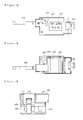
- FIG. 1 is a front view illustrating a container security apparatus according to an embodiment of the present invention
- FIG. 2 is a rear view illustrating the container security apparatus of FIG. 1
- FIG. 3 is a left-side view illustrating the container security apparatus of FIG. 1
- FIG. 4 is a right-side view illustrating the container security apparatus of FIG. 1
- FIG. 5 is a top view illustrating the container security apparatus of FIG. 1
- FIG. 6 is a bottom view illustrating the container security apparatus of FIG. 1
- FIG. 7 is a schematic perspective view illustrating the container security apparatus of FIG. 1 ;
- the container security apparatus includes, as shown in FIGs. 1 to 7 , a main cover unit 100, a main frame 200, a first body unit 300, a second body unit 400, and a lock frame 600.
- FIG. 8 is a configuration view illustrating the main cover unit 100 of the container security apparatus according to an embodiment of the present invention.
- the main cover unit 100 is coupled with the main frame 200 externally, covers the main frame 200 and a first insertion part 500 that will be described later, and includes a display part 110 and a sub cover part 120.
- the display part 110 displays a present state of the container security apparatus.
- the sub cover part 120 covers a coupling element 323 passing through and coupled with the main cover unit 100, which will be described later, and prevents the malfunction of the coupling element 323.
- FIG. 9 is a configuration view illustrating the main frame 200 of the container security apparatus according to an embodiment of the present invention.
- the main frame 200 is coupled with the main cover unit 100 internally and equipped with the first insertion part 500 covering and fastened to one of both opening/closing bars of a container on one side thereof.
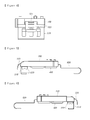
- FIG. 18 is a view illustrating the opening/closing bar 700 fastened to the first insertion part 500 according to an embodiment of the present invention
- FIG. 19 is a view illustrating an operation of fastening the opening/closing bar 700 to the first insertion part 500 according to the present invention.
- the first insertion part 500 includes a sub frame 510, a compression controller 520, a tightening element 530, a spring section 540, and a buffering element 550.
- the sub frame 510 is connected to one side of the main frame 200 in a single body and may surround and support the opening/closing bar 700 externally.
- the compression controller 520 may perform one of fastening the opening/closing bar 700 to the first insertion part 500 and separating the opening/closing bar 700 from the first insertion part 500, as shown in FIGs. 4 and 18 , may include a shaft 521, a compression cam 522, and an opening/closing handle 523.
- the tightening element 530 is installed inside the sub frame 510 and transfers toward the opening/closing bar 700 due to a pressure of the compression cam 520, and may be closely attached to the opening/closing bar 700.
- the spring section 540 is installed on both sides of the shaft 521, may be connected from the outside of the sub frame 510 to a top of the tightening element 530, and may restore the tightening element 530 to an original location thereof when the opening/closing handle 523 is rotationally transferred from a bottom to a top to release the pressure of the compression cam 522 toward the tightening element 530.
- the buffering element 550 is provided inside between the tightening element 530 and the sub frame 510 to buffer an impact between the tightening element 530 and the opening/closing bar 700 and may improve grip thereof.
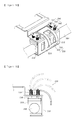
- FIG. 10 is a configuration view illustrating the first body unit 300 of the container security apparatus according to an embodiment of the present invention
- FIG. 21 is a view illustrating an operation of turning on or off a power-supply switch 312 according to an embodiment of the present invention.
- the first body unit 300 is coupled with the main frame 200 internally and includes, as shown in FIG. 10 , a power-supply part 310 and a sensing part 320.
- the power-supply part 310 includes a built-in battery 311 stably mounted thereon to apply power and the power-supply switch 312 turned on when the lock frame 600 is coupled with the sensing part 320 and turned off when the lock frame 600 is detached from the sensing part 320 and simultaneously, the compression of the opening/closing handle 523 is released to separate the opening/closing bar 700 from the first insertion part 500.
- FIG. 14 is a cross-sectional view illustrating the lock frame 600 coupled with the sensing part 320 according to an embodiment of the present invention.
- the sensing part 320 includes, as shown in FIG. 14 , a guide groove 321, a plurality of coupling holes 322, and a sealing sensor 324.
- FIG. 11 is a configuration view illustrating the second body unit 400 of the container security apparatus according to an embodiment of the present invention.
- the second body unit 400 is coupled with the first body unit 300 internally and includes, as shown in FIG. 11 , an antenna part 410 and a board part 420.
- the antenna part 410 includes a built-in antenna stably mounted thereon.
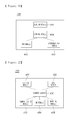
- FIGS. 16 and 17 are block views illustrating a board 430 according to an embodiment of the present invention.
- the board part 420 includes the board 430 stably mounted thereon, and the board 430 includes, as shown in FIG. 16 , a sealing module 431, a global positioning system (GPS) module 432, a communication module 433, and a control module 436.
- a sealing module 431 includes, as shown in FIG. 16 , a sealing module 431, a global positioning system (GPS) module 432, a communication module 433, and a control module 436.
- GPS global positioning system
- FIGs. 12 and 13 are configuration views illustrating the lock frame 600 of the container security apparatus according to an embodiment of the present invention.
- the lock frame 600 may be formed of stainless steel and includes, as shown in FIGS. 12 and 13 , a second insertion part 610, flat plates 620, a detachable plate 630, and a wire 640.
- FIG. 20 is a view illustrating the opening/closing bar 700 fastened to the second insertion part 610 according to an embodiment of the present invention.
- the second insertion part 610 surrounds another opening/closing bar 700 of the container and is fastened thereto as shown in FIG. 20 .
- the flat plate is, as shown in FIGs. 12 and 13 , connected to both ends of the second insertion part 610 in a single body.
- FIG. 15 is a partial top view illustrating the detachable plate 630 according to an embodiment of the present invention.
- the detachable plate 630 is, as shown in FIG. 15 , connected to one of two flat plates 620, for example, a first flat plate 621 and includes a plurality of detachable holes 631 corresponding to coupling holes 322.
- the detachable plate 630 is slidably inserted into the guide groove 321 in such a way that the detachable hole 631 corresponds to a location of the coupling hole 322 and is coupled with the sensing part 320 by the coupling element 323.
- the wire 640 includes, as shown in FIGs. 12 and 13 , one end connected an input detachable hole 631a and another end connected to an output detachable hole 631b and is provided from the detachable plate 630 to the second flat plate 622.
- FIG. 1 is a front view illustrating a container security apparatus according to an embodiment of the present invention
- FIG. 2 is a rear view illustrating the container security apparatus of FIG. 1
- FIG. 3 is a left-side view illustrating the container security apparatus of FIG. 1
- FIG. 4 is a right-side view illustrating the container security apparatus of FIG. 1
- FIG. 5 is a top view illustrating the container security apparatus of FIG. 1
- FIG. 6 is a bottom view illustrating the container security apparatus of FIG. 1
- FIG. 7 is a schematic perspective view illustrating the container security apparatus of FIG. 1 ;
- the container security apparatus includes, as shown in FIGs. 1 to 7 , a main cover unit 100, a main frame 200, a first body unit 300, a second body unit 400, and a lock frame 600.
- FIG. 8 is a configuration view illustrating the main cover unit 100 of the container security apparatus according to an embodiment of the present invention.
- the main cover unit 100 is coupled with the main frame 200 externally, covers the main frame 200 and a first insertion part 500 that will be described later, and includes a display part 110 and a sub cover part 120.
- the display part 110 displays a present state of the container security apparatus.
- the display part 110 may be formed of one of a liquid crystal display (LCD) and a light-emitting diode (LED) and may display the present status of the container security apparatus such as the status of turning the container security apparatus on/off, the status of a residual quantity of a battery, a status of communication, and a status of sealing.
- LCD liquid crystal display
- LED light-emitting diode
- the sub cover part 120 covers a coupling element 323 passing through and coupled with the main cover unit 100, which will be described later, and prevents the malfunction of the coupling element 323.
- the sub cover part 120 may open or shut the coupling element 323 by slidably transferring on the main cover unit 100 or by using a hinge.
- FIG. 9 is a configuration view illustrating the main frame 200 of the container security apparatus according to an embodiment of the present invention.
- the main frame 200 is coupled with the main cover unit 100 internally and equipped with the first insertion part 500 covering and fastened to one of both opening/closing bars of a container on one side thereof.
- FIG. 18 is a view illustrating the opening/closing bar 700 fastened to the first insertion part 500 according to an embodiment of the present invention
- FIG. 19 is a view illustrating an operation of fastening the opening/closing bar 700 to the first insertion part 500 according to the present invention.
- the first insertion part 500 includes a sub frame 510, a compression controller 520, a tightening element 530, a spring section 540, and a buffering element 550.
- the sub frame 510 is connected to one side of the main frame 200 in a single body and may surround and support the opening/closing bar 700 externally.
- the sub frame 510 may be formed in various shapes, and more particularly, a shape of " ⁇ " in the present embodiment.
- the compression controller 520 may perform one of fastening the opening/closing bar 700 to the first insertion part 500 and separating the opening/closing bar 700 from the first insertion part 500, as shown in FIGs. 4 and 18 , may include a shaft 521, a compression cam 522, and an opening/closing handle 523.
- the shaft 521 passes through a hollow portion of the compression cam 522 and both ends thereof are fastened to the outside of the sub frame 510.
- the compression cam 522 is formed in a rectangular shape whose one set of sides are longer than another set of sides and is rotationally transferred on an axis of the shaft 521.
- the opening/closing handle 523 is formed in a parabolic shape with a fluent curve portion formed thereon and is connected to the compression cam 522 in a single body, thereby transferring a rotational force to the compression cam 522.
- the opening/closing handle 523 is rotationally transferred from a top to a bottom in such a way that the compression cam 522 simultaneously rotates on an axis of the shaft 521 and the tightening element 530 is compressed.
- the tightening element 530 is installed inside the sub frame 510 and transfers toward the opening/closing bar 700 due to a pressure of the compression cam 520, and may be closely attached to the opening/closing bar 700.
- the spring section 540 is installed on both sides of the shaft 521, may be connected from the outside of the sub frame 510 to a top of the tightening element 530, and may restore the tightening element 530 to an original location thereof when the opening/closing handle 523 is rotationally transferred from a bottom to a top to release the pressure of the compression cam 522 toward the tightening element 530.
- the spring section 540 includes, as shown in FIG. 18 , a plurality of vertical supporters 541, a plurality of springs 543, and a spring stopper 542.
- the vertical supporter 541 includes one end connected vertically to the tightening element 530 and another end projected outside the sub frame 510, thereby supporting the tightening element 530.
- the spring 543 is provided surrounding the outside of the vertical supporter 541 and may generate a restoring force to the tightening element 530 depending on contraction and relaxation thereof.
- the spring stopper 542 may be provided to the other ends of the vertical supporters 541 to connect the plurality of vertical supporters 541 to one another and may generate an elasticity force to the spring 543 by contracting the spring 543 when the compression cam 522 compresses the tightening element 530.
- the buffering element 550 is provided inside between the tightening element 530 and the sub frame 510 to buffer an impact between the tightening element 530 and the opening/closing bar 700 and may improve grip thereof.
- the opening/closing bar 700 is closely attached and fastened to the buffering element 550 transferred by the compression controller 520, whose impact is relieved by the buffering element 550 provided inside between the tightening element 530 and the sub frame 510, thereby being fastened while improving grip thereof.
- the buffering element 550 may be formed of a material capable of improving a grip force by strengthening a frictional force such as rubber.
- FIG. 10 is a configuration view illustrating the first body unit 300 of the container security apparatus according to an embodiment of the present invention
- FIG. 21 is a view illustrating an operation of turning on or off a power-supply switch 312 according to an embodiment of the present invention.
- the first body unit 300 is coupled with the main frame 200 internally and includes, as shown in FIG. 10 , a power-supply part 310 and a sensing part 320.
- the power-supply part 310 includes a built-in battery 311 stably mounted thereon to apply power and the power-supply switch 312 turned on when the lock frame 600 is coupled with the sensing part 320 and turned off when the lock frame 600 is detached from the sensing part 320.
- the power-supply switch 312 may be pressed by a pressure applied by the detachable plate 630 and turn power on when the detachable plate 630 of the lock frame 600, which will be described later, is coupled with the sensing part 320 and may return to an original location thereon and turn the power off due to a removal of the pressure applied by the detachable plate 630 when the detachable plate 630 is detached from the sensing part 320.
- the power-supply part 310 may include a battery port, not shown, to electrically charge the built-in battery 311, which may be formed of 8-celled nickel-hydro battery.
- the power-supply part 310 may be formed to turn the power on when the lock frame 600 is coupled with the sensing part 320 and simultaneously, the opening/closing handle 523 of the compression controller 520 is compressed and fastens the opening/closing bar 700 to the first insertion part 500 and to turn the power off when the lock frame 600 is detached from the sensing part 320
- FIG. 14 is a cross-sectional view illustrating the lock frame 600 coupled with the sensing part 320 according to an embodiment of the present invention.
- the sensing part 320 includes, as shown in FIG. 14 , a guide groove 321, a plurality of coupling holes 322, and a sealing sensor 324.
- the guide groove 321 may be formed to pass through inside the sensing part 320, into which the lock frame may be slidably inserted.
- the coupling hole 322 is connected to the guide groove 321, the coupling hole in which the coupling element 323 may be inserted.
- the coupling element 323 may be formed of one of a pin, a bolt, and a switch.
- the sealing sensor 324 includes one end connected to the coupling element 323 and other end electrically connected to a sealing module 431 of the board 430, which will be described later, when the coupling element 323 is inserted into the coupling hole 322, thereby sensing whether the container is open or closed.
- FIG. 11 is a configuration view illustrating the second body unit 400 of the container security apparatus according to an embodiment of the present invention.
- the second body unit 400 is coupled with the first body unit 300 internally and includes, as shown in FIG. 11 , an antenna part 410 and a board part 420.
- the antenna part 410 includes a built-in antenna stably mounted thereon.
- FIGs. 16 and 17 are block views illustrating a board 430 according to an embodiment of the present invention.
- the board part 420 includes the board 430 stably mounted thereon, and the board 430 includes, as shown in FIG. 16 , a sealing module 431, a global positioning system (GPS) module 432, a communication module 433, and a control module 436.
- a sealing module 431 includes, as shown in FIG. 16 , a sealing module 431, a global positioning system (GPS) module 432, a communication module 433, and a control module 436.
- GPS global positioning system
- the sealing module 431 is electrically connected to another end of the sealing sensor 324 and transmits information on whether the container is opened or not according to a sensing signal of the sealing sensor 324 to the control module 436.
- FIG. 22 is a circuit diagram illustrating the sealing module 431 of the board 430 according to an embodiment of the present invention.
- a GPIO signal of a central processing unit may become HIGH.
- the sealing sensor 324 is not electrically connected to the NODE 2, since the contact point is shortcircuited, the GPIO signal of the CPU may become LOW.
- the sealing maintenance information may be transmitted when the GPIO signal is HIGH and it is considered as the sealed state
- the release information may be transmitted when the GPIO signal is LOW and it is considered as the release state.
- the GPS module 432 senses a real-time location of the container and transmits the location information thereof to the control module 436.
- the GPS module 432 may be connected to the control module 436 using a serial interface, may be modulated by applying location information analysis application via universal asynchronous receiver transmitter (UART), and may transmit the location information to the control module 436 periodically, for example, every one minute.
- UART universal asynchronous receiver transmitter
- the communication module 433 receives the opening/closing information and the location information from the control module 436 and transmits the same to an administration server.
- the communication module 433 may be connected to the control module 436 using a serial interface, may be modulated by applying an Internet communication application via UART such as transmission control protocol/Internet protocol (TCP/IP), and may transmit the opening/closing information and the location information to the administration server via Internet.
- UART such as transmission control protocol/Internet protocol (TCP/IP)
- TCP/IP transmission control protocol/Internet protocol
- the communication module 433 may be formed of one of code division multiple access (CDMA), wideband code division multiple access (WCDMA), wireless broadband Internet (WiBro), wireless fidelity (WiFi), and global system/standard for mobile communication (GSM) module.
- CDMA code division multiple access
- WCDMA wideband code division multiple access
- WiBro wireless broadband Internet
- WiFi wireless fidelity
- GSM global system/standard for mobile communication
- the control module 436 receives the opening/closing information and the location information, transmits the same to the communication module 433, and controls the sealing module 431, the GPS module 432, and the communication module 433.
- the board 430 may further include a database (DB) module 434 and a warning module 435, as shown in FIG. 17 .
- DB database
- the DB module 434 is controlled by the control module 436 and stores information on the container, such as a transfer path thereof, the number of the container, a license plate number of the container.
- the warning module 435 is controlled by the control module 436 and generates and transmits an alarm signal to the control module 436 when the container is deviated from a transfer path thereof stored in the DB module 434 or sealing of the container is released and the sealing module 431 transmits the release information to the control module 436.
- the alarm signal is transmitted from the control module 436 to the communication module 433 and may be transmitted to the administration server in real-time via the communication module 433.
- warning module 435 may generate and transmit an alarm signal to the control module 436 when a present charge capacity of the built-in battery is 25% or less of a maximum charge capacity thereof.
- FIGs. 12 and 13 are configuration views illustrating the lock frame 600 of the container security apparatus according to an embodiment of the present invention.
- the lock frame 600 may be formed of stainless steel and includes, as shown in FIGs. 12 and 13 , a second insertion part 610, flat plates, a detachable plate 630, and a wire 640.
- FIG. 20 is a view illustrating the opening/closing bar 700 fastened to the second insertion part 610 according to an embodiment of the present invention.
- the second insertion part 610 surrounds another opening/closing bar 700 of the container and is fastened thereto as shown in FIG. 20 .
- the second insertion part 610 may be formed in a U shape with a fluent curved portion, inside which a buffering element 611 is provided, in such a way that an impact between the second insertion part 610 and the opening/closing bar is relieved and a grip force may be improved.
- the buffering element 611 may be formed of a material capable of improving the grip force by strengthening a frictional force such as rubber.
- the flat plate is connected to both ends of the second insertion part 610 in a single body as shown in FIGs. 12 and 13 .
- the flat plate may include a first flat plate 621 connected between one end of the second insertion part 610 and the detachable plate 630 in a single body and a second flat plate 622 connected to the first flat plate 621 and another end of the second insertion part 610 in a single body.
- FIG. 15 is a partial top view illustrating the detachable plate 630 according to an embodiment of the present invention.
- the detachable plate 630 is, as shown in FIG. 15 , connected to one of two flat plates 620, for example, the first flat plate 621 and includes a plurality of detachable holes 631 corresponding to coupling holes 322.
- the detachable plate 630 is slidably inserted into the guide groove 321 in such a way that the detachable hole 631 corresponds to a location of the coupling hole 322 and is coupled with the sensing part 320 by the coupling element 323.
- the wire 640 includes, as shown in FIGs. 12 and 13 , one end connected an input detachable hole 631a and another end connected to an output detachable hole 631b and is provided from the detachable plate 630 to the second flat plate 622.
- the wire 640 is continuously formed inside a top of the lock frame 600 from the detachable plate 630 to the second flat plate 622, from a top to a bottom of the second flat plate 622, and inside a bottom of the lock frame 600 from the second flat plate 622 to the detachable plate 630 in such a way that one end thereof may be connected to the input detachable hole 631a and another end thereof may be connected to the output detachable hole 631b.
- the wire 640 is connected to the coupling element 323 inserted in the detachable hole 631, thereby being electrically connected to the sealing module 431 of the board 430 via the sealing sensor 324 connected to the coupling element 323.
- the lock frame 600 may include, as shown in FIG. 12 , a wire line formed in a semicircular groove shape therein, into which the wire 640 is inserted, in such a way that the wire 640 is fastened to the lock frame 600.
- the lock frame 600 may include, as shown in FIG. 13 , a wire groove formed in a circular groove therein, through which the wire 640 passes, in such a way that the wire 640 is fastened to the lock frame 600.
- the wire line and the wire groove may be formed continuously from the detachable plate 630 to the second flat plate 622.
- the wire 640 provided in the lock frame 600 may be electrically connected to the sealing module 431 of the board 430 via the conductive element 632, the coupling element 323 inserted in the detachable hole 631, and the sealing sensor 324 connected to the coupling element 323.
- the container security apparatus may generate an alarm signal by storing data on an illegal opening when illegally opening the container and storing data on situations such as arbitrarily operations and turning off the power.
- stored data of the container security apparatus may be reset to initialize the container security apparatus.
- FIG. 23 is a block diagram illustrating an operation of resetting sealing of the container security apparatus according to an embodiment of the present invention.
- the container security apparatus checks the status of the stored data together with booting when power is turned off.
- the check on the status of the stored data may be performed on electrically erasable programmable read-only memory (EEPROM), which is a part of nonvolatile memory, capable of changing a state thereof by using an electric signal.
- EEPROM electrically erasable programmable read-only memory
- E.S. a state of EEPROM
- E.S. a state of EEPROM
- E.S. a state of electrical sealing
- E.S. a state of one of containing an illegal opening record and a record of arbitrarily turning off the power and generating an alarm signal.
- a present E. S when the power is turned on, a present E. S may become 0 if a previous E.S. is 0, a present E.S. may become 2 if the previous E.S. is 1, and a present E.S. may become 2 if the previous E.S. is 2.
- a present E.S. is changed into 0 if a previous E.S is 0, a present E.S. is changed into 0 if a previous E.S. is 1, and a present E.S. is changed into 0 if a previous E.S. is 2.
- the container security apparatus is initialized as a reset state, thereby reusing the container security apparatus.
- FIG. 24 is a view illustrating the function of the container security apparatus according to an embodiment of the present invention.
- the container with the container security apparatus may check a transfer path and a sealing state thereof in a process of being transported on a designated path.
- the container security apparatus may transmit a warning against a deviation from the path.
- the release information is transmitted to allow a control room to check in real-time.
- the present invention it is sensed whether a container is opened or not and the sensed opening/closing information is transmitted to a remote location to check whether the container is sealed or not, thereby safely transporting the container to be efficiently used in a transportation field.
Landscapes
- Engineering & Computer Science (AREA)
- Mechanical Engineering (AREA)
- Multimedia (AREA)
- Alarm Systems (AREA)
- Burglar Alarm Systems (AREA)
- Closures For Containers (AREA)
- Position Fixing By Use Of Radio Waves (AREA)
Applications Claiming Priority (2)
| Application Number | Priority Date | Filing Date | Title |
|---|---|---|---|
| KR1020100021720A KR101175173B1 (ko) | 2010-03-11 | 2010-03-11 | 컨테이너 보안 장치 |
| PCT/KR2011/001547 WO2011111959A2 (ko) | 2010-03-11 | 2011-03-07 | 컨테이너 보안 장치 |
Publications (2)
| Publication Number | Publication Date |
|---|---|
| EP2546437A2 true EP2546437A2 (de) | 2013-01-16 |
| EP2546437A4 EP2546437A4 (de) | 2014-06-11 |
Family
ID=44563971
Family Applications (1)
| Application Number | Title | Priority Date | Filing Date |
|---|---|---|---|
| EP20110753564 Withdrawn EP2546437A4 (de) | 2010-03-11 | 2011-03-07 | Containersicherheitsvorrichtung |
Country Status (6)
| Country | Link |
|---|---|
| US (1) | US8773262B2 (de) |
| EP (1) | EP2546437A4 (de) |
| JP (1) | JP2013530902A (de) |
| KR (1) | KR101175173B1 (de) |
| CN (1) | CN102869845B (de) |
| WO (1) | WO2011111959A2 (de) |
Families Citing this family (24)
| Publication number | Priority date | Publication date | Assignee | Title |
|---|---|---|---|---|
| KR101331234B1 (ko) * | 2011-09-30 | 2013-11-18 | 주식회사 에스엘에스테크 | 감시 및 보안기능장치가 장착된 컨테이너 록킹로드 |
| DE102012201021A1 (de) * | 2012-01-24 | 2013-07-25 | Cargoguard Gmbh | Schließvorrichtung zum Verschließen und Sichern einer Aufnahmevorrichtung |
| KR101484133B1 (ko) * | 2013-09-11 | 2015-01-22 | 주식회사 에스위너스 | 컨테이너 도어 봉인장치 및 그 작동 방법 |
| US10055953B2 (en) * | 2013-09-16 | 2018-08-21 | S-Winnus Co., Ltd. | Device for electronically sealing container using proximity wireless communication, and system and method for operating same |
| KR101738101B1 (ko) * | 2014-10-16 | 2017-05-19 | 이지영 | 창문경보장치 |
| KR101660423B1 (ko) * | 2015-04-10 | 2016-09-28 | 주식회사 에스위너스 | 컨테이너 보안용 컨테이너 도어 개폐 감지장치 |
| KR101648828B1 (ko) * | 2015-12-07 | 2016-08-17 | 주식회사 포유텍 | 컨테이너용 도어 전자봉인 시스템 |
| US9997861B2 (en) * | 2015-12-10 | 2018-06-12 | International Business Machines Corporation | Force limiting latch indicator |
| AU2017330513B2 (en) | 2016-09-21 | 2021-02-18 | Molecular Imprints, Inc. | Microlithographic fabrication of structures |
| WO2019010480A1 (en) * | 2017-07-07 | 2019-01-10 | Vypin, LLC | ELECTRONIC SEAL DEVICE (ELECTRONIC SEAL) AND ASSOCIATED TECHNIQUES |
| CN108263773B (zh) * | 2018-02-05 | 2020-03-27 | 覃道喜 | 一种双保险集装箱专用锁 |
| KR102044931B1 (ko) * | 2018-11-20 | 2019-11-14 | 주식회사 알티자동화 | 이송관리시스템의 실시간 위치정보 관리 장치 및 방법 |
| US11481716B2 (en) * | 2020-06-10 | 2022-10-25 | Inlecom Group Bvba | Route auditing for physical internet container routing |
| US20220195766A1 (en) * | 2020-12-18 | 2022-06-23 | In-Tech Enterprise Ltd. | Container locking system |
| BR102021004997B1 (pt) * | 2021-03-16 | 2023-11-07 | Lohmm Participacoes S.A. | Conjunto de containers de carga |
| US11785424B1 (en) | 2021-06-28 | 2023-10-10 | Wm Intellectual Property Holdings, L.L.C. | System and method for asset tracking for waste and recycling containers |
| KR102605588B1 (ko) | 2021-11-29 | 2023-11-24 | 동아대학교 산학협력단 | 스마트 컨테이너의 도어 봉인장치 및 그 제어 방법 |
| KR102605584B1 (ko) | 2021-12-13 | 2023-11-24 | 동아대학교 산학협력단 | 스마트 컨테이너의 도어 봉인 장치 상태 인식 시스템 및 그 제어 방법 |
| KR20230106906A (ko) | 2022-01-07 | 2023-07-14 | 임제연 | 폐어망을 이용한 컨테이너 봉인구 |
| KR20230106899A (ko) | 2022-01-07 | 2023-07-14 | 임제연 | 컨테이너 봉인구 |
| KR20240130243A (ko) | 2023-02-22 | 2024-08-29 | 경남정보대학교 산학협력단 | 스마트 컨테이너 봉인씰 |
| US12356292B1 (en) | 2023-07-21 | 2025-07-08 | Wm Intellectual Property Holdings, L.L.C. | Apparatus and method for asset tracking for metal waste and recycling containers |
| KR102660757B1 (ko) * | 2023-10-31 | 2024-04-26 | 대한민국 | 관리 기능을 강화한 컨테이너 봉인장치 |
| CN120147935B (zh) * | 2025-03-14 | 2025-09-16 | 郑州综合交通运输研究院有限公司 | 用于集装箱堆场的智能定位与轨迹监测方法及系统 |
Family Cites Families (17)
| Publication number | Priority date | Publication date | Assignee | Title |
|---|---|---|---|---|
| JPH11345374A (ja) * | 1998-06-01 | 1999-12-14 | Itoki Crebio Corp | 輸送車の施解錠システム及び施解錠方法 |
| JP3180086B2 (ja) * | 1998-08-31 | 2001-06-25 | 株式会社シーメディア | 携帯通信装置、情報伝達システム及び方法、携帯通信装置で利用可能な非接触icメディア |
| JP2000172812A (ja) * | 1998-12-08 | 2000-06-23 | Hitachi Maxell Ltd | 非接触情報媒体 |
| JP2002211319A (ja) * | 2001-01-17 | 2002-07-31 | Yukichi Tamura | トラックの荷台用の補助タラップ |
| JP4862232B2 (ja) * | 2001-07-17 | 2012-01-25 | 株式会社Ihi | コンテナターミナルにおけるコンテナの管理方法と無線icシールタグ |
| US7411495B2 (en) | 2002-08-27 | 2008-08-12 | Hi-G-Tek Ltd. | Smart container monitoring system |
| US7135976B2 (en) * | 2003-03-31 | 2006-11-14 | Rftrax, Inc. | Wireless monitoring device |
| US6870476B2 (en) * | 2003-04-07 | 2005-03-22 | Bulldog Technologies Inc. | Continuous feedback container security system |
| CN2690346Y (zh) * | 2003-10-27 | 2005-04-06 | 中国国际海运集装箱(集团)股份有限公司 | 一种隐蔽式集装箱安全装置及集装箱 |
| JP2005157780A (ja) * | 2003-11-26 | 2005-06-16 | Dainippon Printing Co Ltd | 荷札型情報記録媒体 |
| CN2701797Y (zh) * | 2004-01-14 | 2005-05-25 | 中国国际海运集装箱(集团)股份有限公司 | 一种用于集装箱安全装置的锁紧装置及集装箱 |
| JP2006143311A (ja) * | 2004-11-24 | 2006-06-08 | Yoshihide Soda | 開封確認機構及びそれを利用した宅配用保冷箱等 |
| US20070200701A1 (en) * | 2006-02-27 | 2007-08-30 | English Kent L | Network centric sensor fusion for shipping container security |
| KR20070114483A (ko) * | 2006-05-29 | 2007-12-04 | (주)프리비아 | 인공위성을 이용한 위치인식 및 무선 제어 기능을 갖는전자 씰 겸용 컨테이너 도어락 |
| TW200848592A (en) | 2007-06-12 | 2008-12-16 | Trade Van Information Services Co | Container monitoring system and electrical container lock |
| US8207848B2 (en) | 2008-05-16 | 2012-06-26 | Google Inc. | Locking system for shipping container including bolt seal and electronic device with arms for receiving bolt seal |
| US20100194579A1 (en) * | 2009-02-02 | 2010-08-05 | Dong-A University Industry-University Cooperation Foundation | Container security device, container security system, and security management method |
-
2010
- 2010-03-11 KR KR1020100021720A patent/KR101175173B1/ko not_active Expired - Fee Related
-
2011
- 2011-03-07 WO PCT/KR2011/001547 patent/WO2011111959A2/ko not_active Ceased
- 2011-03-07 EP EP20110753564 patent/EP2546437A4/de not_active Withdrawn
- 2011-03-07 US US13/583,876 patent/US8773262B2/en not_active Expired - Fee Related
- 2011-03-07 JP JP2012556964A patent/JP2013530902A/ja active Pending
- 2011-03-07 CN CN201180018318.7A patent/CN102869845B/zh not_active Expired - Fee Related
Non-Patent Citations (2)
| Title |
|---|
| No further relevant documents disclosed * |
| See also references of WO2011111959A2 * |
Also Published As
| Publication number | Publication date |
|---|---|
| EP2546437A4 (de) | 2014-06-11 |
| US20130000362A1 (en) | 2013-01-03 |
| WO2011111959A2 (ko) | 2011-09-15 |
| US8773262B2 (en) | 2014-07-08 |
| JP2013530902A (ja) | 2013-08-01 |
| KR101175173B1 (ko) | 2012-08-20 |
| WO2011111959A3 (ko) | 2011-12-29 |
| CN102869845A (zh) | 2013-01-09 |
| CN102869845B (zh) | 2015-08-26 |
| KR20110102622A (ko) | 2011-09-19 |
Similar Documents
| Publication | Publication Date | Title |
|---|---|---|
| US8773262B2 (en) | Container security apparatus | |
| CN100547619C (zh) | 装备集装箱安全装置而不使用电子阅读器的方法和系统 | |
| JP4787758B2 (ja) | 輸送コンテナをモニタするためのシステム、方法、及び装置 | |
| TW578108B (en) | Circuit and method for electronic security seal | |
| US5646592A (en) | Anti-theft method for detecting the unauthorized opening of containers and baggage | |
| US20200226954A1 (en) | Electronic Seal (E-Seal) Device and Related Techniques | |
| USRE42777E1 (en) | Anti-theft method for detecting the unauthorized opening of containers and baggage | |
| US20080231459A1 (en) | Cargo Container Monitoring Device | |
| TWI305633B (en) | Method and system for arming a multi-layered security system | |
| WO2006095331A3 (en) | Smart container monitoring system | |
| CN113424237B (zh) | 供应链中的智能物理封闭件 | |
| AU2006214802B2 (en) | A reusable container with radio frequency identification seal | |
| US9569908B2 (en) | Cash cassette with electronic money seal | |
| WO2009063471A2 (en) | System and method for securing fuel supply chain delivery process with a rfid electronic seal | |
| KR101560366B1 (ko) | 컨테이너 전자봉인 장치 운영 시스템 및 방법 | |
| JP2006311562A (ja) | Rfidを採用した遠隔検出 | |
| KR101876923B1 (ko) | 컨테이너 전자 봉인장치 | |
| KR101038415B1 (ko) | 차량 및 화물 관리 시스템 | |
| US8149118B2 (en) | Device and method for registering the opening of closures of spaces to be secured | |
| US9319093B2 (en) | System and method for communicating with an unpowered device | |
| US10553133B2 (en) | Apparatus and method for monitoring the manipulation of a transportable object | |
| KR20150032383A (ko) | 컨테이너 전자봉인 장치 운영 시스템 및 방법 | |
| CN102913068B (zh) | 电子封条锁 | |
| KR20170059770A (ko) | 저전력 기반 ble를 활용한 컨테이너 전자봉인 장치 운영 시스템 및 방법 | |
| JP4781703B2 (ja) | 誘導アンテナ付き可搬型収容体及び位置検出システム |
Legal Events
| Date | Code | Title | Description |
|---|---|---|---|
| PUAI | Public reference made under article 153(3) epc to a published international application that has entered the european phase |
Free format text: ORIGINAL CODE: 0009012 |
|
| 17P | Request for examination filed |
Effective date: 20121011 |
|
| AK | Designated contracting states |
Kind code of ref document: A2 Designated state(s): AL AT BE BG CH CY CZ DE DK EE ES FI FR GB GR HR HU IE IS IT LI LT LU LV MC MK MT NL NO PL PT RO RS SE SI SK SM TR |
|
| DAX | Request for extension of the european patent (deleted) | ||
| A4 | Supplementary search report drawn up and despatched |
Effective date: 20140512 |
|
| RIC1 | Information provided on ipc code assigned before grant |
Ipc: E05B 45/00 20060101ALN20140506BHEP Ipc: E05B 83/10 20140101ALI20140506BHEP Ipc: E05C 19/18 20060101ALI20140506BHEP Ipc: E05B 17/22 20060101ALN20140506BHEP Ipc: E05B 39/00 20060101AFI20140506BHEP Ipc: E05B 45/06 20060101ALI20140506BHEP |
|
| RIC1 | Information provided on ipc code assigned before grant |
Ipc: E05B 83/10 20140101ALI20150323BHEP Ipc: E05B 17/22 20060101ALN20150323BHEP Ipc: E05C 19/18 20060101ALI20150323BHEP Ipc: E05B 45/06 20060101ALI20150323BHEP Ipc: E05B 39/00 20060101AFI20150323BHEP Ipc: E05B 45/00 20060101ALN20150323BHEP |
|
| GRAP | Despatch of communication of intention to grant a patent |
Free format text: ORIGINAL CODE: EPIDOSNIGR1 |
|
| INTG | Intention to grant announced |
Effective date: 20150528 |
|
| STAA | Information on the status of an ep patent application or granted ep patent |
Free format text: STATUS: THE APPLICATION IS DEEMED TO BE WITHDRAWN |
|
| 18D | Application deemed to be withdrawn |
Effective date: 20151008 |