EP2546444A2 - Vorrichtung zur Unterstützung des Schließens von Schiebetüren - Google Patents
Vorrichtung zur Unterstützung des Schließens von Schiebetüren Download PDFInfo
- Publication number
- EP2546444A2 EP2546444A2 EP12173957A EP12173957A EP2546444A2 EP 2546444 A2 EP2546444 A2 EP 2546444A2 EP 12173957 A EP12173957 A EP 12173957A EP 12173957 A EP12173957 A EP 12173957A EP 2546444 A2 EP2546444 A2 EP 2546444A2
- Authority
- EP
- European Patent Office
- Prior art keywords
- sliding doors
- close sliding
- frame
- previous
- device helping
- Prior art date
- Legal status (The legal status is an assumption and is not a legal conclusion. Google has not performed a legal analysis and makes no representation as to the accuracy of the status listed.)
- Withdrawn
Links
- 238000006073 displacement reaction Methods 0.000 claims abstract description 4
- 238000005192 partition Methods 0.000 claims description 6
- 238000004873 anchoring Methods 0.000 claims description 2
- 230000001427 coherent effect Effects 0.000 claims description 2
- 230000000295 complement effect Effects 0.000 claims description 2
- 238000000034 method Methods 0.000 claims description 2
- 238000004519 manufacturing process Methods 0.000 description 2
- 238000013016 damping Methods 0.000 description 1
- 238000009434 installation Methods 0.000 description 1
Images


Classifications
-
- E—FIXED CONSTRUCTIONS
- E05—LOCKS; KEYS; WINDOW OR DOOR FITTINGS; SAFES
- E05F—DEVICES FOR MOVING WINGS INTO OPEN OR CLOSED POSITION; CHECKS FOR WINGS; WING FITTINGS NOT OTHERWISE PROVIDED FOR, CONCERNED WITH THE FUNCTIONING OF THE WING
- E05F5/00—Braking devices, e.g. checks; Stops; Buffers
- E05F5/003—Braking devices, e.g. checks; Stops; Buffers for sliding wings
-
- E—FIXED CONSTRUCTIONS
- E05—LOCKS; KEYS; WINDOW OR DOOR FITTINGS; SAFES
- E05D—HINGES OR SUSPENSION DEVICES FOR DOORS, WINDOWS OR WINGS
- E05D15/00—Suspension arrangements for wings
- E05D15/06—Suspension arrangements for wings for wings sliding horizontally more or less in their own plane
- E05D15/0621—Details, e.g. suspension or supporting guides
- E05D15/0626—Details, e.g. suspension or supporting guides for wings suspended at the top
- E05D15/0656—Bottom guides
-
- E—FIXED CONSTRUCTIONS
- E05—LOCKS; KEYS; WINDOW OR DOOR FITTINGS; SAFES
- E05D—HINGES OR SUSPENSION DEVICES FOR DOORS, WINDOWS OR WINGS
- E05D15/00—Suspension arrangements for wings
- E05D15/06—Suspension arrangements for wings for wings sliding horizontally more or less in their own plane
- E05D15/0621—Details, e.g. suspension or supporting guides
- E05D15/066—Details, e.g. suspension or supporting guides for wings supported at the bottom
- E05D15/0665—Details, e.g. suspension or supporting guides for wings supported at the bottom on wheels with fixed axis
-
- E—FIXED CONSTRUCTIONS
- E05—LOCKS; KEYS; WINDOW OR DOOR FITTINGS; SAFES
- E05F—DEVICES FOR MOVING WINGS INTO OPEN OR CLOSED POSITION; CHECKS FOR WINGS; WING FITTINGS NOT OTHERWISE PROVIDED FOR, CONCERNED WITH THE FUNCTIONING OF THE WING
- E05F1/00—Closers or openers for wings, not otherwise provided for in this subclass
- E05F1/08—Closers or openers for wings, not otherwise provided for in this subclass spring-actuated, e.g. for horizontally sliding wings
- E05F1/16—Closers or openers for wings, not otherwise provided for in this subclass spring-actuated, e.g. for horizontally sliding wings for sliding wings
-
- E—FIXED CONSTRUCTIONS
- E05—LOCKS; KEYS; WINDOW OR DOOR FITTINGS; SAFES
- E05F—DEVICES FOR MOVING WINGS INTO OPEN OR CLOSED POSITION; CHECKS FOR WINGS; WING FITTINGS NOT OTHERWISE PROVIDED FOR, CONCERNED WITH THE FUNCTIONING OF THE WING
- E05F5/00—Braking devices, e.g. checks; Stops; Buffers
-
- E—FIXED CONSTRUCTIONS
- E05—LOCKS; KEYS; WINDOW OR DOOR FITTINGS; SAFES
- E05Y—INDEXING SCHEME ASSOCIATED WITH SUBCLASSES E05D AND E05F, RELATING TO CONSTRUCTION ELEMENTS, ELECTRIC CONTROL, POWER SUPPLY, POWER SIGNAL OR TRANSMISSION, USER INTERFACES, MOUNTING OR COUPLING, DETAILS, ACCESSORIES, AUXILIARY OPERATIONS NOT OTHERWISE PROVIDED FOR, APPLICATION THEREOF
- E05Y2201/00—Constructional elements; Accessories therefor
- E05Y2201/40—Motors; Magnets; Springs; Weights; Accessories therefor
- E05Y2201/404—Function thereof
- E05Y2201/41—Function thereof for closing
- E05Y2201/412—Function thereof for closing for the final closing movement
-
- E—FIXED CONSTRUCTIONS
- E05—LOCKS; KEYS; WINDOW OR DOOR FITTINGS; SAFES
- E05Y—INDEXING SCHEME ASSOCIATED WITH SUBCLASSES E05D AND E05F, RELATING TO CONSTRUCTION ELEMENTS, ELECTRIC CONTROL, POWER SUPPLY, POWER SIGNAL OR TRANSMISSION, USER INTERFACES, MOUNTING OR COUPLING, DETAILS, ACCESSORIES, AUXILIARY OPERATIONS NOT OTHERWISE PROVIDED FOR, APPLICATION THEREOF
- E05Y2201/00—Constructional elements; Accessories therefor
- E05Y2201/40—Motors; Magnets; Springs; Weights; Accessories therefor
- E05Y2201/47—Springs
- E05Y2201/488—Traction springs
-
- E—FIXED CONSTRUCTIONS
- E05—LOCKS; KEYS; WINDOW OR DOOR FITTINGS; SAFES
- E05Y—INDEXING SCHEME ASSOCIATED WITH SUBCLASSES E05D AND E05F, RELATING TO CONSTRUCTION ELEMENTS, ELECTRIC CONTROL, POWER SUPPLY, POWER SIGNAL OR TRANSMISSION, USER INTERFACES, MOUNTING OR COUPLING, DETAILS, ACCESSORIES, AUXILIARY OPERATIONS NOT OTHERWISE PROVIDED FOR, APPLICATION THEREOF
- E05Y2201/00—Constructional elements; Accessories therefor
- E05Y2201/60—Suspension or transmission members; Accessories therefor
- E05Y2201/622—Suspension or transmission members elements
- E05Y2201/644—Flexible elongated pulling elements
-
- E—FIXED CONSTRUCTIONS
- E05—LOCKS; KEYS; WINDOW OR DOOR FITTINGS; SAFES
- E05Y—INDEXING SCHEME ASSOCIATED WITH SUBCLASSES E05D AND E05F, RELATING TO CONSTRUCTION ELEMENTS, ELECTRIC CONTROL, POWER SUPPLY, POWER SIGNAL OR TRANSMISSION, USER INTERFACES, MOUNTING OR COUPLING, DETAILS, ACCESSORIES, AUXILIARY OPERATIONS NOT OTHERWISE PROVIDED FOR, APPLICATION THEREOF
- E05Y2201/00—Constructional elements; Accessories therefor
- E05Y2201/60—Suspension or transmission members; Accessories therefor
- E05Y2201/622—Suspension or transmission members elements
- E05Y2201/644—Flexible elongated pulling elements
- E05Y2201/652—Belts
-
- E—FIXED CONSTRUCTIONS
- E05—LOCKS; KEYS; WINDOW OR DOOR FITTINGS; SAFES
- E05Y—INDEXING SCHEME ASSOCIATED WITH SUBCLASSES E05D AND E05F, RELATING TO CONSTRUCTION ELEMENTS, ELECTRIC CONTROL, POWER SUPPLY, POWER SIGNAL OR TRANSMISSION, USER INTERFACES, MOUNTING OR COUPLING, DETAILS, ACCESSORIES, AUXILIARY OPERATIONS NOT OTHERWISE PROVIDED FOR, APPLICATION THEREOF
- E05Y2201/00—Constructional elements; Accessories therefor
- E05Y2201/60—Suspension or transmission members; Accessories therefor
- E05Y2201/622—Suspension or transmission members elements
- E05Y2201/658—Members cooperating with flexible elongated pulling elements
- E05Y2201/668—Pulleys; Wheels
-
- E—FIXED CONSTRUCTIONS
- E05—LOCKS; KEYS; WINDOW OR DOOR FITTINGS; SAFES
- E05Y—INDEXING SCHEME ASSOCIATED WITH SUBCLASSES E05D AND E05F, RELATING TO CONSTRUCTION ELEMENTS, ELECTRIC CONTROL, POWER SUPPLY, POWER SIGNAL OR TRANSMISSION, USER INTERFACES, MOUNTING OR COUPLING, DETAILS, ACCESSORIES, AUXILIARY OPERATIONS NOT OTHERWISE PROVIDED FOR, APPLICATION THEREOF
- E05Y2800/00—Details, accessories and auxiliary operations not otherwise provided for
- E05Y2800/20—Combinations of elements
- E05Y2800/23—Combinations of elements of elements of different categories
- E05Y2800/24—Combinations of elements of elements of different categories of springs and brakes
-
- E—FIXED CONSTRUCTIONS
- E05—LOCKS; KEYS; WINDOW OR DOOR FITTINGS; SAFES
- E05Y—INDEXING SCHEME ASSOCIATED WITH SUBCLASSES E05D AND E05F, RELATING TO CONSTRUCTION ELEMENTS, ELECTRIC CONTROL, POWER SUPPLY, POWER SIGNAL OR TRANSMISSION, USER INTERFACES, MOUNTING OR COUPLING, DETAILS, ACCESSORIES, AUXILIARY OPERATIONS NOT OTHERWISE PROVIDED FOR, APPLICATION THEREOF
- E05Y2800/00—Details, accessories and auxiliary operations not otherwise provided for
- E05Y2800/72—Sets of mutually exchangeable elements, e.g. modular
Definitions
- This invention relates to a device to help to close sliding doors and it is especially useful when they are heavy doors running along upper and lower guide-profiles by means of wheels.
- the operation of this type of devices consists of , by opening the door, the performance of the elastic load of a tension spring and, by closing it, the elastic energy being stored therein is used so that in an end part of the closing travel, the door is engaged by the device and driven forward the end of said travel.
- damping means such as an oil or gas cylinder.
- Devices having a general arrangement comprising a frame mounted in the inner part of an end of a guiding channel being finished off by opposing flanges in its ends, which is part of a conventional guide-profile of the assembly of sliding doors and which is inherent in the displacement rail of the wheels of the sliding door, in whose frame a closing damper is installed and a swinging trigger is adapted to engage with a side hook of the wheel of the sliding door which is forward according to the closing direction, and there is a tension spring having an end attached to the swinging trigger and it is tightened when opening the sliding door.
- the reference of forward of the device will be understood as the first part the wheel reaches in the advancing direction of the closing of the sliding door, and vice versa.
- the known designs are of compact type, wherein the tension spring is located in the very frame.
- the manufacturers of sliding doors use manufacturing standards requiring that the device occupies a defined area of the guide-profile and a certain length, and being compatible with the type and position of the wheels in the currently manufactured sliding doors, which entails that the available space in the frame for the tension spring is limited.
- the elastic energy of the latter is not loaded and unloaded evenly in the whole opening and closing stroke of the sliding door.
- the tension spring In the open sliding door position the tension spring is extended as much as possible being allowed by its assembly in the device, accumulating all the possible elastic energy; in the closing travel the release of the energy is more powerful than at the beginning, then it starts to be reduced and it is affected in every moment by the resistance of the damper, which is not even either.
- the tension spring In the closed sliding door position the tension spring is withdrawn as much as possible after delivering all the accumulated elastic energy; when starting the opening of the sliding door it is required to perform a smaller effort to start stretching the tension spring and it will be increased as the tension spring is tightened, such effort being bigger when the weight of the sliding door is bigger and it could be lightened if a longer tension spring were used, keeping the rest in the same way.
- the present invention shows a device helping to close sliding doors being applied to a general arrangement as the stated in the first paragraph of the previous epigraph.
- the invention comprises the existence of a flexible brace having an end attached to the swinging trigger and, in a rear pulley, it forms a flat loop along which it extends rearwards in the rear pulley, leaves it forwards and it extends out of the frame locating another end being engaged to a removable carriage being susceptible to receive the rear end of an independent tension spring being located out of the frame and having its forward end attached to an outer anchorage being susceptible to be fixed along the guiding channel selectively.
- a preferred mode to carry out the object of the invention is illustrated in the attached drawings, referred to a device helping to close sliding doors, of the devices which answer a general arrangement comprising a frame (1) mounted in the inner part of an end of a guiding channel (2a) being finished off by opposing flanges in its ends, which is part of a conventional guide-profile (2) of the assembly of sliding doors (3) and which is inherent in the displacement rail (2b) of the wheels (6) of the sliding door (3), in whose frame (1) a closing damper (4) is installed and a swinging trigger (5) is adapted to engage with a side hook (6a) of the wheel (6) of the sliding door (3) which is forward according to the closing direction, and there is a tension spring (7) having an end attached to the swinging trigger (5) and it is tightened when opening the sliding door (3).
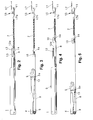
- the proposed device comprises ( figure 1 ) the existence in the device of a flexible brace (8) having an end attached to the swinging trigger (5) and, in a rear pulley (9), it forms a flat loop along which it extends rearwards in the rear pulley (9), leaves it forwards and it extends out of the frame (1) locating another end engaged to a removable carriage (10) being susceptible to receive the rear end of an independent tension spring (7) being located out of the frame (1) and having a forward end attached to an outer anchorage (11) being susceptible to be fixed along the guiding channel (2a) selectively.
- the frame (1) and other elements of the device allow the use of the tension spring (7) of different modules and/or sizes, due to the fact that the tension spring (7) is an independent element being located in the outer part of the frame (7), instead of along the guide-profile (2) which is conveniently chosen by only producing the outer anchorage fixing (11) therein; regarding this, according to the invention, the position of the outer anchorage (11) along the guiding channel (2a) is the function of the length and the tension of the tension spring (8).
- the above stated can be checked in the figure 1 regarding the possibility of that because of the functional combination of the rear pulley (9) and the kind of loop which the flexible brace makes over it.
- the flexible brace (8) has a band or strip shape.
- Another mode of execution comprises the flexible brace (8) having a thread shape.
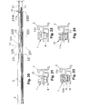
- the rear end of the flexible brace (8) is trapped by means of a rear clamp (13) being articulated with the appendix (5a) according to a turning axis perpendicular to the longitudinal middle plan of the swinging trigger (5); likewise, the forward end of the flexible brace (8) is trapped ( figures 1 and 13 ) by means of a forward clamp (14) incorporated into the removable carriage (10).
- the outer anchorage (11) comprises a fixing element (15) which allows the immobilization of said outer anchorage (11) in the desired point of the guiding channel (2a).
- the outer anchorage (11) has a fixing element (15) being quick by means of a lever (17) being articulated to the body of the outer anchorage (11) by means of an eccentric head (7a). This arrangement allows the fixation of the outer anchorage (11) in an easy and quick way along the guiding channel (2a), so avoiding the use of driving tools such as a screwdriver.
- FIG. 17 Another optional mode of execution ( figures 17 and 18 ) comprises a screw that, through the outer anchorage (11), is screwed in the plate (16) which, between the latter and the anchoring body (11), catch the opposing flanges of the guiding channel (2a).
- the end of the flexible brace (8) is attached to the swinging trigger (5) in a lower appendix (5a) of the swinging trigger (5), and the end of the flexible brace (8) is attached to the removable carriage (10) in a lower part of the removable carriage (10).
- the frame (1) in the forward end, opposed to the outer anchorage (11), the frame (1) has a forward protuberance (12) extending over the removable carriage (10) when this is in the coherent position with the closed sliding door (3); and, along its lower face, said forward protuberance (12) has a partition (12a) having an inverted T shape; and, at the same time, the removable carriage (10) ( figure 14 ) has in its upper face a rail (10b) having an inverted T shape which is reciprocal to the inverted T partition (12a) of the forward protuberance (12).
- a mode of execution comprises the forward protuberance (12) being a false element fixed to the frame (1) by screwing ( figure 20 ) or by another known technique.
- the removable carriage (10) ( figure 3 ) has both side grooves (10a) being complementary to the flanges of the guiding channel (2a).
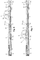
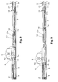
- Figure 6 is useful to depict a moment of the closing travel before reaching the swinging trigger (5), or a moment of the opening travel when the swinging trigger (5) has been already left.
- Figure 7 shows the precise moment when the side hook (6a) of the wheel (6), in the closing travel, has reached the position of the swinging trigger (5), not hooked yet, or the precise moment of the opening travel when the swinging trigger (5) is left.
- Figure 8 is a little later moment than the one in figure 7 during the closing or opening travels.
- Figure 9 is similar to the previous one, but showing the rail (10b) of the removable carriage (10) being engaged with the partition (12a) of the forward protuberance (12).
Landscapes
- Engineering & Computer Science (AREA)
- Mechanical Engineering (AREA)
- Support Devices For Sliding Doors (AREA)
- Rehabilitation Tools (AREA)
Applications Claiming Priority (1)
| Application Number | Priority Date | Filing Date | Title |
|---|---|---|---|
| ES201131208A ES2396084B1 (es) | 2011-07-15 | 2011-07-15 | Dispositivo de ayuda para el cierre de puertas correderas |
Publications (2)
| Publication Number | Publication Date |
|---|---|
| EP2546444A2 true EP2546444A2 (de) | 2013-01-16 |
| EP2546444A3 EP2546444A3 (de) | 2015-04-22 |
Family
ID=46826221
Family Applications (1)
| Application Number | Title | Priority Date | Filing Date |
|---|---|---|---|
| EP20120173957 Withdrawn EP2546444A3 (de) | 2011-07-15 | 2012-06-27 | Vorrichtung zur Unterstützung des Schließens von Schiebetüren |
Country Status (2)
| Country | Link |
|---|---|
| EP (1) | EP2546444A3 (de) |
| ES (1) | ES2396084B1 (de) |
Cited By (13)
| Publication number | Priority date | Publication date | Assignee | Title |
|---|---|---|---|---|
| CN104500127A (zh) * | 2014-12-19 | 2015-04-08 | 广东图特家居科技股份有限公司 | 一种隐藏式柜门缓冲器结构 |
| JP2015068065A (ja) * | 2013-09-30 | 2015-04-13 | 美和ロック株式会社 | 引戸の開閉装置 |
| CN104763261A (zh) * | 2015-03-26 | 2015-07-08 | 伍志勇 | 用于滑动门的阻尼按压反弹装置 |
| US20150204129A1 (en) * | 2012-07-12 | 2015-07-23 | Yoon Sig PARK | Automatic closing apparatus |
| CN105986720A (zh) * | 2015-03-17 | 2016-10-05 | 京特·齐默尔 | 组合的加速和减速装置的发动器 |
| US20160333622A1 (en) * | 2014-01-30 | 2016-11-17 | Komandor S.A. | Sliding door closing device |
| WO2017018890A1 (en) * | 2015-07-29 | 2017-02-02 | Assa Abloy New Zealand Limited | A closure mechanism |
| US9611684B2 (en) * | 2015-03-17 | 2017-04-04 | Guenther Zimmer | Sliding door |
| KR20180097308A (ko) * | 2017-02-23 | 2018-08-31 | (주)엘지하우시스 | 리프트 슬라이딩 창호용 안전감속장치 |
| KR20180097307A (ko) * | 2017-02-23 | 2018-08-31 | (주)엘지하우시스 | 도르래를 이용한 미서기 창호용 자동닫힘장치 |
| WO2018210901A1 (de) * | 2017-05-18 | 2018-11-22 | Hettich-Heinze Gmbh & Co. Kg | Möbel und verfahren zur montage eines schiebeelementes an einem möbelkorpus |
| CN109025604A (zh) * | 2018-09-18 | 2018-12-18 | 广东金利祥兴五金精密制造有限公司 | 一种移门缓冲器 |
| KR102327282B1 (ko) * | 2021-02-15 | 2021-11-16 | 김항수 | 슬라이딩 도어용 댐핑장치 |
Families Citing this family (1)
| Publication number | Priority date | Publication date | Assignee | Title |
|---|---|---|---|---|
| US20180016832A1 (en) * | 2015-09-21 | 2018-01-18 | Oscar RODRIGUEZ RODRIGUEZ | Soft-close system for sliding doors |
Family Cites Families (7)
| Publication number | Priority date | Publication date | Assignee | Title |
|---|---|---|---|---|
| TWI295335B (en) * | 2003-03-06 | 2008-04-01 | Howa Corp | Close device for sliding door |
| JP2006299578A (ja) * | 2005-04-19 | 2006-11-02 | Meiko:Kk | 引戸又は引出しの引込み装置 |
| JP4786944B2 (ja) * | 2005-06-15 | 2011-10-05 | 株式会社Lixil | 引戸の引き込み装置 |
| ITMI20072168A1 (it) * | 2007-11-14 | 2009-05-15 | Agostino Ferrari Spa | "sistema di chiusura controllata per elementi scorrevoli di mobilio" |
| DE102008021458A1 (de) * | 2008-04-29 | 2010-01-07 | Zimmer, Günther | Beschleunigungsvorrichtung mit zwei Energiespeichern |
| JP2010133221A (ja) * | 2008-10-29 | 2010-06-17 | Daiken Co Ltd | 引戸装置 |
| DE102009030272A1 (de) * | 2009-06-24 | 2010-12-30 | Daimler Ag | Tür |
-
2011
- 2011-07-15 ES ES201131208A patent/ES2396084B1/es not_active Expired - Fee Related
-
2012
- 2012-06-27 EP EP20120173957 patent/EP2546444A3/de not_active Withdrawn
Non-Patent Citations (1)
| Title |
|---|
| None |
Cited By (19)
| Publication number | Priority date | Publication date | Assignee | Title |
|---|---|---|---|---|
| US20150204129A1 (en) * | 2012-07-12 | 2015-07-23 | Yoon Sig PARK | Automatic closing apparatus |
| JP2015068065A (ja) * | 2013-09-30 | 2015-04-13 | 美和ロック株式会社 | 引戸の開閉装置 |
| US9708844B2 (en) * | 2014-01-30 | 2017-07-18 | Komandor S.A. | Sliding door closing device |
| US20160333622A1 (en) * | 2014-01-30 | 2016-11-17 | Komandor S.A. | Sliding door closing device |
| CN104500127B (zh) * | 2014-12-19 | 2017-09-08 | 广东图特家居科技股份有限公司 | 一种隐藏式柜门缓冲器结构 |
| CN104500127A (zh) * | 2014-12-19 | 2015-04-08 | 广东图特家居科技股份有限公司 | 一种隐藏式柜门缓冲器结构 |
| CN105986720A (zh) * | 2015-03-17 | 2016-10-05 | 京特·齐默尔 | 组合的加速和减速装置的发动器 |
| US9611684B2 (en) * | 2015-03-17 | 2017-04-04 | Guenther Zimmer | Sliding door |
| CN105986720B (zh) * | 2015-03-17 | 2018-06-05 | 京特·齐默尔 | 组合的加速和减速装置的发动器 |
| CN104763261A (zh) * | 2015-03-26 | 2015-07-08 | 伍志勇 | 用于滑动门的阻尼按压反弹装置 |
| WO2017018890A1 (en) * | 2015-07-29 | 2017-02-02 | Assa Abloy New Zealand Limited | A closure mechanism |
| US10513876B2 (en) | 2015-07-29 | 2019-12-24 | Assa Abloy New Zealand Limited | Closure mechanism |
| KR20180097308A (ko) * | 2017-02-23 | 2018-08-31 | (주)엘지하우시스 | 리프트 슬라이딩 창호용 안전감속장치 |
| KR20180097307A (ko) * | 2017-02-23 | 2018-08-31 | (주)엘지하우시스 | 도르래를 이용한 미서기 창호용 자동닫힘장치 |
| KR102083057B1 (ko) | 2017-02-23 | 2020-02-28 | (주)엘지하우시스 | 도르래를 이용한 미서기 창호용 자동닫힘장치 |
| WO2018210901A1 (de) * | 2017-05-18 | 2018-11-22 | Hettich-Heinze Gmbh & Co. Kg | Möbel und verfahren zur montage eines schiebeelementes an einem möbelkorpus |
| CN109025604A (zh) * | 2018-09-18 | 2018-12-18 | 广东金利祥兴五金精密制造有限公司 | 一种移门缓冲器 |
| CN109025604B (zh) * | 2018-09-18 | 2023-09-08 | 广东金利祥兴五金精密制造有限公司 | 一种移门缓冲器 |
| KR102327282B1 (ko) * | 2021-02-15 | 2021-11-16 | 김항수 | 슬라이딩 도어용 댐핑장치 |
Also Published As
| Publication number | Publication date |
|---|---|
| ES2396084R1 (es) | 2013-06-26 |
| ES2396084A2 (es) | 2013-02-19 |
| ES2396084B1 (es) | 2013-10-30 |
| EP2546444A3 (de) | 2015-04-22 |
Similar Documents
| Publication | Publication Date | Title |
|---|---|---|
| EP2546444A2 (de) | Vorrichtung zur Unterstützung des Schließens von Schiebetüren | |
| US8544209B2 (en) | Window lifter assembly | |
| CN110168181B (zh) | 滑动门配件 | |
| CA2664964C (en) | Reinforcing bar binding machine | |
| US8246102B2 (en) | Wide opening vehicle door with easy-reach feature | |
| CA2812931C (en) | Energy damper-storage device for low floor vehicle access ramp | |
| KR20150029604A (ko) | 가구용 감속 힌지 | |
| US10065554B1 (en) | Adjustable ratchet tie down | |
| CN105874140B (zh) | 用于推拉翼扇的终端位置拉入与终端位置缓冲装置 | |
| KR20160146883A (ko) | 차량의 폐쇄 요소를 위한 스프링 드라이브 | |
| FR2972209B1 (fr) | Element mobile de liaison de deux murs a coffrage integre et mur a coffrage integre comportant au moins un tel element mobile de liaison | |
| JP5716059B2 (ja) | 閉鎖補助装置 | |
| CN208190721U (zh) | 一种手机支架 | |
| EP2845758B1 (de) | Schiebedachvorrichtung für ein Fahrzeug | |
| KR102184819B1 (ko) | 미닫이용 완충장치 | |
| JP2012180640A (ja) | 折り畳みドアのアシスト装置 | |
| CA2775463C (en) | Self-closing device for sliding doors | |
| JP5588652B2 (ja) | 引き戸クローザ | |
| CN204610665U (zh) | 一种可调行程气弹簧结构及汽车后备箱盖自动升举装置 | |
| US20160347379A1 (en) | Tailgate counterbalance with dual torque rods | |
| CN213807218U (zh) | 联动机构及平趟门 | |
| CN222346720U (zh) | 一种用于车辆的遮阳帘 | |
| JPH0583260U (ja) | 引戸装置 | |
| EP1893446B1 (de) | Lastträger für festgelegte dachschiene | |
| CA2495344A1 (en) | Control pedal and assist mechanism |
Legal Events
| Date | Code | Title | Description |
|---|---|---|---|
| PUAI | Public reference made under article 153(3) epc to a published international application that has entered the european phase |
Free format text: ORIGINAL CODE: 0009012 |
|
| AK | Designated contracting states |
Kind code of ref document: A2 Designated state(s): AL AT BE BG CH CY CZ DE DK EE ES FI FR GB GR HR HU IE IS IT LI LT LU LV MC MK MT NL NO PL PT RO RS SE SI SK SM TR |
|
| AX | Request for extension of the european patent |
Extension state: BA ME |
|
| PUAL | Search report despatched |
Free format text: ORIGINAL CODE: 0009013 |
|
| AK | Designated contracting states |
Kind code of ref document: A3 Designated state(s): AL AT BE BG CH CY CZ DE DK EE ES FI FR GB GR HR HU IE IS IT LI LT LU LV MC MK MT NL NO PL PT RO RS SE SI SK SM TR |
|
| AX | Request for extension of the european patent |
Extension state: BA ME |
|
| RIC1 | Information provided on ipc code assigned before grant |
Ipc: E05F 1/16 20060101ALI20150313BHEP Ipc: E05F 5/00 20060101AFI20150313BHEP |
|
| STAA | Information on the status of an ep patent application or granted ep patent |
Free format text: STATUS: THE APPLICATION IS DEEMED TO BE WITHDRAWN |
|
| 18D | Application deemed to be withdrawn |
Effective date: 20151023 |