EP2546471A2 - Spitzenabstandssteuerung für Turbinenschaufeln - Google Patents
Spitzenabstandssteuerung für Turbinenschaufeln Download PDFInfo
- Publication number
- EP2546471A2 EP2546471A2 EP12175521A EP12175521A EP2546471A2 EP 2546471 A2 EP2546471 A2 EP 2546471A2 EP 12175521 A EP12175521 A EP 12175521A EP 12175521 A EP12175521 A EP 12175521A EP 2546471 A2 EP2546471 A2 EP 2546471A2
- Authority
- EP
- European Patent Office
- Prior art keywords
- inboard
- turbine casing
- casing
- duct
- outboard
- Prior art date
- Legal status (The legal status is an assumption and is not a legal conclusion. Google has not performed a legal analysis and makes no representation as to the accuracy of the status listed.)
- Granted
Links
Images


Classifications
-
- F—MECHANICAL ENGINEERING; LIGHTING; HEATING; WEAPONS; BLASTING
- F01—MACHINES OR ENGINES IN GENERAL; ENGINE PLANTS IN GENERAL; STEAM ENGINES
- F01D—NON-POSITIVE DISPLACEMENT MACHINES OR ENGINES, e.g. STEAM TURBINES
- F01D11/00—Preventing or minimising internal leakage of working-fluid, e.g. between stages
- F01D11/08—Preventing or minimising internal leakage of working-fluid, e.g. between stages for sealing space between rotor blade tips and stator
- F01D11/14—Adjusting or regulating tip-clearance, i.e. distance between rotor-blade tips and stator casing
- F01D11/20—Actively adjusting tip-clearance
- F01D11/24—Actively adjusting tip-clearance by selectively cooling-heating stator or rotor components
-
- F—MECHANICAL ENGINEERING; LIGHTING; HEATING; WEAPONS; BLASTING
- F01—MACHINES OR ENGINES IN GENERAL; ENGINE PLANTS IN GENERAL; STEAM ENGINES
- F01D—NON-POSITIVE DISPLACEMENT MACHINES OR ENGINES, e.g. STEAM TURBINES
- F01D25/00—Component parts, details, or accessories, not provided for in, or of interest apart from, other groups
- F01D25/08—Cooling; Heating; Heat-insulation
- F01D25/12—Cooling
-
- F—MECHANICAL ENGINEERING; LIGHTING; HEATING; WEAPONS; BLASTING
- F01—MACHINES OR ENGINES IN GENERAL; ENGINE PLANTS IN GENERAL; STEAM ENGINES
- F01D—NON-POSITIVE DISPLACEMENT MACHINES OR ENGINES, e.g. STEAM TURBINES
- F01D25/00—Component parts, details, or accessories, not provided for in, or of interest apart from, other groups
- F01D25/08—Cooling; Heating; Heat-insulation
- F01D25/14—Casings modified therefor
-
- F—MECHANICAL ENGINEERING; LIGHTING; HEATING; WEAPONS; BLASTING
- F01—MACHINES OR ENGINES IN GENERAL; ENGINE PLANTS IN GENERAL; STEAM ENGINES
- F01D—NON-POSITIVE DISPLACEMENT MACHINES OR ENGINES, e.g. STEAM TURBINES
- F01D25/00—Component parts, details, or accessories, not provided for in, or of interest apart from, other groups
- F01D25/08—Cooling; Heating; Heat-insulation
- F01D25/14—Casings modified therefor
- F01D25/145—Thermally insulated casings
-
- Y—GENERAL TAGGING OF NEW TECHNOLOGICAL DEVELOPMENTS; GENERAL TAGGING OF CROSS-SECTIONAL TECHNOLOGIES SPANNING OVER SEVERAL SECTIONS OF THE IPC; TECHNICAL SUBJECTS COVERED BY FORMER USPC CROSS-REFERENCE ART COLLECTIONS [XRACs] AND DIGESTS
- Y02—TECHNOLOGIES OR APPLICATIONS FOR MITIGATION OR ADAPTATION AGAINST CLIMATE CHANGE
- Y02T—CLIMATE CHANGE MITIGATION TECHNOLOGIES RELATED TO TRANSPORTATION
- Y02T50/00—Aeronautics or air transport
- Y02T50/60—Efficient propulsion technologies, e.g. for aircraft
Definitions
- the present invention relates to controlling the tip clearance of rotating blades within a gas turbine by controlling the temperature of the turbine casing.
- Modern gas turbine engines and more specifically turbofans for use in aviation, provide power by compressing air using a compressor, adding fuel to this compressed air, combusting this mixture such that it expands through the blades of a turbine and exhausting the produced gases.
- the turbine consists of a disc, rotating about the central shaft of the engine, and a plurality of blades extending radially out of the disc towards the engine casing of the engine. Expansion of the combustion gases through the turbine causes its blades to rotate at high speed and the turbine, in turn, drives the compressor.
- the distance between the tips of the blades and the inner surface of the turbine casing is known as the tip clearance. It is desirable for the tips of the turbine blades to rotate as close to the engine casing without rubbing as possible because as the tip clearance increases, a portion of the expanded gas flow will pass through the tip clearance the efficiency of the turbine decreases as. This is known as over-tip leakage.
- the efficiency of the turbine which partially depends upon tip clearance, directly affects the specific fuel consumption (SFC) of the engine. Accordingly, as tip clearance increases, SFC also rises.
- the turbine casing also expands as it is heated but there is typically a mismatch in radial expansion between the disc/blades and the casing. Specifically, the blades will normally expand radially more quickly than the housing, reducing the tip clearance and potentially leading to "rubbing" as the tips of blade come into contact with the interior of the casing of the turbine. Over time in use, the casing heats up and expands away from the blade tip, increasing the tip clearance. This may result in a tip clearance at stabilised cruise conditions that is larger than desired resulting in poor efficiency.
- tip clearances are set when the engine is cold to allow for radial extension of the turbine disc and blades due to centrifugal and thermal loads, to prevent rubbing. This means that there is initially a large tip clearance, such that the engine is relatively inefficient. When the engine is running, the blades will eventually extend radially to close this clearance, making the engine run more efficiently. Over a longer period of time, however, the temperature of the turbine casing will rise and the casing will expand radially, which will again increase the tip clearance.
- a general aim of aspects of the invention is to provide a more responsive arrangement for heating and cooling the turbine casing of a gas turbine engine.
- This heating and cooling causes the casing and associated components to expand and contract in the radial direction respectively to control the tip clearance of the rotating blades of the turbine. This makes it possible to maintain a minimal tip clearance whilst preventing rubbing of the blades against the turbine casing, even during transient operation, to maintain a relatively high level of efficiency.
- the invention provides an arrangement for heating and cooling a turbine casing of a gas turbine engine, the arrangement comprising an inboard duct, adjacent to an inboard surface of the turbine casing, an outboard facing wall of the inboard duct having a plurality of impingement holes opening towards the inboard surface of the casing, through which temperature control fluid can pass from within the inboard duct to impinge upon the inboard surface of the turbine casing.
- Inboard refers to a position that is radially closer to the axis of rotation on the turbine, whereas “outboard” refers to a position that is radially further from the axis of rotation of the turbine.
- the invention provides a method of radially expanding or contracting a turbine casing assembly, comprising impinging a temperature control fluid on the inboard surface of the turbine casing.
- the invention provides a method of radially expanding or contracting a turbine casing assembly, comprising passing a temperature control fluid through a plurality of impingement holes on the outboard facing wall of an inboard duct, the inboard duct being adjacent to the inboard surface of the turbine casing, such that the fluid impinges upon the inboard surface of the turbine casing, whereby the temperature change of the casing resulting from the impinging of the fluid causes the casing to expand or contract.
- the invention provides a turbine casing assembly, comprising the heating and cooling arrangement of the first aspect.
- the invention also provides a gas turbine engine comprising the turbine casing assembly of the fourth aspect.
- the temperature control fluid is a fluid that is capable of cooling and/or heating the turbine casing. It will typically be the working fluid of the gas turbine, e.g. air in a gas turbine for aircraft and air or a steam/air mixture in an industrial turbine. The air (or other working fluid) will normally be taken from the compressor stage of the engine.
- the temperature control fluid e.g. air
- the temperature control fluid may be taken from two or more locations in the engine, e.g. from two spaced apart locations in the compressor stage, at different temperatures and then mixed in selected proportions (or used alternately) to give a desired temperature for the fluid impinged on the turbine casing.
- the invention may additionally comprise an outboard duct, adjacent to the outboard surface of the turbine casing, the inboard facing wall of the outboard duct having a plurality of impingement holes opening towards the outboard surface of the casing, through which temperature control fluid (e.g. air) can pass from within the outboard duct to impinge upon the outboard surface of the turbine casing.
- the temperature control fluid may be from the same supply as the fluid supplied to the inboard duct.
- the outboard duct is supplied with cooler air (or other temperature control fluid) than the inboard duct.
- the cooler air may, for example, be from a lower pressure (and hence lower temperature) location in the engine than the location from which the supply of air to the inboard duct is taken. In this way, a desired temperature of the casing can be managed by controlling the relative flows of temperature control fluid to the inboard and outboard ducts.
- an inboard supply duct may be employed to deliver the temperature control fluid to the inboard duct.
- the turbine casing may also comprise an annular seal segment adjacent the blade tips inboard of the inboard duct, and a passage to direct a portion of the temperature control fluid after it has impinged on the turbine casing to subsequently impinge on the seal segment.
- the seal segment will generally be at a higher temperature than the turbine casing, although the temperature of the fluid will rise as it cools the turbine casing, it will still have the capacity to cool the seal segment.
- the turbine casing surfaces upon which the temperature control fluid impinges may be non-planar to increase the surface area against which the fluid impinges.
- the surfaces may comprise one or more ribs, fins, strips, grooves or other protrusions or recesses.
- the impingement holes may be angled to direct the temperature control fluid to impinge the turbine casing in a direction which is not perpendicular to the surface of the casing at the point at which the temperature control fluid strikes.
- the holes may be substantially circular, elliptical, elongate or any other of a number of suitable shapes.
- each duct comprising a plurality of radial impingement holes through which temperature control fluid can be impinged on the turbine casing.
- Figures 1 and 2 show a side and front elevation, respectively, of an arrangement in the turbine stage of a gas turbine engine for heating and cooling the turbine casing.
- the tip clearance of the turbine blades can be controlled to maintain a minimal gap, whilst avoiding rub.
- the combustion casing [1] is connected to the turbine casing [2] by a flanged joint.
- a seal segment [4] Inboard of the turbine casing, supported on a segment support ring [3], is a seal segment [4] that faces the tips of the rotating blades [11].
- the tip clearance [12] i.e. the gap between the tips of the blades [11] and the seal segment [4] should be as small as possible.
- a temperature control fluid is supplied to an annular inboard duct [6] within the turbine casing.
- the temperature control fluid is the working fluid of the gas turbine engine itself, specifically air taken from the compressor stage of the engine.
- the outboard facing wall [8] of the inboard duct [6] has a plurality of impingement holes [13], through which the temperature control fluid can pass, so as to impinge upon the inboard side of the turbine casing [2] in order to heat or cool the casing [2], dependent on whether the fluid is at a higher temperature or a lower temperature than the casing [2].
- the impingement flow [14] circulates around the outside of the inboard duct [6] to a cavity [7] between the inboard duct [5] and the seal segment [4]. In this way, the impingement flow [14] can also be used to cool the seal segment [4].
- the inboard surface of the turbine casing [2] is formed with longitudinal ribs [9] in order to increase the inboard surface area (most clearly shown in figure 2 ), and improve heat transfer between the impingement flow [14] and the turbine casing [2].
- the temperature control fluid is supplied via a supply duct [15] and may be obtained from one or more locations within the engine.
- the fluid may be obtained from areas of different temperatures within the engine, and mixed together in varying proportions to give a desired temperature.
- the fluid i.e. air
- the fluid is taken from the compressor stage of the engine.
- the turbine casing [2] assembly in this example also includes an outboard duct [16], around which the temperature control fluid also flows.
- the inboard facing wall [5] of the outboard duct [16] also contains a plurality of impingement holes [13], through which the temperature controlled fluid can pass, so as to impinge upon the turbine casing [2] in order to control its temperature, in a similar fashion to the inboard duct.
- the outboard surface of the turbine casing [2] is also formed with longitudinal ribs [10] to increase its surface area to aid heat transfer (most clearly shown in figure 2 ).
- the impingement holes [13] of the inboard [6] and/or outboard [16] duct may be angled such that the impingement flow [14] will strike the surface of turbine casing [2] obliquely. This will cause the impingement flow to circulate around the surface of the turbine casing [2] to improve heat transfer.
- the impingement holes [13] can be any of a number of suitable cross-sections including (for example, but not limited to) circular, elliptical, elongate, or as slot-shaped.
- the heating and cooling, and hence expansion and contraction of the turbine casing can be controlled in a more responsive manner, even during rapid acceleration or deceleration in transient manoeuvres.
- the enhanced cooling possible as a result of the features (e.g. ribs) on the surfaces of the turbine casing to increase its surface area also allow a reduction in tip clearance during cruise.
- thermodynamic analysis has shown that through a reduction in cold build tip clearance and increase contraction of the turbine casing through cooling (especially at cruise), a reduction in running clearance at cruise of up to 0.017" can be achieved, which equates to an improvement of about 1.7% SFC.
- FIGs 3 and 4 show a side and front elevation, respectively, of an arrangement in accordance with another embodiment of the invention.
- temperature control fluid e.g. air from a compressor stage of the engine
- temperature control fluid is impinged [14] through a plurality of impingement holes [13] spaced apart circumferentially and longitudinally on the surface of each inboard duct [6].
- each hole therefore impinges temperature control fluid at the inboard surface [18] of the turbine casing [2] at a range of angles of incidence to the casing [2] and this causes the fluid to circulate about the inboard surface [18] of the casing [2] [20] (most clearly seen in figure 4 ).
- the fluid is also subsequently used to cool the seal segment [4] by directing the fluid, after impingement on the turbine casing, between [21] the inboard ducts [6] to the seal segment cavity [7], as shown in figure 3 .
- an outboard duct [5] is located adjacent to the outboard surface [17] of the turbine casing [2], around which temperature control fluid can flow.
- the inboard facing wall [5] of the outboard duct [16] also contains a plurality of impingement holes [13], through which the temperature control fluid can pass, so as to impinge upon the turbine casing [2] in order to control its temperature.
- the outboard surface of the turbine casing [2] is also fitted with enhanced cooling features (in this case axial ribs [19]) to increase its wetted surface area to aid heat transfer.
- enhanced cooling features in this case axial ribs [19]
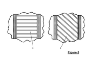
- Figure 5 shows two alternative plan views of the arrangement shown in figures 3 and 4 , clearly showing the radial arrangement of the inboard ducts [6].
Landscapes
- Engineering & Computer Science (AREA)
- Mechanical Engineering (AREA)
- General Engineering & Computer Science (AREA)
- Turbine Rotor Nozzle Sealing (AREA)
Applications Claiming Priority (1)
| Application Number | Priority Date | Filing Date | Title |
|---|---|---|---|
| GBGB1112163.9A GB201112163D0 (en) | 2011-07-15 | 2011-07-15 | Tip clearance control for turbine blades |
Publications (3)
| Publication Number | Publication Date |
|---|---|
| EP2546471A2 true EP2546471A2 (de) | 2013-01-16 |
| EP2546471A3 EP2546471A3 (de) | 2018-02-28 |
| EP2546471B1 EP2546471B1 (de) | 2019-03-06 |
Family
ID=44586638
Family Applications (1)
| Application Number | Title | Priority Date | Filing Date |
|---|---|---|---|
| EP12175521.9A Active EP2546471B1 (de) | 2011-07-15 | 2012-07-09 | Spitzenabstandssteuerung für Turbinenschaufeln |
Country Status (3)
| Country | Link |
|---|---|
| US (1) | US9506369B2 (de) |
| EP (1) | EP2546471B1 (de) |
| GB (1) | GB201112163D0 (de) |
Cited By (8)
| Publication number | Priority date | Publication date | Assignee | Title |
|---|---|---|---|---|
| FR3024751A1 (fr) * | 2014-08-05 | 2016-02-12 | Snecma | Unite de commande pour le pilotage d'un jeu entre des sommets d'aubes et un anneau de turbine |
| EP3091195A1 (de) * | 2015-05-08 | 2016-11-09 | General Electric Company | System und verfahren für abwärmebetriebene aktive abstandssteuerung |
| FR3040735A1 (fr) * | 2015-09-07 | 2017-03-10 | Snecma | Carter de turbine haute-pression d'une turbomachine a refroidissement localise |
| EP3219932A1 (de) * | 2016-03-16 | 2017-09-20 | United Technologies Corporation | Äussere laufschaufelluftdichtung mit strömungsführungsverteiler |
| US10119413B2 (en) | 2014-12-16 | 2018-11-06 | Rolls-Royce Plc | Tip clearance control for turbine blades |
| US10208617B2 (en) | 2014-12-16 | 2019-02-19 | Rolls-Royce Plc | Tip clearance control for turbine blades |
| FR3098549A1 (fr) * | 2019-07-11 | 2021-01-15 | Safran Aircraft Engines | Systeme de refroidissement pour carter de turbomachine |
| US10975721B2 (en) | 2016-01-12 | 2021-04-13 | Pratt & Whitney Canada Corp. | Cooled containment case using internal plenum |
Families Citing this family (14)
| Publication number | Priority date | Publication date | Assignee | Title |
|---|---|---|---|---|
| US20160047549A1 (en) * | 2014-08-15 | 2016-02-18 | Rolls-Royce Corporation | Ceramic matrix composite components with inserts |
| DE102015215144B4 (de) * | 2015-08-07 | 2017-11-09 | MTU Aero Engines AG | Vorrichtung und Verfahren zum Beeinflussen der Temperaturen in Innenringsegmenten einer Gasturbine |
| PL232314B1 (pl) * | 2016-05-06 | 2019-06-28 | Gen Electric | Maszyna przepływowa zawierająca system regulacji luzu |
| US10309246B2 (en) | 2016-06-07 | 2019-06-04 | General Electric Company | Passive clearance control system for gas turbomachine |
| US10392944B2 (en) | 2016-07-12 | 2019-08-27 | General Electric Company | Turbomachine component having impingement heat transfer feature, related turbomachine and storage medium |
| US10605093B2 (en) | 2016-07-12 | 2020-03-31 | General Electric Company | Heat transfer device and related turbine airfoil |
| US10577970B2 (en) * | 2016-09-13 | 2020-03-03 | Rolls-Royce North American Technologies Inc. | Turbine assembly with ceramic matrix composite blade track and actively cooled metallic carrier |
| CN107435563B (zh) * | 2017-05-05 | 2023-04-07 | 西北工业大学 | 一种具有叶尖间隙控制和叶顶流动控制的机匣结构 |
| GB201708746D0 (en) * | 2017-06-01 | 2017-07-19 | Rolls Royce Plc | Clearance control arrangement |
| US11242764B2 (en) * | 2018-05-17 | 2022-02-08 | Raytheon Technologies Corporation | Seal assembly with baffle for gas turbine engine |
| US11255214B2 (en) | 2019-11-04 | 2022-02-22 | Raytheon Technologies Corporation | Negative thermal expansion compressor case for improved tip clearance |
| US11566532B2 (en) * | 2020-12-04 | 2023-01-31 | Ge Avio S.R.L. | Turbine clearance control system |
| CN116085067A (zh) | 2021-11-05 | 2023-05-09 | 通用电气公司 | 具有流体导管系统的燃气涡轮发动机及其操作方法 |
| US11788425B2 (en) * | 2021-11-05 | 2023-10-17 | General Electric Company | Gas turbine engine with clearance control system |
Family Cites Families (6)
| Publication number | Priority date | Publication date | Assignee | Title |
|---|---|---|---|---|
| US4337016A (en) * | 1979-12-13 | 1982-06-29 | United Technologies Corporation | Dual wall seal means |
| GB2125111B (en) * | 1982-03-23 | 1985-06-05 | Rolls Royce | Shroud assembly for a gas turbine engine |
| US4524998A (en) * | 1982-05-04 | 1985-06-25 | Halliburton Company | Tubular connecting device |
| US4525998A (en) | 1982-08-02 | 1985-07-02 | United Technologies Corporation | Clearance control for gas turbine engine |
| US7914254B2 (en) * | 2007-02-13 | 2011-03-29 | General Electric Company | Integrated support/thermocouple housing for impingement cooling manifolds and cooling method |
| GB201004381D0 (en) * | 2010-03-17 | 2010-04-28 | Rolls Royce Plc | Rotor blade tip clearance control |
-
2011
- 2011-07-15 GB GBGB1112163.9A patent/GB201112163D0/en not_active Ceased
-
2012
- 2012-07-09 EP EP12175521.9A patent/EP2546471B1/de active Active
- 2012-07-09 US US13/544,211 patent/US9506369B2/en not_active Expired - Fee Related
Non-Patent Citations (1)
| Title |
|---|
| None |
Cited By (10)
| Publication number | Priority date | Publication date | Assignee | Title |
|---|---|---|---|---|
| FR3024751A1 (fr) * | 2014-08-05 | 2016-02-12 | Snecma | Unite de commande pour le pilotage d'un jeu entre des sommets d'aubes et un anneau de turbine |
| US10119413B2 (en) | 2014-12-16 | 2018-11-06 | Rolls-Royce Plc | Tip clearance control for turbine blades |
| US10208617B2 (en) | 2014-12-16 | 2019-02-19 | Rolls-Royce Plc | Tip clearance control for turbine blades |
| US10641122B2 (en) | 2014-12-16 | 2020-05-05 | Rolls-Royce Plc | Tip clearance control for turbine blades |
| EP3091195A1 (de) * | 2015-05-08 | 2016-11-09 | General Electric Company | System und verfahren für abwärmebetriebene aktive abstandssteuerung |
| FR3040735A1 (fr) * | 2015-09-07 | 2017-03-10 | Snecma | Carter de turbine haute-pression d'une turbomachine a refroidissement localise |
| US10975721B2 (en) | 2016-01-12 | 2021-04-13 | Pratt & Whitney Canada Corp. | Cooled containment case using internal plenum |
| EP3219932A1 (de) * | 2016-03-16 | 2017-09-20 | United Technologies Corporation | Äussere laufschaufelluftdichtung mit strömungsführungsverteiler |
| US10337346B2 (en) | 2016-03-16 | 2019-07-02 | United Technologies Corporation | Blade outer air seal with flow guide manifold |
| FR3098549A1 (fr) * | 2019-07-11 | 2021-01-15 | Safran Aircraft Engines | Systeme de refroidissement pour carter de turbomachine |
Also Published As
| Publication number | Publication date |
|---|---|
| GB201112163D0 (en) | 2011-08-31 |
| EP2546471A3 (de) | 2018-02-28 |
| EP2546471B1 (de) | 2019-03-06 |
| US20130017060A1 (en) | 2013-01-17 |
| US9506369B2 (en) | 2016-11-29 |
Similar Documents
| Publication | Publication Date | Title |
|---|---|---|
| US9506369B2 (en) | Tip clearance control for turbine blades | |
| US10316687B2 (en) | Blade track assembly with turbine tip clearance control | |
| US5022817A (en) | Thermostatic control of turbine cooling air | |
| JP5457965B2 (ja) | 回転機械におけるクリアランス制御用のシステム及び方法 | |
| US7269955B2 (en) | Methods and apparatus for maintaining rotor assembly tip clearances | |
| EP2375005B1 (de) | Verfahren zur steuerung des schaufelspitzendichtspalts einer turbine | |
| US9879544B2 (en) | Turbine rotor blades with improved tip portion cooling holes | |
| US10352329B2 (en) | Impeller shroud with thermal actuator for clearance control in a centrifugal compressor | |
| JPS6363721B2 (de) | ||
| US10641121B2 (en) | Gas turbine engine with rotor tip clearance control system | |
| EP3674521B1 (de) | Passives schaufelspitzenspielkontrollsystem für ein gasturbinentriebwerk | |
| US20080089783A1 (en) | Passive air seal clearance control | |
| JPS6325161B2 (de) | ||
| JP2006307853A (ja) | 軸流流体機械におけるラジアル隙間の調整方法と圧縮機 | |
| US20180298758A1 (en) | Method and system for cooling fluid distribution | |
| US10815884B2 (en) | Gas turbine engine de-icing system | |
| EP3118414B1 (de) | Gasturbinentriebwerksschaufel | |
| EP2948634B1 (de) | Gasturbinenmotorkomponente mit prallkühlung mittels einer abgewinkelten öffnung | |
| CN120100531A (zh) | 用于具有阻尼元件的发动机的开式风扇转子的可变节距翼型件组件 | |
| JP6775987B2 (ja) | タービン翼形部 | |
| US20150167488A1 (en) | Adjustable clearance control system for airfoil tip in gas turbine engine | |
| US20180216467A1 (en) | Turbine engine with an extension into a buffer cavity | |
| US10746033B2 (en) | Gas turbine engine component | |
| JPH06159099A (ja) | 軸流流体機械 | |
| WO2016068855A1 (en) | Active turbine blade tip clearance control system for turbine engines |
Legal Events
| Date | Code | Title | Description |
|---|---|---|---|
| PUAI | Public reference made under article 153(3) epc to a published international application that has entered the european phase |
Free format text: ORIGINAL CODE: 0009012 |
|
| AK | Designated contracting states |
Kind code of ref document: A2 Designated state(s): AL AT BE BG CH CY CZ DE DK EE ES FI FR GB GR HR HU IE IS IT LI LT LU LV MC MK MT NL NO PL PT RO RS SE SI SK SM TR |
|
| AX | Request for extension of the european patent |
Extension state: BA ME |
|
| RAP1 | Party data changed (applicant data changed or rights of an application transferred) |
Owner name: ROLLS-ROYCE PLC |
|
| PUAL | Search report despatched |
Free format text: ORIGINAL CODE: 0009013 |
|
| AK | Designated contracting states |
Kind code of ref document: A3 Designated state(s): AL AT BE BG CH CY CZ DE DK EE ES FI FR GB GR HR HU IE IS IT LI LT LU LV MC MK MT NL NO PL PT RO RS SE SI SK SM TR |
|
| AX | Request for extension of the european patent |
Extension state: BA ME |
|
| RIC1 | Information provided on ipc code assigned before grant |
Ipc: F01D 11/24 20060101AFI20180123BHEP Ipc: F01D 25/14 20060101ALI20180123BHEP Ipc: F01D 25/12 20060101ALI20180123BHEP |
|
| STAA | Information on the status of an ep patent application or granted ep patent |
Free format text: STATUS: REQUEST FOR EXAMINATION WAS MADE |
|
| 17P | Request for examination filed |
Effective date: 20180823 |
|
| RBV | Designated contracting states (corrected) |
Designated state(s): AL AT BE BG CH CY CZ DE DK EE ES FI FR GB GR HR HU IE IS IT LI LT LU LV MC MK MT NL NO PL PT RO RS SE SI SK SM TR |
|
| GRAP | Despatch of communication of intention to grant a patent |
Free format text: ORIGINAL CODE: EPIDOSNIGR1 |
|
| STAA | Information on the status of an ep patent application or granted ep patent |
Free format text: STATUS: GRANT OF PATENT IS INTENDED |
|
| GRAS | Grant fee paid |
Free format text: ORIGINAL CODE: EPIDOSNIGR3 |
|
| INTG | Intention to grant announced |
Effective date: 20190109 |
|
| GRAA | (expected) grant |
Free format text: ORIGINAL CODE: 0009210 |
|
| STAA | Information on the status of an ep patent application or granted ep patent |
Free format text: STATUS: THE PATENT HAS BEEN GRANTED |
|
| AK | Designated contracting states |
Kind code of ref document: B1 Designated state(s): AL AT BE BG CH CY CZ DE DK EE ES FI FR GB GR HR HU IE IS IT LI LT LU LV MC MK MT NL NO PL PT RO RS SE SI SK SM TR |
|
| REG | Reference to a national code |
Ref country code: GB Ref legal event code: FG4D |
|
| REG | Reference to a national code |
Ref country code: CH Ref legal event code: EP Ref country code: AT Ref legal event code: REF Ref document number: 1104822 Country of ref document: AT Kind code of ref document: T Effective date: 20190315 |
|
| REG | Reference to a national code |
Ref country code: DE Ref legal event code: R096 Ref document number: 602012057371 Country of ref document: DE |
|
| REG | Reference to a national code |
Ref country code: IE Ref legal event code: FG4D |
|
| REG | Reference to a national code |
Ref country code: NL Ref legal event code: MP Effective date: 20190306 |
|
| REG | Reference to a national code |
Ref country code: LT Ref legal event code: MG4D |
|
| PG25 | Lapsed in a contracting state [announced via postgrant information from national office to epo] |
Ref country code: SE Free format text: LAPSE BECAUSE OF FAILURE TO SUBMIT A TRANSLATION OF THE DESCRIPTION OR TO PAY THE FEE WITHIN THE PRESCRIBED TIME-LIMIT Effective date: 20190306 Ref country code: NO Free format text: LAPSE BECAUSE OF FAILURE TO SUBMIT A TRANSLATION OF THE DESCRIPTION OR TO PAY THE FEE WITHIN THE PRESCRIBED TIME-LIMIT Effective date: 20190606 Ref country code: FI Free format text: LAPSE BECAUSE OF FAILURE TO SUBMIT A TRANSLATION OF THE DESCRIPTION OR TO PAY THE FEE WITHIN THE PRESCRIBED TIME-LIMIT Effective date: 20190306 Ref country code: LT Free format text: LAPSE BECAUSE OF FAILURE TO SUBMIT A TRANSLATION OF THE DESCRIPTION OR TO PAY THE FEE WITHIN THE PRESCRIBED TIME-LIMIT Effective date: 20190306 |
|
| PG25 | Lapsed in a contracting state [announced via postgrant information from national office to epo] |
Ref country code: GR Free format text: LAPSE BECAUSE OF FAILURE TO SUBMIT A TRANSLATION OF THE DESCRIPTION OR TO PAY THE FEE WITHIN THE PRESCRIBED TIME-LIMIT Effective date: 20190607 Ref country code: HR Free format text: LAPSE BECAUSE OF FAILURE TO SUBMIT A TRANSLATION OF THE DESCRIPTION OR TO PAY THE FEE WITHIN THE PRESCRIBED TIME-LIMIT Effective date: 20190306 Ref country code: NL Free format text: LAPSE BECAUSE OF FAILURE TO SUBMIT A TRANSLATION OF THE DESCRIPTION OR TO PAY THE FEE WITHIN THE PRESCRIBED TIME-LIMIT Effective date: 20190306 Ref country code: LV Free format text: LAPSE BECAUSE OF FAILURE TO SUBMIT A TRANSLATION OF THE DESCRIPTION OR TO PAY THE FEE WITHIN THE PRESCRIBED TIME-LIMIT Effective date: 20190306 Ref country code: RS Free format text: LAPSE BECAUSE OF FAILURE TO SUBMIT A TRANSLATION OF THE DESCRIPTION OR TO PAY THE FEE WITHIN THE PRESCRIBED TIME-LIMIT Effective date: 20190306 Ref country code: BG Free format text: LAPSE BECAUSE OF FAILURE TO SUBMIT A TRANSLATION OF THE DESCRIPTION OR TO PAY THE FEE WITHIN THE PRESCRIBED TIME-LIMIT Effective date: 20190606 |
|
| REG | Reference to a national code |
Ref country code: AT Ref legal event code: MK05 Ref document number: 1104822 Country of ref document: AT Kind code of ref document: T Effective date: 20190306 |
|
| PG25 | Lapsed in a contracting state [announced via postgrant information from national office to epo] |
Ref country code: RO Free format text: LAPSE BECAUSE OF FAILURE TO SUBMIT A TRANSLATION OF THE DESCRIPTION OR TO PAY THE FEE WITHIN THE PRESCRIBED TIME-LIMIT Effective date: 20190306 Ref country code: IT Free format text: LAPSE BECAUSE OF FAILURE TO SUBMIT A TRANSLATION OF THE DESCRIPTION OR TO PAY THE FEE WITHIN THE PRESCRIBED TIME-LIMIT Effective date: 20190306 Ref country code: CZ Free format text: LAPSE BECAUSE OF FAILURE TO SUBMIT A TRANSLATION OF THE DESCRIPTION OR TO PAY THE FEE WITHIN THE PRESCRIBED TIME-LIMIT Effective date: 20190306 Ref country code: EE Free format text: LAPSE BECAUSE OF FAILURE TO SUBMIT A TRANSLATION OF THE DESCRIPTION OR TO PAY THE FEE WITHIN THE PRESCRIBED TIME-LIMIT Effective date: 20190306 Ref country code: ES Free format text: LAPSE BECAUSE OF FAILURE TO SUBMIT A TRANSLATION OF THE DESCRIPTION OR TO PAY THE FEE WITHIN THE PRESCRIBED TIME-LIMIT Effective date: 20190306 Ref country code: AL Free format text: LAPSE BECAUSE OF FAILURE TO SUBMIT A TRANSLATION OF THE DESCRIPTION OR TO PAY THE FEE WITHIN THE PRESCRIBED TIME-LIMIT Effective date: 20190306 Ref country code: PT Free format text: LAPSE BECAUSE OF FAILURE TO SUBMIT A TRANSLATION OF THE DESCRIPTION OR TO PAY THE FEE WITHIN THE PRESCRIBED TIME-LIMIT Effective date: 20190706 Ref country code: SK Free format text: LAPSE BECAUSE OF FAILURE TO SUBMIT A TRANSLATION OF THE DESCRIPTION OR TO PAY THE FEE WITHIN THE PRESCRIBED TIME-LIMIT Effective date: 20190306 |
|
| PG25 | Lapsed in a contracting state [announced via postgrant information from national office to epo] |
Ref country code: PL Free format text: LAPSE BECAUSE OF FAILURE TO SUBMIT A TRANSLATION OF THE DESCRIPTION OR TO PAY THE FEE WITHIN THE PRESCRIBED TIME-LIMIT Effective date: 20190306 Ref country code: SM Free format text: LAPSE BECAUSE OF FAILURE TO SUBMIT A TRANSLATION OF THE DESCRIPTION OR TO PAY THE FEE WITHIN THE PRESCRIBED TIME-LIMIT Effective date: 20190306 |
|
| REG | Reference to a national code |
Ref country code: DE Ref legal event code: R097 Ref document number: 602012057371 Country of ref document: DE |
|
| PG25 | Lapsed in a contracting state [announced via postgrant information from national office to epo] |
Ref country code: AT Free format text: LAPSE BECAUSE OF FAILURE TO SUBMIT A TRANSLATION OF THE DESCRIPTION OR TO PAY THE FEE WITHIN THE PRESCRIBED TIME-LIMIT Effective date: 20190306 Ref country code: IS Free format text: LAPSE BECAUSE OF FAILURE TO SUBMIT A TRANSLATION OF THE DESCRIPTION OR TO PAY THE FEE WITHIN THE PRESCRIBED TIME-LIMIT Effective date: 20190706 |
|
| PLBE | No opposition filed within time limit |
Free format text: ORIGINAL CODE: 0009261 |
|
| STAA | Information on the status of an ep patent application or granted ep patent |
Free format text: STATUS: NO OPPOSITION FILED WITHIN TIME LIMIT |
|
| PG25 | Lapsed in a contracting state [announced via postgrant information from national office to epo] |
Ref country code: DK Free format text: LAPSE BECAUSE OF FAILURE TO SUBMIT A TRANSLATION OF THE DESCRIPTION OR TO PAY THE FEE WITHIN THE PRESCRIBED TIME-LIMIT Effective date: 20190306 |
|
| 26N | No opposition filed |
Effective date: 20191209 |
|
| PG25 | Lapsed in a contracting state [announced via postgrant information from national office to epo] |
Ref country code: SI Free format text: LAPSE BECAUSE OF FAILURE TO SUBMIT A TRANSLATION OF THE DESCRIPTION OR TO PAY THE FEE WITHIN THE PRESCRIBED TIME-LIMIT Effective date: 20190306 Ref country code: MC Free format text: LAPSE BECAUSE OF FAILURE TO SUBMIT A TRANSLATION OF THE DESCRIPTION OR TO PAY THE FEE WITHIN THE PRESCRIBED TIME-LIMIT Effective date: 20190306 |
|
| REG | Reference to a national code |
Ref country code: CH Ref legal event code: PL |
|
| PG25 | Lapsed in a contracting state [announced via postgrant information from national office to epo] |
Ref country code: TR Free format text: LAPSE BECAUSE OF FAILURE TO SUBMIT A TRANSLATION OF THE DESCRIPTION OR TO PAY THE FEE WITHIN THE PRESCRIBED TIME-LIMIT Effective date: 20190306 |
|
| REG | Reference to a national code |
Ref country code: BE Ref legal event code: MM Effective date: 20190731 |
|
| PG25 | Lapsed in a contracting state [announced via postgrant information from national office to epo] |
Ref country code: LI Free format text: LAPSE BECAUSE OF NON-PAYMENT OF DUE FEES Effective date: 20190731 Ref country code: CH Free format text: LAPSE BECAUSE OF NON-PAYMENT OF DUE FEES Effective date: 20190731 Ref country code: BE Free format text: LAPSE BECAUSE OF NON-PAYMENT OF DUE FEES Effective date: 20190731 Ref country code: LU Free format text: LAPSE BECAUSE OF NON-PAYMENT OF DUE FEES Effective date: 20190709 |
|
| PG25 | Lapsed in a contracting state [announced via postgrant information from national office to epo] |
Ref country code: IE Free format text: LAPSE BECAUSE OF NON-PAYMENT OF DUE FEES Effective date: 20190709 |
|
| PG25 | Lapsed in a contracting state [announced via postgrant information from national office to epo] |
Ref country code: CY Free format text: LAPSE BECAUSE OF FAILURE TO SUBMIT A TRANSLATION OF THE DESCRIPTION OR TO PAY THE FEE WITHIN THE PRESCRIBED TIME-LIMIT Effective date: 20190306 |
|
| PG25 | Lapsed in a contracting state [announced via postgrant information from national office to epo] |
Ref country code: MT Free format text: LAPSE BECAUSE OF FAILURE TO SUBMIT A TRANSLATION OF THE DESCRIPTION OR TO PAY THE FEE WITHIN THE PRESCRIBED TIME-LIMIT Effective date: 20190306 Ref country code: HU Free format text: LAPSE BECAUSE OF FAILURE TO SUBMIT A TRANSLATION OF THE DESCRIPTION OR TO PAY THE FEE WITHIN THE PRESCRIBED TIME-LIMIT; INVALID AB INITIO Effective date: 20120709 |
|
| PG25 | Lapsed in a contracting state [announced via postgrant information from national office to epo] |
Ref country code: MK Free format text: LAPSE BECAUSE OF FAILURE TO SUBMIT A TRANSLATION OF THE DESCRIPTION OR TO PAY THE FEE WITHIN THE PRESCRIBED TIME-LIMIT Effective date: 20190306 |
|
| P01 | Opt-out of the competence of the unified patent court (upc) registered |
Effective date: 20230528 |
|
| PGFP | Annual fee paid to national office [announced via postgrant information from national office to epo] |
Ref country code: DE Payment date: 20250728 Year of fee payment: 14 |
|
| PGFP | Annual fee paid to national office [announced via postgrant information from national office to epo] |
Ref country code: GB Payment date: 20250722 Year of fee payment: 14 |
|
| PGFP | Annual fee paid to national office [announced via postgrant information from national office to epo] |
Ref country code: FR Payment date: 20250725 Year of fee payment: 14 |