EP2546483A1 - Système de traitement de gaz d'échappement pour moteur - Google Patents
Système de traitement de gaz d'échappement pour moteur Download PDFInfo
- Publication number
- EP2546483A1 EP2546483A1 EP11753147A EP11753147A EP2546483A1 EP 2546483 A1 EP2546483 A1 EP 2546483A1 EP 11753147 A EP11753147 A EP 11753147A EP 11753147 A EP11753147 A EP 11753147A EP 2546483 A1 EP2546483 A1 EP 2546483A1
- Authority
- EP
- European Patent Office
- Prior art keywords
- engine speed
- exhaust gas
- regeneration
- temperature
- rotation speed
- Prior art date
- Legal status (The legal status is an assumption and is not a legal conclusion. Google has not performed a legal analysis and makes no representation as to the accuracy of the status listed.)
- Granted
Links
Images


Classifications
-
- F—MECHANICAL ENGINEERING; LIGHTING; HEATING; WEAPONS; BLASTING
- F01—MACHINES OR ENGINES IN GENERAL; ENGINE PLANTS IN GENERAL; STEAM ENGINES
- F01N—GAS-FLOW SILENCERS OR EXHAUST APPARATUS FOR MACHINES OR ENGINES IN GENERAL; GAS-FLOW SILENCERS OR EXHAUST APPARATUS FOR INTERNAL-COMBUSTION ENGINES
- F01N3/00—Exhaust or silencing apparatus having means for purifying, rendering innocuous, or otherwise treating exhaust
- F01N3/02—Exhaust or silencing apparatus having means for purifying, rendering innocuous, or otherwise treating exhaust for cooling, or for removing solid constituents of, exhaust
- F01N3/021—Exhaust or silencing apparatus having means for purifying, rendering innocuous, or otherwise treating exhaust for cooling, or for removing solid constituents of, exhaust by means of filters
- F01N3/023—Exhaust or silencing apparatus having means for purifying, rendering innocuous, or otherwise treating exhaust for cooling, or for removing solid constituents of, exhaust by means of filters using means for regenerating the filters, e.g. by burning trapped particles
-
- F—MECHANICAL ENGINEERING; LIGHTING; HEATING; WEAPONS; BLASTING
- F02—COMBUSTION ENGINES; HOT-GAS OR COMBUSTION-PRODUCT ENGINE PLANTS
- F02D—CONTROLLING COMBUSTION ENGINES
- F02D31/00—Use of speed-sensing governors to control combustion engines, not otherwise provided for
- F02D31/001—Electric control of rotation speed
- F02D31/007—Electric control of rotation speed controlling fuel supply
-
- F—MECHANICAL ENGINEERING; LIGHTING; HEATING; WEAPONS; BLASTING
- F02—COMBUSTION ENGINES; HOT-GAS OR COMBUSTION-PRODUCT ENGINE PLANTS
- F02D—CONTROLLING COMBUSTION ENGINES
- F02D41/00—Electrical control of supply of combustible mixture or its constituents
- F02D41/02—Circuit arrangements for generating control signals
- F02D41/0205—Circuit arrangements for generating control signals using an auxiliary engine speed control
-
- F—MECHANICAL ENGINEERING; LIGHTING; HEATING; WEAPONS; BLASTING
- F02—COMBUSTION ENGINES; HOT-GAS OR COMBUSTION-PRODUCT ENGINE PLANTS
- F02D—CONTROLLING COMBUSTION ENGINES
- F02D41/00—Electrical control of supply of combustible mixture or its constituents
- F02D41/02—Circuit arrangements for generating control signals
- F02D41/021—Introducing corrections for particular conditions exterior to the engine
- F02D41/0235—Introducing corrections for particular conditions exterior to the engine in relation with the state of the exhaust gas treating apparatus
- F02D41/024—Introducing corrections for particular conditions exterior to the engine in relation with the state of the exhaust gas treating apparatus to increase temperature of the exhaust gas treating apparatus
- F02D41/0245—Introducing corrections for particular conditions exterior to the engine in relation with the state of the exhaust gas treating apparatus to increase temperature of the exhaust gas treating apparatus by increasing temperature of the exhaust gas leaving the engine
-
- F—MECHANICAL ENGINEERING; LIGHTING; HEATING; WEAPONS; BLASTING
- F02—COMBUSTION ENGINES; HOT-GAS OR COMBUSTION-PRODUCT ENGINE PLANTS
- F02D—CONTROLLING COMBUSTION ENGINES
- F02D41/00—Electrical control of supply of combustible mixture or its constituents
- F02D41/02—Circuit arrangements for generating control signals
- F02D41/021—Introducing corrections for particular conditions exterior to the engine
- F02D41/0235—Introducing corrections for particular conditions exterior to the engine in relation with the state of the exhaust gas treating apparatus
- F02D41/027—Introducing corrections for particular conditions exterior to the engine in relation with the state of the exhaust gas treating apparatus to purge or regenerate the exhaust gas treating apparatus
- F02D41/029—Introducing corrections for particular conditions exterior to the engine in relation with the state of the exhaust gas treating apparatus to purge or regenerate the exhaust gas treating apparatus the exhaust gas treating apparatus being a particulate filter
-
- F—MECHANICAL ENGINEERING; LIGHTING; HEATING; WEAPONS; BLASTING
- F01—MACHINES OR ENGINES IN GENERAL; ENGINE PLANTS IN GENERAL; STEAM ENGINES
- F01N—GAS-FLOW SILENCERS OR EXHAUST APPARATUS FOR MACHINES OR ENGINES IN GENERAL; GAS-FLOW SILENCERS OR EXHAUST APPARATUS FOR INTERNAL-COMBUSTION ENGINES
- F01N2430/00—Influencing exhaust purification, e.g. starting of catalytic reaction, filter regeneration, or the like, by controlling engine operating characteristics
-
- F—MECHANICAL ENGINEERING; LIGHTING; HEATING; WEAPONS; BLASTING
- F01—MACHINES OR ENGINES IN GENERAL; ENGINE PLANTS IN GENERAL; STEAM ENGINES
- F01N—GAS-FLOW SILENCERS OR EXHAUST APPARATUS FOR MACHINES OR ENGINES IN GENERAL; GAS-FLOW SILENCERS OR EXHAUST APPARATUS FOR INTERNAL-COMBUSTION ENGINES
- F01N2560/00—Exhaust systems with means for detecting or measuring exhaust gas components or characteristics
- F01N2560/06—Exhaust systems with means for detecting or measuring exhaust gas components or characteristics the means being a temperature sensor
-
- F—MECHANICAL ENGINEERING; LIGHTING; HEATING; WEAPONS; BLASTING
- F01—MACHINES OR ENGINES IN GENERAL; ENGINE PLANTS IN GENERAL; STEAM ENGINES
- F01N—GAS-FLOW SILENCERS OR EXHAUST APPARATUS FOR MACHINES OR ENGINES IN GENERAL; GAS-FLOW SILENCERS OR EXHAUST APPARATUS FOR INTERNAL-COMBUSTION ENGINES
- F01N9/00—Electrical control of exhaust gas treating apparatus
- F01N9/002—Electrical control of exhaust gas treating apparatus of filter regeneration
-
- F—MECHANICAL ENGINEERING; LIGHTING; HEATING; WEAPONS; BLASTING
- F02—COMBUSTION ENGINES; HOT-GAS OR COMBUSTION-PRODUCT ENGINE PLANTS
- F02D—CONTROLLING COMBUSTION ENGINES
- F02D2200/00—Input parameters for engine control
- F02D2200/60—Input parameters for engine control said parameters being related to the driver demands or status
- F02D2200/604—Engine control mode selected by driver, e.g. to manually start particle filter regeneration or to select driving style
-
- F—MECHANICAL ENGINEERING; LIGHTING; HEATING; WEAPONS; BLASTING
- F02—COMBUSTION ENGINES; HOT-GAS OR COMBUSTION-PRODUCT ENGINE PLANTS
- F02D—CONTROLLING COMBUSTION ENGINES
- F02D41/00—Electrical control of supply of combustible mixture or its constituents
- F02D41/02—Circuit arrangements for generating control signals
- F02D41/14—Introducing closed-loop corrections
- F02D41/1438—Introducing closed-loop corrections using means for determining characteristics of the combustion gases; Sensors therefor
- F02D41/1444—Introducing closed-loop corrections using means for determining characteristics of the combustion gases; Sensors therefor characterised by the characteristics of the combustion gases
- F02D41/1446—Introducing closed-loop corrections using means for determining characteristics of the combustion gases; Sensors therefor characterised by the characteristics of the combustion gases the characteristics being exhaust temperatures
-
- Y—GENERAL TAGGING OF NEW TECHNOLOGICAL DEVELOPMENTS; GENERAL TAGGING OF CROSS-SECTIONAL TECHNOLOGIES SPANNING OVER SEVERAL SECTIONS OF THE IPC; TECHNICAL SUBJECTS COVERED BY FORMER USPC CROSS-REFERENCE ART COLLECTIONS [XRACs] AND DIGESTS
- Y02—TECHNOLOGIES OR APPLICATIONS FOR MITIGATION OR ADAPTATION AGAINST CLIMATE CHANGE
- Y02T—CLIMATE CHANGE MITIGATION TECHNOLOGIES RELATED TO TRANSPORTATION
- Y02T10/00—Road transport of goods or passengers
- Y02T10/10—Internal combustion engine [ICE] based vehicles
- Y02T10/12—Improving ICE efficiencies
Definitions
- the present invention relates to an exhaust gas processing system.
- the temperature of the exhaust gas When the temperature of the exhaust gas is higher than regeneration temperature of the DPF, the PM collected in the DPF can be made harmless and removed. On the other hand, when the temperature of the exhaust gas is lower than regeneration temperature of the DPF, the PM collected in the DPF cannot be made harmless and removed. Then, in this case, as regeneration control of the DPF, the temperature of the exhaust gas must be made higher than the regeneration temperature regularly by using EGR and exhaust gas with excessive fuel so as to make the PM collected in the DPF harmless and remove it.
- the Japanese Patent Laid Open Gazette 2004-183506 discloses construction in which, in the case of manual regeneration control of a DPF for exhaust gas, engine speed is increased to a predetermined value so as to make the temperature of the exhaust gas is higher than regeneration temperature of the DPF.
- the manual regeneration control is regeneration control performed based on certain manual operation by an operator.
- the purpose of the present invention is to provide an exhaust gas processing system performing manual regeneration control regenerating a particulate removing filter by increasing engine speed which can suppress increase of engine speed while securing regeneration temperature required for regeneration of a particulate removing filter.
- a filter removing particulate in exhaust gas is provided in an exhaust passage, an exhaust gas temperature sensor detecting exhaust gas temperature is provided upstream the filter, a manual regeneration means commanding regeneration of the filter, and a target engine speed is set be a first set value when a regeneration command signal from the manual regeneration means is received.
- the target engine speed is set be a value increased for a predetermined engine speed from the first set value, and after this, when the exhaust gas temperature does not reach the regeneration temperature of the filter until the predetermined time passes after the engine speed remains in a predetermined range of engine speed including the reset set value, the target engine speed is set be a value increased for the predetermined engine speed from the actual engine speed, and repeats this control.
- the exhaust gas processing system of the present invention in the manual regeneration control regenerating the particulate removing filter by increasing the engine speed, the increase of the engine speed can be suppressed while securing regeneration temperature required for the regeneration of the particulate removing filter
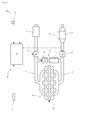
- the engine 100 includes a four-cylindered engine body 11, an intake route 12, an exhaust route 13, an EGR route 14, a regeneration switch 70 as a manual regeneration means, a fuel injection device 80 and an ECU (Engine Control Unit) 50.
- the intake route 12 is connected to an intake manifold of the engine body 11, and has an air cleaner 25 and an intake throttle 20.
- the intake throttle 20 is arranged downstream the air cleaner 25 in the intake route 12.
- the exhaust route 13 is connected to an exhaust manifold of the engine body 11, and has an exhaust throttle 30 and a DPF (Diesel Particulate Filter) 35 as a particulate removing filter.
- the exhaust throttle 30 is arranged upstream the DPF 35 in the exhaust route 13.
- the EGR route 14 is connected to the part of the intake route 12 downstream the intake throttle 20 and connected to the part of the exhaust route 13 upstream the exhaust throttle 30, and has an EGR valve 40 and an EGR cooler 45.
- the ECU 50 is a control means of the engine 100 and is connected to the intake throttle 20, the exhaust throttle 30, the EGR valve 40, an engine speed sensor 61, an exhaust gas temperature sensor 62, the regeneration switch 70 as the manual regeneration means, and the fuel injection device 80.
- the ECU 50 controls fuel injection of the fuel injection device 80 so as to make an engine speed Ne become a target engine speed Nem, thereby controlling the engine speed Ne.
- the target engine speed Nem is set with a target engine speed setting means, for example an accelerator lever.
- the regeneration switch 70 is arranged as a manual switch near an operation panel of an operator's seat. Before work with the working vehicle, an operator turns the regeneration switch 70 on so as to regenerate the DPF 35 manually.
- the exhaust gas processing system 10 includes the ECU 50, the exhaust gas temperature sensor 62, the regeneration switch 70 and the fuel injection device 80, and performs regeneration control which raises exhaust gas temperature so as to make harmless PM (Particulate matters) collected in the DPF 35 and remove them when the exhaust gas temperature is lower than a regeneration temperature Th1 required for the regeneration of the DPF 35.
- the exhaust gas processing system 10 in this embodiment performs manual regeneration control as discussed below. Namely, in the case of receiving a regeneration command signal, when the exhaust gas temperature is lower than the regeneration temperature Th1, the engine speed Ne is increased so as to raise the exhaust gas temperature The not less than the regeneration temperature Th1.
- the ECU 50 performs below manual regeneration control.
- the ECU 50 makes the target engine speed Nem be a first set value Ne1 set previously so as to control the engine speed Ne.
- the first set value Ne1 is a low idling speed of the engine 100.
- the ECU 50 confirms whether the engine speed Ne converges at the target engine speed Nem or not.
- the control shifts to a step S130.
- Convergence at the target engine speed Nem means the state in which the engine speed Ne remains in a predetermined range of engine speed including the target engine speed Nem for a predetermined time.
- the ECU 50 confirms whether an exhaust temperature monitoring time t2 passes after the engine speed Ne converges at the target engine speed Nem or not.
- the control shifts to a step S140.
- the exhaust temperature monitoring time t2 is previously set and stored in the ECU 50, and enough longer than a time for increasing the engine speed Ne for a predetermined engine speed ⁇ Ne (t1 ion Fig. 3 ).
- the ECU 50 confirms whether the exhaust gas temperature The reaches the regeneration temperature Th1 required for the regeneration of the DPF 35 or not.
- the control shifts to a step S150.
- the exhaust gas temperature The reaches the regeneration temperature Th1
- the actual target engine speed Nem is maintained.
- the regeneration temperature Th1 is previously stored in the ECU 50, and is the temperature which can make the PM collected in the DPF 35 harmless and remove it.
- the ECU 50 changes the target engine speed Nem from the actual value to the value increasing the first set value Ne1 for the predetermined engine speed ⁇ Ne, and the control shifts to the step S120 again.
- the predetermined engine speed ⁇ Ne is previously set optionally and stored in the ECU 50.
- Fig. 3 shows the time series variation of the engine speed Ne.
- the behavior of the engine speed Ne is described below following the time series (points A to E passing successively).
- the target engine speed Nem is set be the first set value Ne1.
- the engine speed Ne is controlled to converge at the first set value Ne1.
- the target engine speed Nem set be the value increased for the predetermined engine speed ⁇ Ne from the first set value Ne1 which is the actual value.
- the engine speed Ne is controlled to converge at the reset target engine speed Nem(Ne1+ ⁇ Ne).
- the target engine speed Nem set be the value increased for the predetermined engine speed ⁇ Ne from the target engine speed Nem(Ne1+ ⁇ Ne) which is the actual value.
- the engine speed Ne is controlled to converge at the target engine speed Nem(Ne1+2 ⁇ Ne). After this, the same control from the point D to the point E is repeated until the exhaust gas temperature The reaches the regeneration temperature Th1.
- the target engine speed Nem is set be the value increased for the predetermined engine speed from the first set value Ne1. Then, when the exhaust gas temperature The does not reach the regeneration temperature Th1 of the DPF 35 until the predetermined time passes after the engine speed Ne converges at the reset target engine speed Nem(Ne1+ ⁇ Ne), the target engine speed Nem is set be the value increased for the predetermined engine speed from the actual engine speed Nem(Ne1+ ⁇ Ne) and repeats this control.
- the exhaust gas temperature The is monitored, and when the exhaust gas temperature The does not reach the regeneration temperature Th1, the target engine speed Nem is increased for the predetermined engine speed ⁇ Ne for each passing of the exhaust temperature monitoring time t2 by stages, for example the target engine speed Nem(Ne1+ ⁇ Ne), the target engine speed Nem(Ne1+2 ⁇ Ne), the target engine speed Nem(Ne1+3 ⁇ Ne), and the target engine speed Nem(Ne1+4 ⁇ Ne), whereby the exhaust gas temperature The is raised so as to reach the regeneration temperature Th1. Therefore, excessive increase of the engine speed Ne can be suppressed while securing the regeneration temperature Th1 required for the regeneration of the DPF 35. As a result, useless consumption of fuel can be reduced.
- the present invention can be employed in an exhaust gas processing system performing manual regeneration control regenerating a particulate removing filter by increasing engine speed.
Landscapes
- Engineering & Computer Science (AREA)
- Chemical & Material Sciences (AREA)
- Combustion & Propulsion (AREA)
- Mechanical Engineering (AREA)
- General Engineering & Computer Science (AREA)
- Processes For Solid Components From Exhaust (AREA)
- Electrical Control Of Air Or Fuel Supplied To Internal-Combustion Engine (AREA)
- Combined Controls Of Internal Combustion Engines (AREA)
Applications Claiming Priority (2)
| Application Number | Priority Date | Filing Date | Title |
|---|---|---|---|
| JP2010052004A JP5395709B2 (ja) | 2010-03-09 | 2010-03-09 | エンジンの排気ガス処理システム |
| PCT/JP2011/053231 WO2011111485A1 (fr) | 2010-03-09 | 2011-02-16 | Système de traitement de gaz d'échappement pour moteur |
Publications (3)
| Publication Number | Publication Date |
|---|---|
| EP2546483A1 true EP2546483A1 (fr) | 2013-01-16 |
| EP2546483A4 EP2546483A4 (fr) | 2016-05-25 |
| EP2546483B1 EP2546483B1 (fr) | 2022-04-13 |
Family
ID=44563310
Family Applications (1)
| Application Number | Title | Priority Date | Filing Date |
|---|---|---|---|
| EP11753147.5A Active EP2546483B1 (fr) | 2010-03-09 | 2011-02-16 | Système de traitement de gaz d'échappement pour moteur |
Country Status (4)
| Country | Link |
|---|---|
| US (1) | US8801822B2 (fr) |
| EP (1) | EP2546483B1 (fr) |
| JP (1) | JP5395709B2 (fr) |
| WO (1) | WO2011111485A1 (fr) |
Cited By (1)
| Publication number | Priority date | Publication date | Assignee | Title |
|---|---|---|---|---|
| CN105443197A (zh) * | 2014-09-19 | 2016-03-30 | 铁路发展服务公司 | 具有后处理再生循环控制的排气系统 |
Families Citing this family (7)
| Publication number | Priority date | Publication date | Assignee | Title |
|---|---|---|---|---|
| JP5235229B2 (ja) * | 2011-07-04 | 2013-07-10 | 株式会社小松製作所 | 粒子状物質除去フィルタの再生制御装置およびその再生制御方法 |
| JP5679938B2 (ja) * | 2011-09-27 | 2015-03-04 | 株式会社クボタ | 作業機 |
| JP5795951B2 (ja) * | 2011-12-01 | 2015-10-14 | 株式会社クボタ | 作業機 |
| US9534551B2 (en) | 2011-09-27 | 2017-01-03 | Kubota Corporation | Working machine |
| JP5871732B2 (ja) * | 2012-06-29 | 2016-03-01 | 株式会社クボタ | 作業機 |
| JP6734796B2 (ja) * | 2017-02-24 | 2020-08-05 | 三菱重工業株式会社 | 舶用ディーゼルエンジン並びにエンジン制御装置及び方法 |
| KR102336403B1 (ko) * | 2017-10-25 | 2021-12-08 | 현대자동차주식회사 | 차량용 배기정화장치의 재생방법 |
Family Cites Families (12)
| Publication number | Priority date | Publication date | Assignee | Title |
|---|---|---|---|---|
| JP4083453B2 (ja) * | 2002-03-29 | 2008-04-30 | いすゞ自動車株式会社 | NOx浄化システム及びその触媒劣化回復方法 |
| JP2004183506A (ja) * | 2002-11-29 | 2004-07-02 | Mitsubishi Fuso Truck & Bus Corp | 車両の排気浄化装置 |
| JP3912294B2 (ja) * | 2003-02-19 | 2007-05-09 | トヨタ自動車株式会社 | 内燃機関の排気浄化方法および排気浄化装置 |
| FR2892641B1 (fr) * | 2005-10-27 | 2008-07-11 | Saint Gobain Ct Recherches | Mesure de l'homogeneite de depot des suies dans un filtre a particules et controle de la regeneration dudit filtre |
| FR2896823B1 (fr) * | 2006-01-31 | 2008-03-14 | Saint Gobain Ct Recherches | Filtre catalytique presentant un temps d'amorcage reduit |
| US20080053074A1 (en) * | 2006-08-31 | 2008-03-06 | Caterpillar Inc. | Method and system for particulate filter regeneration |
| US20080163610A1 (en) * | 2007-01-05 | 2008-07-10 | Matthew Thomas Baird | Method and system for regenerating exhaust system filtering and catalyst components using variable high engine idle |
| JP4948385B2 (ja) * | 2007-12-26 | 2012-06-06 | Udトラックス株式会社 | 排気温度制御装置 |
| JP2009167952A (ja) * | 2008-01-18 | 2009-07-30 | Mitsubishi Heavy Ind Ltd | Dpf付き無過給エンジンの排気温度上昇装置 |
| JP5662006B2 (ja) * | 2008-03-17 | 2015-01-28 | 株式会社小松製作所 | ディーゼルエンジン微粒子除去フィルターの再生装置および方法 |
| JP2010007562A (ja) * | 2008-06-26 | 2010-01-14 | Hitachi Constr Mach Co Ltd | 建設機械の排ガス浄化システム |
| JP5210995B2 (ja) * | 2009-08-20 | 2013-06-12 | 株式会社クボタ | ディーゼルエンジンの排気処理装置 |
-
2010
- 2010-03-09 JP JP2010052004A patent/JP5395709B2/ja active Active
-
2011
- 2011-02-16 US US13/583,377 patent/US8801822B2/en active Active
- 2011-02-16 WO PCT/JP2011/053231 patent/WO2011111485A1/fr not_active Ceased
- 2011-02-16 EP EP11753147.5A patent/EP2546483B1/fr active Active
Non-Patent Citations (1)
| Title |
|---|
| See references of WO2011111485A1 * |
Cited By (1)
| Publication number | Priority date | Publication date | Assignee | Title |
|---|---|---|---|---|
| CN105443197A (zh) * | 2014-09-19 | 2016-03-30 | 铁路发展服务公司 | 具有后处理再生循环控制的排气系统 |
Also Published As
| Publication number | Publication date |
|---|---|
| EP2546483A4 (fr) | 2016-05-25 |
| EP2546483B1 (fr) | 2022-04-13 |
| JP5395709B2 (ja) | 2014-01-22 |
| US8801822B2 (en) | 2014-08-12 |
| US20120325093A1 (en) | 2012-12-27 |
| JP2011185178A (ja) | 2011-09-22 |
| WO2011111485A1 (fr) | 2011-09-15 |
Similar Documents
| Publication | Publication Date | Title |
|---|---|---|
| EP2546483B1 (fr) | Système de traitement de gaz d'échappement pour moteur | |
| EP2469050B1 (fr) | Moteur diesel | |
| CN106640303B (zh) | 柴油机颗粒补集器的再生控制系统 | |
| US7934373B2 (en) | Control device for an internal combustion engine of a vehicle | |
| JP5034536B2 (ja) | 車載内燃機関の排気浄化装置 | |
| US7971570B2 (en) | Engine controller | |
| KR101800544B1 (ko) | 환원제 공급 장치 | |
| CN102939441B (zh) | 废气净化系统 | |
| US8893479B2 (en) | System of treating exhaust gas of engine | |
| EP3128142A1 (fr) | Appareil de commande de gaz d'échappement et procédé de commande de gaz d'échappement pour moteur à combustion interne | |
| CN107448264B (zh) | 内燃机的排气净化装置 | |
| EP2163742B1 (fr) | Système de purification de gaz d'échappement pour moteur à combustion interne | |
| JP5609924B2 (ja) | 内燃機関の排気浄化装置 | |
| JP2017008790A (ja) | 還元剤供給装置 | |
| US12553370B2 (en) | Hydrocarbon deposition amount estimation device, hydrocarbon deposition amount estimation method, control device, and exhaust gas purification system | |
| JP5644961B2 (ja) | 添加剤供給装置 | |
| JP5923930B2 (ja) | 内燃機関の排気浄化装置 | |
| KR102072193B1 (ko) | 촉매 미립자 필터를 포함하는 배기 가스 처리 시스템 및 배기 가스 처리 방법 | |
| JP6345962B2 (ja) | エンジン | |
| JP2016070246A (ja) | Pto装置付き車両のdpf再生システム | |
| JP6217662B2 (ja) | 添加剤供給装置 | |
| EP2578824A1 (fr) | Système d'épuration des gaz d'échappement dans une région en altitude | |
| CN116658280B (zh) | 控制方法、装置和车辆 | |
| JP6617865B2 (ja) | エンジンの排気浄化装置 | |
| KR102663658B1 (ko) | 매연여과필터의 재생 제어방법 |
Legal Events
| Date | Code | Title | Description |
|---|---|---|---|
| PUAI | Public reference made under article 153(3) epc to a published international application that has entered the european phase |
Free format text: ORIGINAL CODE: 0009012 |
|
| 17P | Request for examination filed |
Effective date: 20121009 |
|
| AK | Designated contracting states |
Kind code of ref document: A1 Designated state(s): AL AT BE BG CH CY CZ DE DK EE ES FI FR GB GR HR HU IE IS IT LI LT LU LV MC MK MT NL NO PL PT RO RS SE SI SK SM TR |
|
| DAX | Request for extension of the european patent (deleted) | ||
| RA4 | Supplementary search report drawn up and despatched (corrected) |
Effective date: 20160422 |
|
| RIC1 | Information provided on ipc code assigned before grant |
Ipc: F01N 3/02 20060101AFI20160418BHEP Ipc: F02D 41/02 20060101ALI20160418BHEP |
|
| STAA | Information on the status of an ep patent application or granted ep patent |
Free format text: STATUS: EXAMINATION IS IN PROGRESS |
|
| 17Q | First examination report despatched |
Effective date: 20170518 |
|
| RAP1 | Party data changed (applicant data changed or rights of an application transferred) |
Owner name: YANMAR POWER TECHNOLOGY CO., LTD. |
|
| GRAP | Despatch of communication of intention to grant a patent |
Free format text: ORIGINAL CODE: EPIDOSNIGR1 |
|
| STAA | Information on the status of an ep patent application or granted ep patent |
Free format text: STATUS: GRANT OF PATENT IS INTENDED |
|
| INTG | Intention to grant announced |
Effective date: 20220107 |
|
| GRAS | Grant fee paid |
Free format text: ORIGINAL CODE: EPIDOSNIGR3 |
|
| GRAA | (expected) grant |
Free format text: ORIGINAL CODE: 0009210 |
|
| STAA | Information on the status of an ep patent application or granted ep patent |
Free format text: STATUS: THE PATENT HAS BEEN GRANTED |
|
| AK | Designated contracting states |
Kind code of ref document: B1 Designated state(s): AL AT BE BG CH CY CZ DE DK EE ES FI FR GB GR HR HU IE IS IT LI LT LU LV MC MK MT NL NO PL PT RO RS SE SI SK SM TR |
|
| REG | Reference to a national code |
Ref country code: GB Ref legal event code: FG4D |
|
| REG | Reference to a national code |
Ref country code: CH Ref legal event code: EP |
|
| REG | Reference to a national code |
Ref country code: DE Ref legal event code: R096 Ref document number: 602011072747 Country of ref document: DE |
|
| REG | Reference to a national code |
Ref country code: IE Ref legal event code: FG4D |
|
| REG | Reference to a national code |
Ref country code: AT Ref legal event code: REF Ref document number: 1483577 Country of ref document: AT Kind code of ref document: T Effective date: 20220515 |
|
| REG | Reference to a national code |
Ref country code: LT Ref legal event code: MG9D |
|
| REG | Reference to a national code |
Ref country code: NL Ref legal event code: MP Effective date: 20220413 |
|
| REG | Reference to a national code |
Ref country code: AT Ref legal event code: MK05 Ref document number: 1483577 Country of ref document: AT Kind code of ref document: T Effective date: 20220413 |
|
| PG25 | Lapsed in a contracting state [announced via postgrant information from national office to epo] |
Ref country code: NL Free format text: LAPSE BECAUSE OF FAILURE TO SUBMIT A TRANSLATION OF THE DESCRIPTION OR TO PAY THE FEE WITHIN THE PRESCRIBED TIME-LIMIT Effective date: 20220413 |
|
| PG25 | Lapsed in a contracting state [announced via postgrant information from national office to epo] |
Ref country code: SE Free format text: LAPSE BECAUSE OF FAILURE TO SUBMIT A TRANSLATION OF THE DESCRIPTION OR TO PAY THE FEE WITHIN THE PRESCRIBED TIME-LIMIT Effective date: 20220413 Ref country code: PT Free format text: LAPSE BECAUSE OF FAILURE TO SUBMIT A TRANSLATION OF THE DESCRIPTION OR TO PAY THE FEE WITHIN THE PRESCRIBED TIME-LIMIT Effective date: 20220816 Ref country code: NO Free format text: LAPSE BECAUSE OF FAILURE TO SUBMIT A TRANSLATION OF THE DESCRIPTION OR TO PAY THE FEE WITHIN THE PRESCRIBED TIME-LIMIT Effective date: 20220713 Ref country code: LT Free format text: LAPSE BECAUSE OF FAILURE TO SUBMIT A TRANSLATION OF THE DESCRIPTION OR TO PAY THE FEE WITHIN THE PRESCRIBED TIME-LIMIT Effective date: 20220413 Ref country code: HR Free format text: LAPSE BECAUSE OF FAILURE TO SUBMIT A TRANSLATION OF THE DESCRIPTION OR TO PAY THE FEE WITHIN THE PRESCRIBED TIME-LIMIT Effective date: 20220413 Ref country code: GR Free format text: LAPSE BECAUSE OF FAILURE TO SUBMIT A TRANSLATION OF THE DESCRIPTION OR TO PAY THE FEE WITHIN THE PRESCRIBED TIME-LIMIT Effective date: 20220714 Ref country code: FI Free format text: LAPSE BECAUSE OF FAILURE TO SUBMIT A TRANSLATION OF THE DESCRIPTION OR TO PAY THE FEE WITHIN THE PRESCRIBED TIME-LIMIT Effective date: 20220413 Ref country code: ES Free format text: LAPSE BECAUSE OF FAILURE TO SUBMIT A TRANSLATION OF THE DESCRIPTION OR TO PAY THE FEE WITHIN THE PRESCRIBED TIME-LIMIT Effective date: 20220413 Ref country code: BG Free format text: LAPSE BECAUSE OF FAILURE TO SUBMIT A TRANSLATION OF THE DESCRIPTION OR TO PAY THE FEE WITHIN THE PRESCRIBED TIME-LIMIT Effective date: 20220713 Ref country code: AT Free format text: LAPSE BECAUSE OF FAILURE TO SUBMIT A TRANSLATION OF THE DESCRIPTION OR TO PAY THE FEE WITHIN THE PRESCRIBED TIME-LIMIT Effective date: 20220413 |
|
| PG25 | Lapsed in a contracting state [announced via postgrant information from national office to epo] |
Ref country code: RS Free format text: LAPSE BECAUSE OF FAILURE TO SUBMIT A TRANSLATION OF THE DESCRIPTION OR TO PAY THE FEE WITHIN THE PRESCRIBED TIME-LIMIT Effective date: 20220413 Ref country code: PL Free format text: LAPSE BECAUSE OF FAILURE TO SUBMIT A TRANSLATION OF THE DESCRIPTION OR TO PAY THE FEE WITHIN THE PRESCRIBED TIME-LIMIT Effective date: 20220413 Ref country code: LV Free format text: LAPSE BECAUSE OF FAILURE TO SUBMIT A TRANSLATION OF THE DESCRIPTION OR TO PAY THE FEE WITHIN THE PRESCRIBED TIME-LIMIT Effective date: 20220413 Ref country code: IS Free format text: LAPSE BECAUSE OF FAILURE TO SUBMIT A TRANSLATION OF THE DESCRIPTION OR TO PAY THE FEE WITHIN THE PRESCRIBED TIME-LIMIT Effective date: 20220813 |
|
| REG | Reference to a national code |
Ref country code: DE Ref legal event code: R097 Ref document number: 602011072747 Country of ref document: DE |
|
| PG25 | Lapsed in a contracting state [announced via postgrant information from national office to epo] |
Ref country code: SM Free format text: LAPSE BECAUSE OF FAILURE TO SUBMIT A TRANSLATION OF THE DESCRIPTION OR TO PAY THE FEE WITHIN THE PRESCRIBED TIME-LIMIT Effective date: 20220413 Ref country code: SK Free format text: LAPSE BECAUSE OF FAILURE TO SUBMIT A TRANSLATION OF THE DESCRIPTION OR TO PAY THE FEE WITHIN THE PRESCRIBED TIME-LIMIT Effective date: 20220413 Ref country code: RO Free format text: LAPSE BECAUSE OF FAILURE TO SUBMIT A TRANSLATION OF THE DESCRIPTION OR TO PAY THE FEE WITHIN THE PRESCRIBED TIME-LIMIT Effective date: 20220413 Ref country code: EE Free format text: LAPSE BECAUSE OF FAILURE TO SUBMIT A TRANSLATION OF THE DESCRIPTION OR TO PAY THE FEE WITHIN THE PRESCRIBED TIME-LIMIT Effective date: 20220413 Ref country code: DK Free format text: LAPSE BECAUSE OF FAILURE TO SUBMIT A TRANSLATION OF THE DESCRIPTION OR TO PAY THE FEE WITHIN THE PRESCRIBED TIME-LIMIT Effective date: 20220413 Ref country code: CZ Free format text: LAPSE BECAUSE OF FAILURE TO SUBMIT A TRANSLATION OF THE DESCRIPTION OR TO PAY THE FEE WITHIN THE PRESCRIBED TIME-LIMIT Effective date: 20220413 |
|
| PLBE | No opposition filed within time limit |
Free format text: ORIGINAL CODE: 0009261 |
|
| STAA | Information on the status of an ep patent application or granted ep patent |
Free format text: STATUS: NO OPPOSITION FILED WITHIN TIME LIMIT |
|
| 26N | No opposition filed |
Effective date: 20230116 |
|
| PG25 | Lapsed in a contracting state [announced via postgrant information from national office to epo] |
Ref country code: AL Free format text: LAPSE BECAUSE OF FAILURE TO SUBMIT A TRANSLATION OF THE DESCRIPTION OR TO PAY THE FEE WITHIN THE PRESCRIBED TIME-LIMIT Effective date: 20220413 |
|
| PG25 | Lapsed in a contracting state [announced via postgrant information from national office to epo] |
Ref country code: SI Free format text: LAPSE BECAUSE OF FAILURE TO SUBMIT A TRANSLATION OF THE DESCRIPTION OR TO PAY THE FEE WITHIN THE PRESCRIBED TIME-LIMIT Effective date: 20220413 |
|
| PG25 | Lapsed in a contracting state [announced via postgrant information from national office to epo] |
Ref country code: MC Free format text: LAPSE BECAUSE OF FAILURE TO SUBMIT A TRANSLATION OF THE DESCRIPTION OR TO PAY THE FEE WITHIN THE PRESCRIBED TIME-LIMIT Effective date: 20220413 |
|
| REG | Reference to a national code |
Ref country code: CH Ref legal event code: PL |
|
| REG | Reference to a national code |
Ref country code: BE Ref legal event code: MM Effective date: 20230228 |
|
| PG25 | Lapsed in a contracting state [announced via postgrant information from national office to epo] |
Ref country code: LU Free format text: LAPSE BECAUSE OF NON-PAYMENT OF DUE FEES Effective date: 20230216 Ref country code: LI Free format text: LAPSE BECAUSE OF NON-PAYMENT OF DUE FEES Effective date: 20230228 Ref country code: CH Free format text: LAPSE BECAUSE OF NON-PAYMENT OF DUE FEES Effective date: 20230228 |
|
| REG | Reference to a national code |
Ref country code: IE Ref legal event code: MM4A |
|
| PG25 | Lapsed in a contracting state [announced via postgrant information from national office to epo] |
Ref country code: IT Free format text: LAPSE BECAUSE OF FAILURE TO SUBMIT A TRANSLATION OF THE DESCRIPTION OR TO PAY THE FEE WITHIN THE PRESCRIBED TIME-LIMIT Effective date: 20220413 Ref country code: IE Free format text: LAPSE BECAUSE OF NON-PAYMENT OF DUE FEES Effective date: 20230216 |
|
| PG25 | Lapsed in a contracting state [announced via postgrant information from national office to epo] |
Ref country code: BE Free format text: LAPSE BECAUSE OF NON-PAYMENT OF DUE FEES Effective date: 20230228 |
|
| PG25 | Lapsed in a contracting state [announced via postgrant information from national office to epo] |
Ref country code: BG Free format text: LAPSE BECAUSE OF FAILURE TO SUBMIT A TRANSLATION OF THE DESCRIPTION OR TO PAY THE FEE WITHIN THE PRESCRIBED TIME-LIMIT Effective date: 20220413 |
|
| PG25 | Lapsed in a contracting state [announced via postgrant information from national office to epo] |
Ref country code: BG Free format text: LAPSE BECAUSE OF FAILURE TO SUBMIT A TRANSLATION OF THE DESCRIPTION OR TO PAY THE FEE WITHIN THE PRESCRIBED TIME-LIMIT Effective date: 20220413 |
|
| PG25 | Lapsed in a contracting state [announced via postgrant information from national office to epo] |
Ref country code: CY Free format text: LAPSE BECAUSE OF FAILURE TO SUBMIT A TRANSLATION OF THE DESCRIPTION OR TO PAY THE FEE WITHIN THE PRESCRIBED TIME-LIMIT; INVALID AB INITIO Effective date: 20110216 |
|
| PG25 | Lapsed in a contracting state [announced via postgrant information from national office to epo] |
Ref country code: HU Free format text: LAPSE BECAUSE OF FAILURE TO SUBMIT A TRANSLATION OF THE DESCRIPTION OR TO PAY THE FEE WITHIN THE PRESCRIBED TIME-LIMIT; INVALID AB INITIO Effective date: 20110216 |
|
| PG25 | Lapsed in a contracting state [announced via postgrant information from national office to epo] |
Ref country code: TR Free format text: LAPSE BECAUSE OF FAILURE TO SUBMIT A TRANSLATION OF THE DESCRIPTION OR TO PAY THE FEE WITHIN THE PRESCRIBED TIME-LIMIT Effective date: 20220413 |
|
| PGFP | Annual fee paid to national office [announced via postgrant information from national office to epo] |
Ref country code: GB Payment date: 20260219 Year of fee payment: 16 |
|
| PGFP | Annual fee paid to national office [announced via postgrant information from national office to epo] |
Ref country code: DE Payment date: 20260218 Year of fee payment: 16 |
|
| PGFP | Annual fee paid to national office [announced via postgrant information from national office to epo] |
Ref country code: FR Payment date: 20260218 Year of fee payment: 16 |