EP2546490A1 - Steuerungsvorrichtung für einen verbrennungsmotor - Google Patents
Steuerungsvorrichtung für einen verbrennungsmotor Download PDFInfo
- Publication number
- EP2546490A1 EP2546490A1 EP10847454A EP10847454A EP2546490A1 EP 2546490 A1 EP2546490 A1 EP 2546490A1 EP 10847454 A EP10847454 A EP 10847454A EP 10847454 A EP10847454 A EP 10847454A EP 2546490 A1 EP2546490 A1 EP 2546490A1
- Authority
- EP
- European Patent Office
- Prior art keywords
- fuel
- ecu
- catalyst
- gas
- temperature
- Prior art date
- Legal status (The legal status is an assumption and is not a legal conclusion. Google has not performed a legal analysis and makes no representation as to the accuracy of the status listed.)
- Withdrawn
Links
Images

Classifications
-
- F—MECHANICAL ENGINEERING; LIGHTING; HEATING; WEAPONS; BLASTING
- F02—COMBUSTION ENGINES; HOT-GAS OR COMBUSTION-PRODUCT ENGINE PLANTS
- F02D—CONTROLLING COMBUSTION ENGINES
- F02D19/00—Controlling engines characterised by their use of non-liquid fuels, pluralities of fuels, or non-fuel substances added to the combustible mixtures
- F02D19/06—Controlling engines characterised by their use of non-liquid fuels, pluralities of fuels, or non-fuel substances added to the combustible mixtures peculiar to engines working with pluralities of fuels, e.g. alternatively with light and heavy fuel oil, other than engines indifferent to the fuel consumed
- F02D19/0602—Control of components of the fuel supply system
- F02D19/0607—Control of components of the fuel supply system to adjust the fuel mass or volume flow
- F02D19/061—Control of components of the fuel supply system to adjust the fuel mass or volume flow by controlling fuel injectors
-
- F—MECHANICAL ENGINEERING; LIGHTING; HEATING; WEAPONS; BLASTING
- F02—COMBUSTION ENGINES; HOT-GAS OR COMBUSTION-PRODUCT ENGINE PLANTS
- F02D—CONTROLLING COMBUSTION ENGINES
- F02D19/00—Controlling engines characterised by their use of non-liquid fuels, pluralities of fuels, or non-fuel substances added to the combustible mixtures
- F02D19/06—Controlling engines characterised by their use of non-liquid fuels, pluralities of fuels, or non-fuel substances added to the combustible mixtures peculiar to engines working with pluralities of fuels, e.g. alternatively with light and heavy fuel oil, other than engines indifferent to the fuel consumed
- F02D19/0602—Control of components of the fuel supply system
- F02D19/0613—Switch-over from one fuel to another
- F02D19/0615—Switch-over from one fuel to another being initiated by automatic means, e.g. based on engine or vehicle operating conditions
-
- F—MECHANICAL ENGINEERING; LIGHTING; HEATING; WEAPONS; BLASTING
- F02—COMBUSTION ENGINES; HOT-GAS OR COMBUSTION-PRODUCT ENGINE PLANTS
- F02D—CONTROLLING COMBUSTION ENGINES
- F02D19/00—Controlling engines characterised by their use of non-liquid fuels, pluralities of fuels, or non-fuel substances added to the combustible mixtures
- F02D19/06—Controlling engines characterised by their use of non-liquid fuels, pluralities of fuels, or non-fuel substances added to the combustible mixtures peculiar to engines working with pluralities of fuels, e.g. alternatively with light and heavy fuel oil, other than engines indifferent to the fuel consumed
- F02D19/0639—Controlling engines characterised by their use of non-liquid fuels, pluralities of fuels, or non-fuel substances added to the combustible mixtures peculiar to engines working with pluralities of fuels, e.g. alternatively with light and heavy fuel oil, other than engines indifferent to the fuel consumed characterised by the type of fuels
- F02D19/0642—Controlling engines characterised by their use of non-liquid fuels, pluralities of fuels, or non-fuel substances added to the combustible mixtures peculiar to engines working with pluralities of fuels, e.g. alternatively with light and heavy fuel oil, other than engines indifferent to the fuel consumed characterised by the type of fuels at least one fuel being gaseous, the other fuels being gaseous or liquid at standard conditions
- F02D19/0647—Controlling engines characterised by their use of non-liquid fuels, pluralities of fuels, or non-fuel substances added to the combustible mixtures peculiar to engines working with pluralities of fuels, e.g. alternatively with light and heavy fuel oil, other than engines indifferent to the fuel consumed characterised by the type of fuels at least one fuel being gaseous, the other fuels being gaseous or liquid at standard conditions the gaseous fuel being liquefied petroleum gas [LPG], liquefied natural gas [LNG], compressed natural gas [CNG] or dimethyl ether [DME]
-
- F—MECHANICAL ENGINEERING; LIGHTING; HEATING; WEAPONS; BLASTING
- F02—COMBUSTION ENGINES; HOT-GAS OR COMBUSTION-PRODUCT ENGINE PLANTS
- F02D—CONTROLLING COMBUSTION ENGINES
- F02D19/00—Controlling engines characterised by their use of non-liquid fuels, pluralities of fuels, or non-fuel substances added to the combustible mixtures
- F02D19/06—Controlling engines characterised by their use of non-liquid fuels, pluralities of fuels, or non-fuel substances added to the combustible mixtures peculiar to engines working with pluralities of fuels, e.g. alternatively with light and heavy fuel oil, other than engines indifferent to the fuel consumed
- F02D19/0663—Details on the fuel supply system, e.g. tanks, valves, pipes, pumps, rails, injectors or mixers
- F02D19/0686—Injectors
- F02D19/0692—Arrangement of multiple injectors per combustion chamber
-
- F—MECHANICAL ENGINEERING; LIGHTING; HEATING; WEAPONS; BLASTING
- F02—COMBUSTION ENGINES; HOT-GAS OR COMBUSTION-PRODUCT ENGINE PLANTS
- F02D—CONTROLLING COMBUSTION ENGINES
- F02D41/00—Electrical control of supply of combustible mixture or its constituents
- F02D41/0025—Controlling engines characterised by use of non-liquid fuels, pluralities of fuels, or non-fuel substances added to the combustible mixtures
-
- F—MECHANICAL ENGINEERING; LIGHTING; HEATING; WEAPONS; BLASTING
- F02—COMBUSTION ENGINES; HOT-GAS OR COMBUSTION-PRODUCT ENGINE PLANTS
- F02D—CONTROLLING COMBUSTION ENGINES
- F02D41/00—Electrical control of supply of combustible mixture or its constituents
- F02D41/0025—Controlling engines characterised by use of non-liquid fuels, pluralities of fuels, or non-fuel substances added to the combustible mixtures
- F02D41/0027—Controlling engines characterised by use of non-liquid fuels, pluralities of fuels, or non-fuel substances added to the combustible mixtures the fuel being gaseous
-
- F—MECHANICAL ENGINEERING; LIGHTING; HEATING; WEAPONS; BLASTING
- F02—COMBUSTION ENGINES; HOT-GAS OR COMBUSTION-PRODUCT ENGINE PLANTS
- F02D—CONTROLLING COMBUSTION ENGINES
- F02D41/00—Electrical control of supply of combustible mixture or its constituents
- F02D41/02—Circuit arrangements for generating control signals
- F02D41/021—Introducing corrections for particular conditions exterior to the engine
- F02D41/0235—Introducing corrections for particular conditions exterior to the engine in relation with the state of the exhaust gas treating apparatus
-
- F—MECHANICAL ENGINEERING; LIGHTING; HEATING; WEAPONS; BLASTING
- F02—COMBUSTION ENGINES; HOT-GAS OR COMBUSTION-PRODUCT ENGINE PLANTS
- F02D—CONTROLLING COMBUSTION ENGINES
- F02D41/00—Electrical control of supply of combustible mixture or its constituents
- F02D41/02—Circuit arrangements for generating control signals
- F02D41/14—Introducing closed-loop corrections
- F02D41/1438—Introducing closed-loop corrections using means for determining characteristics of the combustion gases; Sensors therefor
- F02D41/1444—Introducing closed-loop corrections using means for determining characteristics of the combustion gases; Sensors therefor characterised by the characteristics of the combustion gases
- F02D41/1446—Introducing closed-loop corrections using means for determining characteristics of the combustion gases; Sensors therefor characterised by the characteristics of the combustion gases the characteristics being exhaust temperatures
-
- F—MECHANICAL ENGINEERING; LIGHTING; HEATING; WEAPONS; BLASTING
- F02—COMBUSTION ENGINES; HOT-GAS OR COMBUSTION-PRODUCT ENGINE PLANTS
- F02D—CONTROLLING COMBUSTION ENGINES
- F02D19/00—Controlling engines characterised by their use of non-liquid fuels, pluralities of fuels, or non-fuel substances added to the combustible mixtures
- F02D19/06—Controlling engines characterised by their use of non-liquid fuels, pluralities of fuels, or non-fuel substances added to the combustible mixtures peculiar to engines working with pluralities of fuels, e.g. alternatively with light and heavy fuel oil, other than engines indifferent to the fuel consumed
- F02D19/08—Controlling engines characterised by their use of non-liquid fuels, pluralities of fuels, or non-fuel substances added to the combustible mixtures peculiar to engines working with pluralities of fuels, e.g. alternatively with light and heavy fuel oil, other than engines indifferent to the fuel consumed simultaneously using pluralities of fuels
- F02D19/081—Adjusting the fuel composition or mixing ratio; Transitioning from one fuel to the other
-
- F—MECHANICAL ENGINEERING; LIGHTING; HEATING; WEAPONS; BLASTING
- F02—COMBUSTION ENGINES; HOT-GAS OR COMBUSTION-PRODUCT ENGINE PLANTS
- F02D—CONTROLLING COMBUSTION ENGINES
- F02D41/00—Electrical control of supply of combustible mixture or its constituents
- F02D41/02—Circuit arrangements for generating control signals
- F02D41/021—Introducing corrections for particular conditions exterior to the engine
- F02D41/0235—Introducing corrections for particular conditions exterior to the engine in relation with the state of the exhaust gas treating apparatus
- F02D2041/0265—Introducing corrections for particular conditions exterior to the engine in relation with the state of the exhaust gas treating apparatus to decrease temperature of the exhaust gas treating apparatus
-
- F—MECHANICAL ENGINEERING; LIGHTING; HEATING; WEAPONS; BLASTING
- F02—COMBUSTION ENGINES; HOT-GAS OR COMBUSTION-PRODUCT ENGINE PLANTS
- F02D—CONTROLLING COMBUSTION ENGINES
- F02D2200/00—Input parameters for engine control
- F02D2200/02—Input parameters for engine control the parameters being related to the engine
- F02D2200/08—Exhaust gas treatment apparatus parameters
- F02D2200/0802—Temperature of the exhaust gas treatment apparatus
-
- F—MECHANICAL ENGINEERING; LIGHTING; HEATING; WEAPONS; BLASTING
- F02—COMBUSTION ENGINES; HOT-GAS OR COMBUSTION-PRODUCT ENGINE PLANTS
- F02M—SUPPLYING COMBUSTION ENGINES IN GENERAL WITH COMBUSTIBLE MIXTURES OR CONSTITUENTS THEREOF
- F02M43/00—Fuel-injection apparatus operating simultaneously on two or more fuels, or on a liquid fuel and another liquid, e.g. the other liquid being an anti-knock additive
- F02M43/04—Injectors peculiar thereto
-
- Y—GENERAL TAGGING OF NEW TECHNOLOGICAL DEVELOPMENTS; GENERAL TAGGING OF CROSS-SECTIONAL TECHNOLOGIES SPANNING OVER SEVERAL SECTIONS OF THE IPC; TECHNICAL SUBJECTS COVERED BY FORMER USPC CROSS-REFERENCE ART COLLECTIONS [XRACs] AND DIGESTS
- Y02—TECHNOLOGIES OR APPLICATIONS FOR MITIGATION OR ADAPTATION AGAINST CLIMATE CHANGE
- Y02T—CLIMATE CHANGE MITIGATION TECHNOLOGIES RELATED TO TRANSPORTATION
- Y02T10/00—Road transport of goods or passengers
- Y02T10/10—Internal combustion engine [ICE] based vehicles
- Y02T10/30—Use of alternative fuels, e.g. biofuels
Definitions
- the present invention relates to control of a vehicle including an internal combustion engine (an engine).
- Patent Reference-1 as for fuel which includes alcohol, there is described a technique which increases a proportion of alcohol fuel at the time when a catalyst temperature is equal to or higher than an upper limit temperature. In this case, the catalyst temperature is lowered and the deterioration of the catalyst is suppressed because of the evaporative heat and the difference of the combustion temperature.
- Patent Reference-2 there is described a technique which changes the temperature setting of the fuel cut based on a proportion of oxygenated fuel to the used fuel in order to prevent the exhaust system temperature from excessively increasing.
- the present invention has been achieved in order to solve the above problem. It is an object of this invention to provide a control device for an internal combustion engine capable of lowering a catalyst temperature and suppressing deterioration of the catalyst.
- a control device for an internal combustion engine including: an engine which is capable of using gas fuel and liquid fuel as its fuel source; a catalyst which cleans up exhaust gas of the engine; and a control unit which makes an air fuel ratio rich and increases a proportion of the gas fuel if a temperature of the catalyst is higher than a predetermined upper limit value at a time when the liquid fuel is used.
- the above control device for an internal combustion engine is mounted on a vehicle, and includes an engine, a catalyst and a control unit.
- the engine is a bifuel engine using gas fuel and liquid fuel as its fuel source.
- the control unit is an ECU (Electronic Control Unit) for example, and it makes an air fuel ratio rich and increases a proportion of the gas fuel if a temperature of the catalyst is higher than a predetermined upper limit value at a time when the liquid fuel is used.
- the term "proportion of the gas fuel” herein indicates a proportion that the gas fuel is used as the fuel source.
- make an air fuel ratio rich herein indicates changing the air fuel ratio toward the rich side.
- the control device for an internal combustion engine makes the air fuel ratio rich and increases the proportion of the gas fuel, in case of lowering the catalyst temperature for the sake of preventing the deterioration because the catalyst temperature becomes high.
- the control device for an internal combustion engine prevents the unburned fuel from excessively adhering to the intake port and/or the cylinders, and it can suppress the deterioration of the catalyst and the rise of the catalyst temperature at the time of the fuel cut.
- the control device for an internal combustion engine can also lower the intake air amount of the combustion chamber and the packing efficiency thereby to lower the catalyst temperature.
- the control device for an internal combustion engine can also realize the low emission by increasing the proportion of the gas fuel while the consumption of the fuel is increased.
- the control unit sets a timing of returning the proportion to its original value to a timing of a return from fuel cut, after the control unit makes the air fuel ratio rich and increases the proportion of the gas fuel.
- the control device for an internal combustion engine can scavenge the inside of the combustion chamber at the time of the fuel cut. Therefore, the control device for an internal combustion engine can avoid the influence caused by increasing the proportion of the gas fuel when it starts the former control of the fuel injection again.
- the control unit executes a control of making the air fuel ratio rich and increasing the proportion of the gas fuel at a time of acceleration and/or at a time of shifting gears of a transmission.
- the control device for an internal combustion engine prevents the unburned fuel from excessively adhering to the intake port and/or the cylinders at a time of acceleration and/or at a time of shifting gears of a transmission, and it can suppress the deterioration of the catalyst and the rise of the catalyst temperature at the time of the fuel cut.
- the control device for an internal combustion engine can also lower the intake air amount of the combustion chamber and the packing efficiency thereby to lower the catalyst temperature.
- the control device for an internal combustion engine can also realize the low emission by increasing the proportion of the gas fuel while the consumption of the fuel is increased.
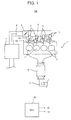
- FIG. 1 shows the fuel injection system 100 to which the control device for an internal combustion engine according to the present invention is applied.
- the solid arrows show examples of flows of gas in the figure.
- the fuel injection system 100 mainly includes an engine 1, first fuel injection valves 2, second fuel injection valves 3, a surge tank 4, a throttle valve 5, an intake passage 6, an air cleaner 7, an exhaust passage 8, and a catalyst 10.
- the engine 1 includes four cylinders 11, and each of the cylinders 11 is connected to the common surge tank 4 via an intake manifold.
- a first fuel injection valve 2 for injecting gas fuel On each of the cylinders 11, there are provided a first fuel injection valve 2 for injecting gas fuel and a second fuel injection valve 3 for injecting liquid fuel, respectively.
- the gas fuel may be CNG (Compressed Natural Gas), LPG (Liquefied Petroleum Gas) or LNG (Liquefied Natural Gas), for example.
- the liquid fuel may be gasoline, light oil, alcohol such as methanol and ethanol, and mixed fuel of them, for example.
- the surge tank 4 is connected to the air cleaner 7 via the intake passage 6, and the throttle valve 5 is arranged in the intake passage 6.
- the opening degree (hereinafter referred to as "throttle opening degree Thr") of the above-mentioned throttle valve 5 is controlled by the control signal supplied from the ECU 50.
- Each of the cylinders 11 is connected to the exhaust passage 8 via the common exhaust manifold.
- the catalyst 10 which is a three-way catalyst.
- the ECU 50 includes a CPU (Central Processing Unit), a ROM (Read Only Memory) and a RAM (Random Access Memory) which are not shown, and executes various control of each component in the fuel injection system 100. For example, the ECU 50 executes the control over the first fuel injection valves 2 and the second fuel injection valves 3 on the basis of the detection signals supplied from various sensors. The ECU 50 also executes the control of lowering the temperature (hereinafter referred to as "catalyst temperature Tb") of the catalyst 10 when it determines that the temperature of the catalyst 10 is high in case of a predetermined operating state.
- the ECU 50 functions as a control unit in the present invention.
- the ECU 50 lowers the catalyst temperature Tb and suppresses the deterioration of the catalyst 10.
- gas fuel operation herein indicates an operation in which the fuel injection by the first fuel injection valve 2 is executed, i.e., an operation in which the gas fuel is used
- liquid fuel operation herein indicates an operation in which the fuel injection by the second fuel injection valve 3 is executed, i.e. , an operation in which the liquid fuel is used.
- fuel cut herein indicates stopping the fuel injection with respect to a part of or all the cylinders 11.
- return from the fuel cut herein indicates restarting the fuel injection from a state of the fuel cut.
- the ECU 50 executes increase of the fuel injection quantity (hereinafter referred to as "fuel increasing") and switches to the gas fuel operation, when the catalyst temperature Tb becomes higher than a predetermined upper limit temperature at an operating range where the liquid fuel operation is executed.
- fuel increasing the fuel injection quantity
- the ECU 50 suppresses the deterioration of the catalyst 10 and lowers the catalyst temperature Tb.
- the ECU 50 determines whether or not the catalyst temperature Tb is higher than a predetermined upper limit temperature (hereinafter referred to as "upper limit temperature Tbth") while it executes the liquid fuel operation.
- the upper limit temperature Tbth is set by experimental trials to an upper limit value of the catalyst temperature Tb at which the deterioration of the catalyst 10 is not likely to occur, for example.
- the ECU 50 estimates the catalyst temperature Tb based on the load of the engine 1 and the rotational speed of the engine 1, for example. Then, the ECU 50 determines that the catalyst temperature Tb is higher than the upper limit temperature Tbth when the engine 1 is at a predetermined operating range where the load and the rotational speed are high. In another example, the ECU 50 measures the exhaust gas temperature based on a temperature sensor provided on the exhaust passage 8 which is not shown. Then, the ECU 50 estimates the catalyst temperature Tb from the above-mentioned exhaust gas temperature, and compares it to the upper limit temperature Tbth. In still another example, the ECU 50 detects the catalyst temperature Tb based on a temperature sensor not shown and provided on the catalyst 10, and compares it to the upper limit temperature Tbth.
- the ECU 50 executes the fuel increasing to make the air fuel ratio rich, and switches from the liquid fuel operation to the gas fuel operation.
- the ECU 50 can suppress the rise of the catalyst temperature Tb and the deterioration of the catalyst 10 due to the adhesion of the fuel to the intake port and/or the insides of the cylinders 11 at the time of the fuel cut.
- the ECU 50 can effectively lower the catalyst temperature Tb by switching from the liquid fuel operation to the gas fuel operation at the time of the fuel increasing.
- the ECU 50 can lower the packing efficiency and the intake air amount thereby to lower the exhaust gas temperature.
- the emission of the gas fuel is lower than the emission of the liquid fuel. Therefore, the ECU 50 can realize the low emission as a third effect of the first control by executing the gas fuel operation at the time of the fuel increasing.
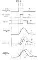
- FIG. 2 is an example of a time chart for explaining the behavior of the catalyst temperature Tb at the times of the liquid fuel operation and the gas fuel operation.
- FIG. 2 from the top shows the throttle opening degree Thr, "fuel-increasing amount” which indicates the increasing amount of the fuel injection due to the rise of the upper limit temperature Tb, the presence/absence of the fuel cut, "engine speed Ne” which indicates the rotational speed of the engine 1, "unburned fuel” which indicates the quantity of the unburned fuel remaining in the intake port and/or the cylinders, and the catalyst temperature Tb.
- Thr throttle opening degree Thr
- fuel-increasing amount which indicates the increasing amount of the fuel injection due to the rise of the upper limit temperature Tb
- engine speed Ne which indicates the rotational speed of the engine 1
- unburned fuel which indicates the quantity of the unburned fuel remaining in the intake port and/or the cylinders
- each of the graphs “B1" to “B4" shows the time variation of each component in common between the liquid fuel operation and the gas fuel operation.
- the graph “B5" shows the time variation of unburned fuel at the liquid fuel operation.
- the graph “B6” shows the time variation of unburned fuel at the gas fuel operation.
- the graph “B7” shows the time variation of the Tb at the liquid fuel operation, and the graph “B8” shows the time variation of the Tb at the gas fuel operation.
- the ECU 50 raises the fuel increasing in response to the rise of the catalyst temperature Tb (see the graph B2). Thereby, the ECU 50 increases the latent heat of vaporization of the fuel to lower the exhaust gas temperature.
- the unburned fuel increases in response to the fuel increasing (see graphs B5 and B6).
- the unburned fuel at the liquid fuel operation becomes larger than the unburned fuel at the gas fuel operation. Namely, the unburned fuel at the gas fuel operation is smaller than the unburned fuel at the liquid fuel operation because the gas fuel never adheres to the intake port or the inside of the combustion chamber.
- the throttle opening degree Thr descends (see graph B1).
- the ECU 50 executes the decelerating operation to start the fuel cut (see graph B3).
- the unburned fuel is discharged in large amounts at the time of the fuel cut, thereby to prompt the oxidation reaction of the catalyst 10.
- the catalyst 10 is under the condition of high temperature and oxidant atmosphere (see the graph B7). As a result, sintering of the noble metals in the catalyst 10 occurs, and the performance could deteriorate.
- the ECU 50 executes the liquid fuel operation at the time of the high temperature of the catalyst and the fuel increasing, a large amount of the unburned fuel remains in the engine 1. As a result, there is a possibility that the rise of the catalyst temperature Tb and the deterioration of the catalyst 10 are prompted.
- the ECU 50 increases the fuel injection quantity to make the air fuel ratio rich, and switches from the liquid fuel operation to the gas fuel operation. Thereby, the ECU 50 can suppress the adhesion of the fuel to the intake port and/or the insides of the cylinders 11 and also suppress the deterioration of the catalyst 10 while lowering the catalyst temperature Tb.
- the ECU 50 sets the timing of re-switching to the liquid fuel operation to the timing of the return from the fuel cut.
- the ECU 50 executes the fuel increasing and switches to the gas fuel operation on the basis of the first control. After that, the ECU 50 continues the gas fuel operation until the return from the fuel cut. Then, the ECU 50 starts the fuel cut at the time of the deceleration, and at the time of the return thereof, it switches from the gas fuel operation to the liquid fuel operation. Thereby, at the time of switching the fuel, the ECU 50 can eliminate the influence due to the previously-used fuel remaining, by scavenging the inside of the combustion chamber by using air.
- the ECU 50 initially injects the liquid fuel to the cylinder 11 which executes the combustion stroke following the last cylinder 11 combusted by the gas fuel.
- the ECU 50 equally scavenges each of the cylinders 11 by air, and it can certainly eliminate the influence of the previously-used fuel remaining.
- the ECU 50 executes the fuel increasing and switches to the gas fuel operation, if the catalyst temperature Tb at the liquid fuel operation is higher than the upper limit temperature Tbth at the time of acceleration and/or shifting gears of the transmission when the ignition timing is retarded. Thereby, the ECU 50 lowers the catalyst temperature Tb while it realizes the low emission.
- FIG. 3 is one example of the time chart showing the schematic processing in the third control at the time when the vehicle is accelerating. From the top, FIG. 3 shows the catalyst temperature Tb, ignition timing, fuel-increasing amount at the time when the catalyst temperature is high, the presence/absence of the gas fuel operation, the presence/absence of the gas fuel operation, and the presence/absence of the liquid fuel operation. It is assumed that the ECU 50 executes the liquid fuel operation at the start of the time chart.
- the ECU 50 retards the ignition timing for a constant time in response to shifting gears of the transmission (see graph C2). In this case, however, the ECU 50 determines that the catalyst temperature Tb does not need to be lowered because the catalyst temperature Tb is equal to or lower than the upper limit temperature Tbth, and it does not execute the fuel increasing (see graph C3).
- the catalyst temperature Tb exceeds the upper limit temperature Tbth due to the rise of the exhaust gas temperature of the engine 1 (see the graph C1).
- the ECU 50 makes the ignition timing retarded again in response to shifting gears of the transmission (see the graph C2).
- the ECU 50 executes the fuel increasing in addition to retarding the ignition timing (see the graph C3), and switches from the liquid fuel operation to the gas fuel operation (see the graphs C4 and C5).
- the ECU 50 can lower the packing efficiency and the intake air amount to lower the exhaust gas temperature effectively.
- the ECU 50 stops the fuel increasing and switches from the gas fuel operation to the liquid fuel operation (see the graphs C3 to C5). In this way, by executing the gas fuel operation in case of the operating range where the air fuel ratio becomes rich by the fuel increasing, the ECU 50 can realize the low emission.
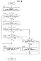
- FIG. 4 is an example of a flow chart showing the procedure of the process in which the first control and the second control are executed at the same time.
- the flow chart shown in FIG. 4 is repeatedly executed by the ECU 50 in a predetermined cycle.
- the ECU 50 detects the operating state of the engine 1 (step S101). Concretely, the ECU 50 detects which one of the liquid fuel or the gas fuel is currently used, whether or not the fuel cut is being executed, and whether or not the fuel increasing in response to the rise of the catalyst temperature Tb is being executed.
- the ECU 50 determines whether or not the operating range is the operating range of the liquid fuel operation (step S102). For example, the ECU 50 determines whether or not the operating range is the operating range of the liquid fuel operation on the basis of the current operating state with reference to a map prepared in advance. When the ECU 50 determines that the operating range is the operating range of the liquid fuel operation (step S102; Yes), the process goes to step S103. In contrast, when the ECU 50 determines that the operating range is not the operating range of the liquid fuel operation (step S102; No), i.e. , determines that the gas fuel operation should be executed, it executes the gas fuel operation (step S106). At that moment, the ECU 50 may execute the fuel increasing when the condition for executing the fuel increasing is met.
- the ECU 50 detects the catalyst temperature Tb (step S103).
- the ECU 50 may estimate the catalyst temperature Tb based on the load and the rotational speed of the engine 1, or may detect the catalyst temperature Tb based on the detection value of the temperature sensor provided on the catalyst 10.
- the ECU 50 determines whether or not the catalyst temperature Tb is higher than the upper limit temperature Tbth (step S104).
- the upper limit temperature Tbth is set, by experimental trials in advance, to an upper limit of the upper limit temperature Tb at which the deterioration of the catalyst 10 is not likely to occur.
- the ECU 50 determines that the catalyst temperature Tb is higher than the upper limit temperature Tbth (step S104; Yes)
- the process goes to step S105.
- the ECU 50 determines that the catalyst temperature Tb is equal to or lower than the upper limit temperature Tbth (step S104; No) it determines that it does not have to execute the fuel increasing and switch to the gas fuel operation in order to lower the catalyst temperature Tb, and the process goes to step S107.
- step S105 the ECU 50 determines whether or not condition of the fuel increasing is met. Concretely, if there are some conditions for executing the fuel increasing other than the upper limit temperature Tb, the ECU 50 determines whether or not these conditions are met.
- step S105 determines that the condition of the fuel increasing is met (step S105; Yes)
- step S106 executes the fuel increasing by the gas fuel operation.
- the ECU 50 prevents the unburned fuel from remaining in the intake port or in the cylinder due to the fuel increasing thereby to suppress the deterioration of the catalyst 10 and the rise of the catalyst temperature Tb at the time of the fuel cut, and it also lowers the packing efficiency and the intake air amount thereby to lower the exhaust gas temperature and the catalyst temperature Tb.
- step S105 determines that the condition of the fuel increasing is not met (step S105; No)
- the process goes to step S107.
- step S107 When the catalyst temperature Tb is equal to or lower than the upper limit temperature Tbth (step S104; No), or when the condition of the fuel increasing is not met (step S105; No), the ECU 50 determines whether or not the fuel cut is being executed (step S107). When the fuel cut is being executed (step S107; Yes), the ECU 50 executes the liquid fuel operation (step S108). For example, after the ECU 50 switches from the liquid fuel operation to the gas fuel operation at step S106, it executes the flow chart again.
- the ECU 50 executes the liquid fuel operation after the execution of the fuel cut if the operating range is the operating range of the liquid fuel operation (step S102; Yes) and the catalyst temperature Tb is equal to or lower than the upper limit temperature Tbth (step S104; Yes).
- the ECU 50 can scavenge the combustion chamber in each of the cylinders 11, and can eliminate the influence caused by the previously-used fuel remaining in the cylinders.
- step S107 when the ECU 50 determines that the fuel cut is not being executed (step S107; No), the process end.
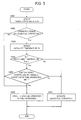
- FIG. 5 is one example of a flowchart showing a procedure of the process according to the third control.
- the ECU 50 repeatedly executes the process shown in FIG. 5 in a predetermined cycle, for example.
- the ECU 50 detects the operating state of the engine 1 (step S201).
- the ECU 50 determines whether or not the operating range is the operating range of the liquid fuel operation (step S202).
- the ECU 50 determines that the operating range is the operating range of the liquid fuel operation (step S202; Yes)
- the process goes to step S203.
- the ECU 50 determines that the operating range is not the operating range of the liquid fuel operation (step S202; No)
- the ECU 50 determines that the operating range is not the operating range of the liquid fuel operation (step S202; No)
- the ECU 50 may execute the fuel increasing when the condition for executing the fuel increasing is met.
- the ECU 50 detects the catalyst temperature Tb (step S203). Then, the ECU 50 determines whether or not the catalyst temperature Tb is higher than the upper limit temperature Tbth (step S204). When the ECU 50 determines that the catalyst temperature Tb is higher than the upper limit temperature Tbth (step S204; Yes), the process goes to step S205. In contrast, when the ECU 50 determines that the catalyst temperature Tb is equal to or lower than the upper limit temperature Tbth (step S204; No), it executes the liquid fuel operation (step S207). In this case, the ECU 50 does not execute the fuel increasing due to the rise of the catalyst temperature Tb.
- the ECU 50 determines whether or not the ignition timing is controlled to be retarded and the condition of the fuel increasing is met (step S205). Concretely, the ECU 50 determines whether or not the ignition timing is retarded for the reason that acceleration or shifting gears of the transmission is being executed, and whether or not the condition of the fuel increasing is,met.
- the ECU 50 determines that the ignition timing is controlled to be retarded and the condition of the fuel increasing is met (step S205; Yes)
- the ECU 50 executes the fuel increasing while retarding the ignition timing and also switches from the liquid fuel operation to the gas fuel operation. Thereby, the ECU 50 realizes the low emission while executing the fuel increasing, and lowers the intake air amount and the packing efficiency thereby to lower the exhaust gas temperature.
- step S205 determines that the ignition timing is not controlled to be retarded or the condition of the fuel increasing is not met (step S205; No). It executes the liquid fuel operation (step S207).
- the ECU 50 switches from the liquid fuel operation to the gas fuel operation when the catalyst temperature Tb is higher than the upper limit temperature Tbth and the predetermined condition is met.
- the method to which the present invention is applied is not limited to this method.
- the ECU 50 may increase the use proportion of the gas fuel to the fuel used for the combustion of the engine 1 when the catalyst temperature Tb is higher than the upper limit temperature Tbth and the predetermined condition is met. Namely, in this case, the ECU 50 may increase the proportion of the gas-fuel use while continuing to use the liquid fuel. Thereby, while suppressing the increase of the unburned fuel at the time of the fuel increasing, the ECU 50 can lower the packing efficiency and the intake air amount thereby to lower the exhaust gas temperature, similarly to the above-mentioned embodiment.
- step S105 when the condition of the fuel increasing is met (step S105; Yes), the ECU 50 executes the fuel increasing and increases the proportion of the gas fuel to the fuel used for combustion of the engine 1. Besides, after the execution of the step S106, the ECU 50 re-executes the process of the flowchart, and returns the proportion of the gas-fuel use to its original value when it determines that the fuel cut is being executed (step S107; Yes).
- step S205 when the ignition timing is controlled to be retarded and the condition of the fuel increasing is met (step S205; Yes), the ECU 50 executes the fuel increasing and increases the use proportion of the gas fuel to the fuel used for the combustion of the engine 1.
Landscapes
- Engineering & Computer Science (AREA)
- Chemical & Material Sciences (AREA)
- Combustion & Propulsion (AREA)
- Mechanical Engineering (AREA)
- General Engineering & Computer Science (AREA)
- Oil, Petroleum & Natural Gas (AREA)
- Electrical Control Of Air Or Fuel Supplied To Internal-Combustion Engine (AREA)
- Output Control And Ontrol Of Special Type Engine (AREA)
- Exhaust Gas After Treatment (AREA)
- Combined Controls Of Internal Combustion Engines (AREA)
Applications Claiming Priority (1)
| Application Number | Priority Date | Filing Date | Title |
|---|---|---|---|
| PCT/JP2010/054233 WO2011111224A1 (ja) | 2010-03-12 | 2010-03-12 | 内燃機関の制御装置 |
Publications (2)
| Publication Number | Publication Date |
|---|---|
| EP2546490A1 true EP2546490A1 (de) | 2013-01-16 |
| EP2546490A4 EP2546490A4 (de) | 2017-06-07 |
Family
ID=44563066
Family Applications (1)
| Application Number | Title | Priority Date | Filing Date |
|---|---|---|---|
| EP10847454.5A Withdrawn EP2546490A4 (de) | 2010-03-12 | 2010-03-12 | Steuerungsvorrichtung für einen verbrennungsmotor |
Country Status (5)
| Country | Link |
|---|---|
| US (1) | US9057331B2 (de) |
| EP (1) | EP2546490A4 (de) |
| JP (1) | JP5348313B2 (de) |
| CN (1) | CN102482974B (de) |
| WO (1) | WO2011111224A1 (de) |
Cited By (1)
| Publication number | Priority date | Publication date | Assignee | Title |
|---|---|---|---|---|
| GB2499093A (en) * | 2012-02-02 | 2013-08-07 | Ford Global Tech Llc | Method for influencing thermal balance of an internal combustion engine and an associated engine |
Families Citing this family (7)
| Publication number | Priority date | Publication date | Assignee | Title |
|---|---|---|---|---|
| US9239018B2 (en) * | 2010-06-16 | 2016-01-19 | Toyota Jidosha Kabushiki Kaisha | Fuel control apparatus for internal combustion engine |
| US20160222895A1 (en) * | 2011-12-16 | 2016-08-04 | General Electric Company | Multi-fuel system and method |
| JP2014134128A (ja) * | 2013-01-09 | 2014-07-24 | Denso Corp | 内燃機関の燃料噴射制御装置 |
| US9932877B2 (en) * | 2013-05-10 | 2018-04-03 | Ford Global Technologies, Llc | Integrated fuel catalyst monitor |
| DE102015204544A1 (de) * | 2015-03-13 | 2016-09-15 | Robert Bosch Gmbh | Verfahren zum Betreiben einer zumindest zeitweise mit Gas betriebenen Brennkraftmaschine |
| US11835016B2 (en) | 2021-09-01 | 2023-12-05 | American CNG, LLC | Supplemental fuel system for compression-ignition engine |
| US20260015980A1 (en) * | 2024-07-09 | 2026-01-15 | Caterpillar Inc. | Systems and methods for controlling cylinder combustion in a dual fuel engine using in-cylinder pressure sensing |
Family Cites Families (17)
| Publication number | Priority date | Publication date | Assignee | Title |
|---|---|---|---|---|
| GB8425577D0 (en) * | 1984-10-10 | 1984-11-14 | Flintheath Ltd | Fuel control system |
| JPH06221193A (ja) | 1993-01-29 | 1994-08-09 | Mazda Motor Corp | 気体燃料供給エンジン |
| CN1093595C (zh) * | 2000-12-28 | 2002-10-30 | 上海交通大学 | 双燃料汽车双达标低排放控制系统 |
| JP4439760B2 (ja) | 2001-05-10 | 2010-03-24 | 本田技研工業株式会社 | 内燃機関の燃料供給制御装置 |
| JP2003065027A (ja) * | 2001-08-29 | 2003-03-05 | Suzuki Motor Corp | 内燃機関の排気温度センサ制御装置 |
| US6742335B2 (en) * | 2002-07-11 | 2004-06-01 | Clean Air Power, Inc. | EGR control system and method for an internal combustion engine |
| CA2422188A1 (en) * | 2002-10-02 | 2004-04-02 | Westport Research Inc. | Bypass controlled regeneration of nox adsorbers |
| US6865881B2 (en) * | 2002-11-18 | 2005-03-15 | Diesel & Combustion Technologies, Llc | System and method for reducing nitrogen oxides in combustion exhaust streams |
| JP4552590B2 (ja) | 2004-10-14 | 2010-09-29 | トヨタ自動車株式会社 | 内燃機関の制御装置 |
| DE102005004880B4 (de) * | 2005-02-03 | 2015-05-28 | Robert Bosch Gmbh | Verfahren und Vorrichtung zur Abgastemperaturregelung |
| US7877996B2 (en) * | 2005-11-28 | 2011-02-01 | Ford Global Technologies, Llc | Turbo-lag compensation system having an ejector |
| JP2008002431A (ja) | 2006-06-26 | 2008-01-10 | Yamaha Motor Co Ltd | 内燃機関 |
| JP2008133726A (ja) | 2006-11-27 | 2008-06-12 | Toyota Motor Corp | アルコール燃料内燃機関 |
| JP4765941B2 (ja) * | 2007-01-09 | 2011-09-07 | トヨタ自動車株式会社 | 内燃機関の制御装置及び方法 |
| US8161732B2 (en) * | 2008-03-05 | 2012-04-24 | Ford Global Technologies, Llc | System and method to improve engine emissions for a dual fuel engine |
| JP4985530B2 (ja) | 2008-04-18 | 2012-07-25 | トヨタ自動車株式会社 | 内燃機関の制御装置 |
| US8341949B2 (en) * | 2008-05-30 | 2013-01-01 | Caterpillar Inc. | After-treatment system |
-
2010
- 2010-03-12 CN CN201080037371.7A patent/CN102482974B/zh not_active Expired - Fee Related
- 2010-03-12 US US13/498,494 patent/US9057331B2/en not_active Expired - Fee Related
- 2010-03-12 WO PCT/JP2010/054233 patent/WO2011111224A1/ja not_active Ceased
- 2010-03-12 JP JP2012504249A patent/JP5348313B2/ja not_active Expired - Fee Related
- 2010-03-12 EP EP10847454.5A patent/EP2546490A4/de not_active Withdrawn
Non-Patent Citations (1)
| Title |
|---|
| See references of WO2011111224A1 * |
Cited By (3)
| Publication number | Priority date | Publication date | Assignee | Title |
|---|---|---|---|---|
| GB2499093A (en) * | 2012-02-02 | 2013-08-07 | Ford Global Tech Llc | Method for influencing thermal balance of an internal combustion engine and an associated engine |
| US9328675B2 (en) | 2012-02-02 | 2016-05-03 | Ford Global Technologies, Llc | Method for influencing the thermal balance of an internal combustion engine |
| GB2499093B (en) * | 2012-02-02 | 2018-12-05 | Ford Global Tech Llc | Method for influencing the thermal balance of an internal combustion engine and an internal combustion engine for implementing such a method |
Also Published As
| Publication number | Publication date |
|---|---|
| US20120324870A1 (en) | 2012-12-27 |
| JP5348313B2 (ja) | 2013-11-20 |
| JPWO2011111224A1 (ja) | 2013-06-27 |
| US9057331B2 (en) | 2015-06-16 |
| CN102482974B (zh) | 2014-05-07 |
| WO2011111224A1 (ja) | 2011-09-15 |
| CN102482974A (zh) | 2012-05-30 |
| EP2546490A4 (de) | 2017-06-07 |
Similar Documents
| Publication | Publication Date | Title |
|---|---|---|
| US9057331B2 (en) | Control device for internal combustion engine | |
| US8100107B2 (en) | Method and system for engine control | |
| US8141533B2 (en) | Control apparatus and method for internal combustion engine | |
| US8347852B2 (en) | Method and system for pre-ignition control | |
| US7962275B2 (en) | Control device and control method for internal combustion engine | |
| US9429057B2 (en) | Method and an apparatus for warming a catalyst in an internal combustion engine | |
| EP2775127B1 (de) | Steuerungsvorrichtung für einen verbrennungsmotor | |
| US20130035841A1 (en) | Method and system for pre-ignition control | |
| US8695575B2 (en) | Control device for internal combustion engine | |
| EP2527621A1 (de) | Steuerungsvorrichtung für einen verbrennungsmotor | |
| EP2700803A1 (de) | Steuervorrichtung und verfahren für einen verbrennungsmotor | |
| CN100567775C (zh) | 用于内燃机的控制装置 | |
| EP2108801A1 (de) | Elektronische Steuereinheit zur automatischen Schaltung zwischen zwei Kraftstoffsystemen basierend auf den Motorbedingungen | |
| CN103080508B (zh) | 内燃机的控制装置及方法 | |
| JP2010101197A (ja) | 内燃機関の点火時期制御システム | |
| EP2634399A1 (de) | Kraftstoffeinspritzsystem für einen verbrennungsmotor | |
| JP2010265815A (ja) | 内燃機関の燃料噴射システム | |
| JP2006132399A (ja) | 過給機付エンジンの制御装置および制御方法 | |
| JP2008157141A (ja) | アルコールを主成分とする燃料を使用した内燃機関 | |
| JP2005240568A (ja) | 内燃機関の燃料噴射制御装置 | |
| WO2012168793A1 (en) | Control unit and control method for internal combustion engine |
Legal Events
| Date | Code | Title | Description |
|---|---|---|---|
| PUAI | Public reference made under article 153(3) epc to a published international application that has entered the european phase |
Free format text: ORIGINAL CODE: 0009012 |
|
| 17P | Request for examination filed |
Effective date: 20120224 |
|
| AK | Designated contracting states |
Kind code of ref document: A1 Designated state(s): AT BE BG CH CY CZ DE DK EE ES FI FR GB GR HR HU IE IS IT LI LT LU LV MC MK MT NL NO PL PT RO SE SI SK SM TR |
|
| RAP1 | Party data changed (applicant data changed or rights of an application transferred) |
Owner name: TOYOTA JIDOSHA KABUSHIKI KAISHA |
|
| DAX | Request for extension of the european patent (deleted) | ||
| RA4 | Supplementary search report drawn up and despatched (corrected) |
Effective date: 20170509 |
|
| RIC1 | Information provided on ipc code assigned before grant |
Ipc: F01N 3/24 20060101AFI20170502BHEP Ipc: F02D 41/02 20060101ALI20170502BHEP Ipc: F02D 19/06 20060101ALI20170502BHEP |
|
| STAA | Information on the status of an ep patent application or granted ep patent |
Free format text: STATUS: THE APPLICATION HAS BEEN WITHDRAWN |
|
| 18W | Application withdrawn |
Effective date: 20170622 |