EP2546560A1 - Procédé de pose d'un pipeline et réservoir de récupération pour son utilisation - Google Patents
Procédé de pose d'un pipeline et réservoir de récupération pour son utilisation Download PDFInfo
- Publication number
- EP2546560A1 EP2546560A1 EP12175577A EP12175577A EP2546560A1 EP 2546560 A1 EP2546560 A1 EP 2546560A1 EP 12175577 A EP12175577 A EP 12175577A EP 12175577 A EP12175577 A EP 12175577A EP 2546560 A1 EP2546560 A1 EP 2546560A1
- Authority
- EP
- European Patent Office
- Prior art keywords
- recovery tank
- pipes
- route
- pipeline
- transport
- Prior art date
- Legal status (The legal status is an assumption and is not a legal conclusion. Google has not performed a legal analysis and makes no representation as to the accuracy of the status listed.)
- Withdrawn
Links
- 238000011084 recovery Methods 0.000 title claims abstract description 82
- 238000000034 method Methods 0.000 title claims abstract description 17
- 239000003381 stabilizer Substances 0.000 claims description 9
- 238000007796 conventional method Methods 0.000 description 2
- 239000004576 sand Substances 0.000 description 2
- 229910000831 Steel Inorganic materials 0.000 description 1
- 238000004873 anchoring Methods 0.000 description 1
- 230000003466 anti-cipated effect Effects 0.000 description 1
- 238000010276 construction Methods 0.000 description 1
- 238000006073 displacement reaction Methods 0.000 description 1
- 239000007789 gas Substances 0.000 description 1
- 239000007788 liquid Substances 0.000 description 1
- 238000005096 rolling process Methods 0.000 description 1
- 239000010959 steel Substances 0.000 description 1
- 239000000725 suspension Substances 0.000 description 1
Images

Classifications
-
- F—MECHANICAL ENGINEERING; LIGHTING; HEATING; WEAPONS; BLASTING
- F16—ENGINEERING ELEMENTS AND UNITS; GENERAL MEASURES FOR PRODUCING AND MAINTAINING EFFECTIVE FUNCTIONING OF MACHINES OR INSTALLATIONS; THERMAL INSULATION IN GENERAL
- F16L—PIPES; JOINTS OR FITTINGS FOR PIPES; SUPPORTS FOR PIPES, CABLES OR PROTECTIVE TUBING; MEANS FOR THERMAL INSULATION IN GENERAL
- F16L1/00—Laying or reclaiming pipes; Repairing or joining pipes on or under water
- F16L1/024—Laying or reclaiming pipes on land, e.g. above the ground
- F16L1/028—Laying or reclaiming pipes on land, e.g. above the ground in the ground
- F16L1/036—Laying or reclaiming pipes on land, e.g. above the ground in the ground the pipes being composed of sections of short length
Definitions
- the invention relates to a method for laying a pipeline, comprising the steps of:
- Such a method is generally known and is applied in the laying of pipelines, for instance for transport of gases or liquids over great distances.
- This transporter is a converted bulldozer with a number of frameworks on either side for the purpose of carrying the pipes.
- the mobile crane can be formed by an excavator having a special tool for picking up the pipes at the end of its excavator arm. Once the transporter has been loaded, it travels through the terrain to the location alongside the trench where the pipes will be used. The transporter is there unloaded by a second mobile crane.
- the pipes have in practice a length between 15 and 20 metres at a diameter of 1 metre 20 (48 inches).
- the weight of such pipes can amount to almost 15 tons. This entails that a truck can supply only two or three such pipes, while the special pipe transporter will be able, depending on the ground conditions, to transport four to six pipes, so two truckloads. Using the known method it is possible to lay about 500 metres of pipeline in a 10-hour working day.
- the known method has a number of drawbacks. Firstly, it requires considerable investment since, in addition to the special pipe transporter, two mobile cranes are necessary, one for unloading the trucks at the transfer location and one for unloading the pipe transporter at the trench.
- the use of a pipe transporter based on a bulldozer undercarriage moreover has the drawback that the terrain is heavily loaded as a result. This is the result of the rigid construction and the short length of the running gear of a bulldozer.
- This pipe transporter can moreover not travel on the road because the steel running gear would damage the road surface. This means that, when a pipeline intersects a road, the pipe transporter has to be "ferried" across at this location using a low loader. This is laborious and time-consuming.
- the invention now has for its object to provide a method of the above described type wherein these drawbacks do not occur, or at least do so to lesser extent. According to the invention this is achieved in such a method in that the steps c), d) and e) are performed by a recovery tank.
- a recovery tank which can take the pipes from the truck, transport them overland and set them down again on site, it is possible to suffice with considerably less equipment than in the conventional method.
- the recovery tank fulfills the function of both pipe transporter and mobile crane.
- a tank is also considerably faster and more manoeuvrable. Because the running gear of a tank moreover comprises rubber blocks, a recovery tank does not damage the road surface, or hardly so.
- a recovery tank can in any case cross a road which the pipeline may intersect.
- a recovery tank has a sufficient own weight to remain stable when a considerable distance has to be spanned during loading or unloading of the pipes.
- step c) the recovery tank preferably lifts the pipes off the truck and places them on a transport framework. The truck can thus be unloaded quickly.
- the pipes are preferably placed here in step c) on a transport framework arranged on the recovery tank.
- the recovery tank itself then functions as pipe transporter.
- the pipes being placed on a transport framework arranged on a trailer pulled by the recovery tank.
- the recovery tank thus (also) functions as tractive vehicle for a non-self-propelling pipe transporter.
- the recovery tank itself can in this case also be loaded, whereby more pipes can be transported in one run.
- a telescopic crane arranged on the recovery tank.
- Such a telescopic crane has a relatively wide reach, certainly compared to the arm of an excavator, whereby pipes can be picked up from further away and can also be set down over a greater distance without displacements of the recovery tank itself being necessary for this purpose.
- the invention further relates to a recovery tank which can be used in a method as described above.
- this recovery tank is provided with at least one transport framework for pipes.
- the transport framework is preferably adapted to carry the pipes in the direction of travel.
- the pipes which are relatively long, can hereby be properly supported and transported in stable manner.
- the recovery tank is preferably provided with two transport frameworks arranged on either side of the tank. These frameworks can be movable between a retracted transport position and an extended position of use. This movement can be driven hydraulically.
- the recovery tank is more preferably provided with a telescopic crane.
- the crane is mounted rotatably thereon. Pipes can thus be picked up and set down at different positions relative to the recovery tank.
- the telescopic crane preferably has a capacity of at least 40 tons-metre, more preferably at least 70 tons-metre and most preferably at least 100 tons-metre. Relatively large and heavy pipes can thus be displaced over a relatively wide range.
- stabilizer jacks In order to increase the stability of the recovery tank during use of the telescopic crane, it is preferably provided with stabilizer jacks. These stabilizer jacks can be movable, for instance hydraulically, between a retracted transport position and an extended position of use.
- the recovery tank is preferably further provided with means for pulling a trailer. As stated, this can increase the transport capacity.
- a route 2 for the pipeline is first determined, after which pipes 3 are supplied which are connected to each other adjacently of route 2 to form a pipeline. Then excavated at the position of the marked route 2 is a trench in which pipeline 1 is placed.
- Pipes 3 are produced in a factory and supplied by road 5 on a truck 4. Because pipelines are generally laid some distance from other infrastructure and trucks are usually unsuitable for off-road travel, pipes 3 have to be transported from road 5 to route 2 by an all-terrain vehicle specially suited for the purpose. Truck 4 is for this purpose unloaded at a transfer location 6, and pipes 3 are transferred here to the all-terrain vehicle.
- a recovery tank 8 as all-terrain vehicle for transporting pipes 3 over terrain 7 between transfer location 6 and route 2.
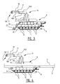
- This recovery tank is provided with a running gear 9 with two caterpillars 10 running over wheels 11. These wheels 11 are independently suspended and caterpillars 10 are relatively long so that the surface pressure is relatively low, and so the terrain is not damaged too badly when recovery tank 8 passes.
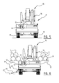
- Recovery tank 8 is further provided on either side of its chassis 13 with transport frameworks 12 on which pipes 3 can be transported. These transport frameworks 12 can be folded in and out hydraulically so that the width of recovery tank 8 remains limited when it is not transporting pipes. Transport frameworks 12 are provided with recesses 23, the dimensions of which are adjusted to the diameter of pipes 3 to be transported. For use in uneven terrain extra recesses can optionally also be provided with which pipes 3 can be clamped in order to prevent them sliding or rolling off.
- Recovery tank 8 is further provided with a telescopic crane 14, the base 15 of which is mounted for rotation about a vertical axis V in chassis 13.
- Arm 16 of crane 14 is mounted in base 15 for pivoting about a horizontal axis H.
- Arm 16 has a first segment 16A and a second segment 16B pivotally connected thereto.
- Segment 16B forms the basis of the telescopic part, which comprises three extendable segments 16C-E which can be extended and retracted relative to each other by means of hydraulic jacks 17, 18.
- the pivoting movement of second segment 16B relative to first segment 16A takes place by means of a hydraulic jack 19, while the pivoting movement of arm 16 relative to base 15 is effected by a hydraulic jack 20.
- the capacity of telescopic crane 14 and the size, the performance and the weight of recovery tank 8 are adapted to the anticipated loads.
- Pipes 3 will in practice have a weight of a maximum of 15 tons.
- a crane 14 is required with a capacity of at least 100 tons-metre.
- a recovery tank 8 with a smaller crane 14, for instance a crane of 40 or 50 tons-metre.
- the own weight of recovery tank 8 and the track width of its running gear 9 must be large enough to also be able to handle pipes 3 adjacently of recovery tank 8. Considering the length of pipes 3, they are after all placed in longitudinal direction of recovery tank 8, i.e. in the direction of travel, on transport frameworks 12 on the sides. In order to prevent recovery tank 8 tilting under this load an own weight is required in the order of 60 tons - including crane 14 - at a track width of 2.5 to 3 metres.
- telescopic crane 14 The dimensions and capacity of telescopic crane 14 are here also such that pipes 3 can be rotated in the air. This means that crane 14 must be able to bear the weight of a pipe 3 when arm 16 is extended telescopically over at least half the length of pipe 3.
- Front stabilizer jack 25 is formed here by a dozer blade which often already forms part of the standard equipment of recovery tank 8. This dozer blade 25 can be folded out by means of hydraulic jacks 26 until it lies flat on the ground and thus forms a stabilizer jack.
- Each side stabilizer jack 24 comprises a plank 27 extending roughly along the length of running gear 9. This plank 27 is attached with pivot arms 28 to the side of recovery tank 8 and can be folded in and out by hydraulic jacks 29.
- Recovery tank 8 is finally also provided with means 21 for attaching a trailer 22 thereto, for instance a caterpillar vehicle or other terrain vehicle without its own drive.
- These attaching means are for instance adapted to receive one end of a pull rod or pulling frame, the other end of which can be attached to trailer 22.
- Such attaching means 21 can be provided on both the rear side and front side of recovery tank 8.
- Figure 1A shows how recovery tank 8 unloads a truck 4 loaded with pipes 3 and sets down these pipes 3 on transport frameworks 12 along its own sides.
- some of the pipes 3 are loaded onto a trailer 22 which in the shown embodiment is coupled behind recovery tank 8.
- For the purpose of unloading truck 4 and loading recovery tank 8 and trailer 22 use is made of the extendability of crane 14 and the rotatability thereof about the different axes V, H.
- recovery tank 8 travels through terrain 7 to route 2.
- a service road or sand track can otherwise be constructed toward or along the route in order to improve accessibility.
- pipes 3 are there once again unloaded from recovery tank 8 and laid alongside route 2, as shown in figure 1B .
- pipes 3 are also unloaded therefrom and placed alongside route 2.
- Pipes 3 are here placed 'mitred' to some extent on sand heaps 30. Because recovery tank 8 is highly manoeuvrable and crane 14 moreover enables very many movements, pipes 3 can be laid accurately alongside the route so that they can then be connected to each other in simple manner.
- recovery tank 8 returns to transfer location 6 to pick up a new load of pipes.
- the thus supplied pipes 3 are then aligned and connected to each other to form a pipe string. Subsequently or simultaneously, a trench is dug along the marked route 2 in which the pipe string is finally placed.
- Recovery tank 8 which forms both a mobile crane and a transport vehicle it is thus possible to achieve a high productivity in the supply of pipes for laying a pipeline. Owing to its versatility the recovery tank can also be used for other operations.
- the relatively large and strong crane thus makes the tank suitable for all manner of hoisting operations, both stationary and mobile.
- Recovery tank 8 can thus also be used to transport and place concrete anchoring elements for the pipeline in the trench.
- Recovery tank 8 can also be utilized in pulling or hoisting the pipeline into a parabolic shape before it is placed in the trench ( fig. 1B ), and in the final lowering of the pipeline into the trench.
- the recovery tank is usually also equipped with a winch, whereby heavy winching operations as well as salvage operations are of course possible.
- the tank can further also be used to carry out earthworks, for instance cutting or deep-ploughing.
Landscapes
- Engineering & Computer Science (AREA)
- General Engineering & Computer Science (AREA)
- Mechanical Engineering (AREA)
- Loading And Unloading Of Fuel Tanks Or Ships (AREA)
- Sewage (AREA)
Applications Claiming Priority (1)
| Application Number | Priority Date | Filing Date | Title |
|---|---|---|---|
| NL2007075 | 2011-07-09 |
Publications (1)
| Publication Number | Publication Date |
|---|---|
| EP2546560A1 true EP2546560A1 (fr) | 2013-01-16 |
Family
ID=46581745
Family Applications (1)
| Application Number | Title | Priority Date | Filing Date |
|---|---|---|---|
| EP12175577A Withdrawn EP2546560A1 (fr) | 2011-07-09 | 2012-07-09 | Procédé de pose d'un pipeline et réservoir de récupération pour son utilisation |
Country Status (2)
| Country | Link |
|---|---|
| EP (1) | EP2546560A1 (fr) |
| NL (1) | NL2009158B1 (fr) |
Citations (6)
| Publication number | Priority date | Publication date | Assignee | Title |
|---|---|---|---|---|
| US3101530A (en) * | 1960-08-29 | 1963-08-27 | George A Coscia | Method of fabricating elongated underground conduits |
| EP0244124A1 (fr) * | 1986-05-02 | 1987-11-04 | Vickers Public Limited Company | Véhicule blindé avec grue |
| US20040190995A1 (en) * | 2003-03-24 | 2004-09-30 | Komatsu Ltd. | Pipelayer |
| EP1785689A1 (fr) * | 2005-11-14 | 2007-05-16 | NEXTER Systems | Véhicule de génie civil ou militaire |
| US20090097922A1 (en) * | 2007-10-10 | 2009-04-16 | Miller Beverly A | Apparatus, system, and method for concurrently laying multiple pipelines |
| US20090297275A1 (en) * | 2008-05-29 | 2009-12-03 | Volvo Construction Equipment Ab | Pipelayer With Cab Riser |
-
2012
- 2012-07-09 EP EP12175577A patent/EP2546560A1/fr not_active Withdrawn
- 2012-07-09 NL NL2009158A patent/NL2009158B1/nl not_active IP Right Cessation
Patent Citations (6)
| Publication number | Priority date | Publication date | Assignee | Title |
|---|---|---|---|---|
| US3101530A (en) * | 1960-08-29 | 1963-08-27 | George A Coscia | Method of fabricating elongated underground conduits |
| EP0244124A1 (fr) * | 1986-05-02 | 1987-11-04 | Vickers Public Limited Company | Véhicule blindé avec grue |
| US20040190995A1 (en) * | 2003-03-24 | 2004-09-30 | Komatsu Ltd. | Pipelayer |
| EP1785689A1 (fr) * | 2005-11-14 | 2007-05-16 | NEXTER Systems | Véhicule de génie civil ou militaire |
| US20090097922A1 (en) * | 2007-10-10 | 2009-04-16 | Miller Beverly A | Apparatus, system, and method for concurrently laying multiple pipelines |
| US20090297275A1 (en) * | 2008-05-29 | 2009-12-03 | Volvo Construction Equipment Ab | Pipelayer With Cab Riser |
Also Published As
| Publication number | Publication date |
|---|---|
| NL2009158A (nl) | 2013-01-14 |
| NL2009158B1 (nl) | 2016-07-15 |
Similar Documents
| Publication | Publication Date | Title |
|---|---|---|
| JP5940683B2 (ja) | キャリアシステム | |
| CN102596790B (zh) | 轻型高性能铺管机 | |
| US20100108632A1 (en) | Pipelayer Crane Excavator Apparatus and Methods | |
| EP3401447B1 (fr) | Machine mobile munie de chaîne de chenilles | |
| JP2015509472A5 (ja) | キャリアシステム | |
| CN101489907A (zh) | 铺管机械 | |
| CN112062006A (zh) | 一种履带式吊装运管车 | |
| US10822209B1 (en) | Lift attachment apparatus | |
| US4343389A (en) | Mobile conveyor | |
| US4218045A (en) | Mobile heavy lift mechanism | |
| CN110053936B (zh) | 一种管道输送装置及管道输送方法 | |
| US20160280118A1 (en) | Construction Machine Transport | |
| US3258135A (en) | Apparatus for transporting and handling large tubular structural sections | |
| EP2546560A1 (fr) | Procédé de pose d'un pipeline et réservoir de récupération pour son utilisation | |
| CN209025120U (zh) | 矿用多用履带式牵引挖掘机随车吊 | |
| CN117552710B (zh) | 一种山区轮步式桩孔机 | |
| CN213569257U (zh) | 履带式吊装运管车 | |
| JP2007230747A (ja) | 作業方法および作業機械 | |
| KR101217189B1 (ko) | 파이프형 터널의 토사굴착장치 | |
| US11479453B1 (en) | Lift attachment apparatus | |
| RU78762U1 (ru) | Аварийно-ремонтное средство для работы на слабонесущих грунтах | |
| JP3421235B2 (ja) | 管敷設方法及び装置 | |
| GB2524996A (en) | Support assembly | |
| CN117569401B (zh) | 一种步履式多功能潜挖一体机 | |
| JP3179690B2 (ja) | 管埋設工事用クレーン |
Legal Events
| Date | Code | Title | Description |
|---|---|---|---|
| PUAI | Public reference made under article 153(3) epc to a published international application that has entered the european phase |
Free format text: ORIGINAL CODE: 0009012 |
|
| AK | Designated contracting states |
Kind code of ref document: A1 Designated state(s): AL AT BE BG CH CY CZ DE DK EE ES FI FR GB GR HR HU IE IS IT LI LT LU LV MC MK MT NL NO PL PT RO RS SE SI SK SM TR |
|
| AX | Request for extension of the european patent |
Extension state: BA ME |
|
| 17P | Request for examination filed |
Effective date: 20130715 |
|
| RBV | Designated contracting states (corrected) |
Designated state(s): AL AT BE BG CH CY CZ DE DK EE ES FI FR GB GR HR HU IE IS IT LI LT LU LV MC MK MT NL NO PL PT RO RS SE SI SK SM TR |
|
| 17Q | First examination report despatched |
Effective date: 20150130 |
|
| STAA | Information on the status of an ep patent application or granted ep patent |
Free format text: STATUS: THE APPLICATION IS DEEMED TO BE WITHDRAWN |
|
| 18D | Application deemed to be withdrawn |
Effective date: 20150811 |