EP2546593A1 - Dispositif pour le transfert de matériau métallurgique - Google Patents
Dispositif pour le transfert de matériau métallurgique Download PDFInfo
- Publication number
- EP2546593A1 EP2546593A1 EP11173683A EP11173683A EP2546593A1 EP 2546593 A1 EP2546593 A1 EP 2546593A1 EP 11173683 A EP11173683 A EP 11173683A EP 11173683 A EP11173683 A EP 11173683A EP 2546593 A1 EP2546593 A1 EP 2546593A1
- Authority
- EP
- European Patent Office
- Prior art keywords
- channel
- heating element
- scrap
- port
- transportation means
- Prior art date
- Legal status (The legal status is an assumption and is not a legal conclusion. Google has not performed a legal analysis and makes no representation as to the accuracy of the status listed.)
- Granted
Links
Images
Classifications
-
- F—MECHANICAL ENGINEERING; LIGHTING; HEATING; WEAPONS; BLASTING
- F27—FURNACES; KILNS; OVENS; RETORTS
- F27D—DETAILS OR ACCESSORIES OF FURNACES, KILNS, OVENS OR RETORTS, IN SO FAR AS THEY ARE OF KINDS OCCURRING IN MORE THAN ONE KIND OF FURNACE
- F27D13/00—Apparatus for preheating charges; Arrangements for preheating charges
-
- F—MECHANICAL ENGINEERING; LIGHTING; HEATING; WEAPONS; BLASTING
- F27—FURNACES; KILNS; OVENS; RETORTS
- F27D—DETAILS OR ACCESSORIES OF FURNACES, KILNS, OVENS OR RETORTS, IN SO FAR AS THEY ARE OF KINDS OCCURRING IN MORE THAN ONE KIND OF FURNACE
- F27D13/00—Apparatus for preheating charges; Arrangements for preheating charges
- F27D13/002—Preheating scrap
-
- C—CHEMISTRY; METALLURGY
- C21—METALLURGY OF IRON
- C21C—PROCESSING OF PIG-IRON, e.g. REFINING, MANUFACTURE OF WROUGHT-IRON OR STEEL; TREATMENT IN MOLTEN STATE OF FERROUS ALLOYS
- C21C5/00—Manufacture of carbon-steel, e.g. plain mild steel, medium carbon steel or cast steel or stainless steel
- C21C5/52—Manufacture of steel in electric furnaces
- C21C5/527—Charging of the electric furnace
-
- C—CHEMISTRY; METALLURGY
- C21—METALLURGY OF IRON
- C21C—PROCESSING OF PIG-IRON, e.g. REFINING, MANUFACTURE OF WROUGHT-IRON OR STEEL; TREATMENT IN MOLTEN STATE OF FERROUS ALLOYS
- C21C5/00—Manufacture of carbon-steel, e.g. plain mild steel, medium carbon steel or cast steel or stainless steel
- C21C5/56—Manufacture of steel by other methods
- C21C5/562—Manufacture of steel by other methods starting from scrap
- C21C5/565—Preheating of scrap
-
- F—MECHANICAL ENGINEERING; LIGHTING; HEATING; WEAPONS; BLASTING
- F27—FURNACES; KILNS; OVENS; RETORTS
- F27D—DETAILS OR ACCESSORIES OF FURNACES, KILNS, OVENS OR RETORTS, IN SO FAR AS THEY ARE OF KINDS OCCURRING IN MORE THAN ONE KIND OF FURNACE
- F27D7/00—Forming, maintaining or circulating atmospheres in heating chambers
-
- Y—GENERAL TAGGING OF NEW TECHNOLOGICAL DEVELOPMENTS; GENERAL TAGGING OF CROSS-SECTIONAL TECHNOLOGIES SPANNING OVER SEVERAL SECTIONS OF THE IPC; TECHNICAL SUBJECTS COVERED BY FORMER USPC CROSS-REFERENCE ART COLLECTIONS [XRACs] AND DIGESTS
- Y02—TECHNOLOGIES OR APPLICATIONS FOR MITIGATION OR ADAPTATION AGAINST CLIMATE CHANGE
- Y02P—CLIMATE CHANGE MITIGATION TECHNOLOGIES IN THE PRODUCTION OR PROCESSING OF GOODS
- Y02P10/00—Technologies related to metal processing
- Y02P10/20—Recycling
Definitions
- the invention relates to a device having a bottom, side walls and a ceiling, which together define a channel, as well as transportation means, extending in an axial direction of said channel from an entry port of the channel to an exit port of said channel, for transferring a metallurgical material from said entry port to said exit port.
- Such a device is known from US 5,400,358 A and used for preheating of a principally metallic charge in a corresponding channel like (tunnel like) preheating chamber.
- the channel has an entry port, also called as a transition region, followed in the transport direction of the metallic charge by a so-called heating zone and a discharge section, defining an exit port of said channel, from where the preheated metallic charge is fed directly or via intermediate installations into a metallurgical melting vessel like an electric arc furnace.
- metallic charge characterizes a metallurgical material like pig iron, iron bearing material, HBI (hot briquetted iron), DRI (direct reduced iron), scrap material etc., hereinafter commonly called scrap.
- channel or tunnel like describes the general design of said device but is not limited to any specific elongation, dimension, construction etc.
- the axial direction of said device corresponds to the general transport direction of the scrap, handled within said device, as the scrap material is typically continuously fed through said device and then directly or indirectly (for example via an intermediate collector bin) into the associated metallurgical vessel.
- the heat treatment is effected by fumes from the furnace which are guided (mostly in counterflow to the scrap) through said device.
- the heat transfer is mainly by convection.
- the transportation means may be of any type. They are generally aligned in a more or less horizontal fashion but slanted arrangements may be realized as well. This is true not only with respect to the active transportation surface (which equals that part of the transportation means covered by scrap) of the transportation means, but as well for the general arrangement of the transportation means.
- the preheating of the scrap is important to reduce the temperature difference between the scrap when fed into the melting vessel and the melt already present 1n the vessel.
- US 5,400,358 A further discloses to provide safety burners at the material discharge end of the preheating chamber but installations of these burners leads to further problems:
- Such burners as injection burners provide spot-like flames and insofar spot-like heating-zones, leading to an inhomogenous heating of the scrap material. They may also cause formation of melt-phases in the upper scrap layer, which melt may then penetrate into the subjacent zones (layers) of the scrap material and/or onto the conveyor, thereby solidifying in an uncontrollable manner and causing additional technical problems.
- a device having a bottom, side walls and a ceiling, which together define a channel, as well as transportation means, extending in an axial direction of said channel from an entry port of the channel to an exit port of said channel, for transferring a metallurgical material from said entry port to said exit port, wherein at least one heating element, based on radiant energy, is arranged between said entry port and said exit port in such a way that radiant heat released by said heating element being directed towards the metallurgical material onto said transportation means.
- radiation based heating elements like radiation burners is based on the fact that the heat transfer mechanism of such radiation heaters is predominantly based on radiation and not on a flame.
- the "residence time" of the heat, provided by said radiation based heating elements is much longer than that of fumes, sucked through the transportation channel.
- a known suction system typically works with a fumes speed of 20 to 40m/s, thus limiting the residence time of the fumes within the channel to about 1 second in view of a typical channel length of 20 to 40m. Insofar the heat transfer to the scrap material is improved by radiation heaters as they operate independently of the fumes velocity.
- the effectiveness of said radiation elements is increased when any intermediate installations between the heating elements and the scrap to be heated are avoided so that radiation heat may reach the scrap material directly.
- One option is to install the one or more heating element(s) in or below the ceiling of said device (tunnel). While corresponding access ducts for fuel, gas etc. should best be installed outside the channel the active radiation surface of the heating elements is preferably totally available within the channel and best just opposite the scrap to be heated. According to one embodiment the radiation heaters are arranged on moveable supports so that their active surface (emitting the radiation) may be adjusted individually. By large radiation surfaces and/or a reduced distance between heater and scrap the heat transfer is increased.
- the heating element may be a batwing radiator with an radiation active surface of considerable size, for example with a radiation active surface of ⁇ 0,5m 2 .
- the new technology allows to preheat the scrap just by one radiation heater of a suitable size.
- One option is to construct the complete ceiling or at least sections of said ceiling of the device as a radiation heater, but typically several radiation heaters/burner will be installed at a certain distance to each other in the respective area of the preheating chamber.
- the one or more heating elements should preferably being arranged along a first section of the channel, starting at the entry port (inlet opening), wherein said section may extend over at least or maximum 1/5, 1/4 or 1/3 of the total length of said channel, i.e. within a section of said channel where the temperature difference between the heating elements and the scrap typically is much higher than in a section of said chamber close to the exit port and close to the associated metallurgical vessel.
- the number, size and design of said radiation heaters are dependent of the respective plant.
- the transport surface of the transport system (transportation means) typically equals more or less the surface of the scrap layer transported thereon the total active radiation surface of said one or more heating elements may be ⁇ 10% of the total transport surface of said transportation means along a corresponding axial length of said channel.
- the relation may increased to ⁇ 20%, ⁇ 30%, ⁇ 40% or ⁇ 50% in order to increase the heat transfer to the scrap material.
- the heating elements may be arranged at any place of the channel it is preferred to install the heating elements at a certain distance above the transportation means.
- the heating elements may be ceramic radiation burners, for example so called porous burner modules and/or radiation burners according to DE 10200904775 A1 .
- These radiation burners reduces the energy demand while at the same emissions are reduced.
- These heating elements may be fired by fossile fuel but radiation heaters may as well be activated by electric energy.
- any fumes, generated by the radiation burners/beating elements may be collected and transferred via a corresponding duct to a position distinct from that of the burners, where these fumes may be fed into the channel as a heating gas, which is then guided over or into the scrap layer to further increase the scrap temperature before the scrap is fed into the furnace.
- the general idea in this respect is to provide at least one duct having at least one inlet port associated to an exhaust portion of at least one heating element and at least one outlet port, entering (opening into) the channel, through which an exhaust gas from said at least one heating element may be fed as a heating gas back into the channel.
- this duct may be arranged in that part of the device equipped with radiation burners, for example in the first third of the channel (according to a position of the heating elements) the outlet port may enter the channel along the second third or the third third of the channel, in each case seen in the axial direction of the channel, starting at the entry port.
- Another optional feature provides to arrange the heating elements in an adjustable manner within said channel so as to optimize the heat transfer depending on the design of the corresponding scrap layer.
- the invention includes an embodiment according to which the transportation means have a larger width close to the entry port than close to the exit port. This means a considerable difference in width, not manufacturing tolerances.
- the transportation means can be conveyor means, for example an oscillating conveyor, optionally equipped with lateral flares, wherein the flares along that part of the transportation means with smaller width may have a greater height, perpendicular to the transportation level, than the flares along that part of the transportation means with larger width.
- While prior art conveying systems usually have a conveyor width of 1,50 to 2,5m and a total scrap layer thickness of about 60-100cm the new system increases the width of the transporting means to at least 3,0m +/- 0,5m, i.e. the width (perpendicular to the transportation direction of the scrap) is approximately doubled so that the thickness of the scrap layer may be reduced by about 50% with the proviso to keep the scrap mass more or less constant.
- the width may be ⁇ 3,5m, for example ⁇ 4,0m.
- Charging the scrap into the furnace is done via a so called charging window in the furnace, which window has a limited size.
- the invention proposes to reduce the width of the transportation means before the scrap leaves the device or shortly thereafter, i.e. in any case before the scrap is charged into the furnace.
- the term "close to the exit port” includes an embodiment according to which the size reduction of the transport means is effected outside the channel of said device.
- the width of the transportation means diminishes by a factor of 10 to 90% along the channel between entry port and exit port. This range may be between 20 and 80% or 40% and 60% in typical applications. This should be done according to one optional embodiment along a last third of the channel seen in the axial direction of the channel, starting at the entry port, for example shortly before or after the exit port of the channel.
- the width of the transport means can be reduced stepwise or in a continuous fashion. Any steps may be arranged fully or partly perpendicular to the transport direction, of the scrap and/or fully or partly angled with respect to the longitudinal axis of the device, for example angled by 10-80 degrees and/or with sloped surfaces. In a top view the step may have the shape of a trapezoid (trapeze) or a polygon.
- Test series A relate to a prior art heat treatment by fumes (1400°C) from an electric arc furnace which are introduced at the exit port of a pre-heating device and guided through the channel in a counter-flow to the scrap.
- the scrap is transported in a layer of 80cm height on a water cooled conveyor of 1,5m width, The total length of the device/channel between entry and exit is 30m.
- Test series B differs from A by the use of a pre-heating device, wherein the conveyor has a width of 3m and the scrap layer a thickness/height of 40cm.
- the heat transfer further improves by radiation heating because of the intensive contact between radiation heat and scrap.
- the heating efficiency can be further increased by mixing the scrap during its way through the pre-heating device so that scrap pieces, which at the entrance of the device are arranged in the lowermost scrap layer and insofar in close contact to the (water) cooled conveyor, get the chance to move upwards, to the top of the total scrap layer or at least to a position closer to the upper surface of the scrap material than before and/or in another orientation and insofar in a different contact with the fumes sucked or blown through the channel and/or the radiation heat deriving from corresponding radiation heaters/burner in that part of the device.
- This turning or twisting of the scrap pieces may be achieved by different constructional concepts.
- One is to provide the transportation means with at least one step so that the scrap pieces are urged to fall down along said step to a lower transportation level.
- Such a step lowers the transport level of the transport means.
- a step may have a vertical height of ⁇ 20cm, ⁇ 30cm, ⁇ 40cm or ⁇ 50cm,
- At least one constructional means for changing the position of at least part of the metallurgical material transported onto said transportation means along its way through the channel between said entry port and said exit port is provided.
- Another concept is based on mechanical installations along the transportation path for the scrap.
- Such a mechanical element protruding into the transportation path of the scrap material, urges the scrap pieces, which get in contact with this installation, to turn around, to tilt, to topple etc.
- This mechanical element may be statically arranged or moveably.
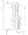
- the device 10 shown is for preheating scrap (symbolized in various shapes and numeral S in Fig. 1b ) before the scrap S is charge into in electric arc furnace E.
- the device comprises a bottom 12, side walls 14 and a ceiling 16, all together forming a tunnel with a channel 18 extending between an entry port 20 (inlet) and an exit port 22 (outlet) in a longitudinal direction L-L.
- a conveyor 24 extends through said channel 18 in said longitudinal direction L-L. Conveyor 24 is cooled from below by air (cooling nozzles are symbolized by numeral 24k).
- Section 241 As may been seen from a combination of Fig. 1a,1b conveyor 24 comprises different sections. Section 24-1, starting at the entry port 20, has a width of 3m, while the inner width of the channel 18 is slightly larger. Section 24-1 extends up to about 2/3 of the total length of the transportation conveyor at a certain level (L1) defining a surface (24s) for the scrap S to be treated.
- L1 certain level
- section 24-1 a constructional means designed as a rod 34 is installed, which rod 34 is fixed at the ceiling 16 and protrudes into the scrap layer in order to urge the scrap pieces to tilt and thereby to change their position and provide a different surface area towards heating element 28.
- a second conveyor section 24-2 follows section 24-1 in the longitudinal direction L-L towards the exit 22 of said device, but at a lower level (L2) thus forming a mixing step M there between.
- This step M is transverse to the longitudinal axis L-L of the device, but angled sections (symbolized in dotted lines) may be provided as well to increase the mixing effect described above.
- Scrap S, transported on section 24-1 drops down onto section 24-2, thereby changing its orientation and thus presenting another surface area towards the ceiling 16 of said device.
- Scrap pieces S in different layers may exchange their position at such step,
- steps or other means for varying the position of individual scrap pieces may be installed in said device 10.
- Section 24-2 has three sub-sections, namely 24-2a, similar to section 24-1, section 24-2b, following section 24-2a and section 24-2c following section 24-2b and continuing up to the exit door 22 of channel 18.
- the conveyor width is reduced in section 24-2b, starting with the same width as section 24-1 and ending with the same width as sub-section 24-2c, the latter being about 1,5m or half the width of section 24-1.
- the scraps S is heated along its journey through said device as follows: in the first half of the channel 18 (from the entry 20 towards exit 22) porous ceramic radiation burners 28 each with an active ceramic radiation surface of about 1m 2 are installed just below the ceiling 16 and at a short distance to the scrap S. This arrangement allows a very effective heat transfer.
- the radiation burners 28 are fired with. gas.
- Exhaust gases are drawn off from the rear side 38a of these heating elements (radiation burners 28) and fed via inlet ports 30a of a duct 30 to different outlet ports, designed as nozzles 32a, 32b in the sidewalls 14 of the device, above conveyor 20 and slightly above the scrap (layer).
- nozzles 32a, 32b for recycling exhaust gases (fumes) from the radiation burners 28 into the channel 18 in order to support the pre-heating of the scrap S are installed in the transition regions between sections 24-2a and 24-2b and shortly before the transition region between sub-sections 24-2b and 24-2c.
Landscapes
- Engineering & Computer Science (AREA)
- Mechanical Engineering (AREA)
- General Engineering & Computer Science (AREA)
- Furnace Details (AREA)
- Manufacture And Refinement Of Metals (AREA)
- Vertical, Hearth, Or Arc Furnaces (AREA)
- Furnace Charging Or Discharging (AREA)
Priority Applications (6)
| Application Number | Priority Date | Filing Date | Title |
|---|---|---|---|
| EP11173683.1A EP2546593B1 (fr) | 2011-07-12 | 2011-07-12 | Dispositif pour le transfert de matériau métallurgique |
| RU2014104777/02A RU2602573C2 (ru) | 2011-07-12 | 2012-06-28 | Устройство для предварительного нагрева транспортируемого скрапа |
| US14/128,832 US9551531B2 (en) | 2011-07-12 | 2012-06-28 | Device for transferring a metallurgical material |
| PCT/EP2012/062613 WO2013007533A1 (fr) | 2011-07-12 | 2012-06-28 | Dispositif pour le transfert d'un matériau métallurgique |
| BR112014000229A BR112014000229A2 (pt) | 2011-07-12 | 2012-06-28 | dispositivo para a transferência de um material metalúrgico |
| CN201280033973.4A CN103797324B (zh) | 2011-07-12 | 2012-06-28 | 用于传输冶金材料的装置 |
Applications Claiming Priority (1)
| Application Number | Priority Date | Filing Date | Title |
|---|---|---|---|
| EP11173683.1A EP2546593B1 (fr) | 2011-07-12 | 2011-07-12 | Dispositif pour le transfert de matériau métallurgique |
Publications (2)
| Publication Number | Publication Date |
|---|---|
| EP2546593A1 true EP2546593A1 (fr) | 2013-01-16 |
| EP2546593B1 EP2546593B1 (fr) | 2015-03-04 |
Family
ID=45000019
Family Applications (1)
| Application Number | Title | Priority Date | Filing Date |
|---|---|---|---|
| EP11173683.1A Active EP2546593B1 (fr) | 2011-07-12 | 2011-07-12 | Dispositif pour le transfert de matériau métallurgique |
Country Status (6)
| Country | Link |
|---|---|
| US (1) | US9551531B2 (fr) |
| EP (1) | EP2546593B1 (fr) |
| CN (1) | CN103797324B (fr) |
| BR (1) | BR112014000229A2 (fr) |
| RU (1) | RU2602573C2 (fr) |
| WO (1) | WO2013007533A1 (fr) |
Cited By (1)
| Publication number | Priority date | Publication date | Assignee | Title |
|---|---|---|---|---|
| WO2015181781A1 (fr) | 2014-05-30 | 2015-12-03 | Danieli & C. Officine Meccaniche S.P.A. | Appareil permettant de déplacer et de préchauffer un matériau métallique |
Families Citing this family (3)
| Publication number | Priority date | Publication date | Assignee | Title |
|---|---|---|---|---|
| EP2546593B1 (fr) * | 2011-07-12 | 2015-03-04 | SMS Concast Italia S.p.A. | Dispositif pour le transfert de matériau métallurgique |
| GEP20166469B (en) * | 2015-02-20 | 2016-04-25 | Method for melting steel with one aggregate and aggregate | |
| ES2997484T3 (en) * | 2018-07-18 | 2025-02-17 | Tenova Spa | Improved process and plant for preheating a metal charge fed in continuous to an electric melting furnace |
Citations (6)
| Publication number | Priority date | Publication date | Assignee | Title |
|---|---|---|---|---|
| US4202661A (en) * | 1976-12-06 | 1980-05-13 | Thermo Electron Corporation | Jet implement radiation furnace, method and apparatus |
| JPS5953620A (ja) * | 1982-09-21 | 1984-03-28 | Sumitomo Metal Ind Ltd | 加熱炉 |
| DE3616871A1 (de) * | 1985-05-27 | 1986-11-27 | Daidotokushuko K.K., Nagoya, Aichi | Rollenherd-vakuumofen |
| EP0247923A1 (fr) * | 1986-05-29 | 1987-12-02 | Intersteel Technology, Inc. | Procédé et dispositif de chargement continu d'un four d'aciérie |
| US5400358A (en) | 1992-10-13 | 1995-03-21 | Consteel, S.A. | Continuous scrap preheating |
| DE102009047751A1 (de) | 2009-04-24 | 2010-11-18 | Gvp Gesellschaft Zur Vermarktung Der Porenbrennertechnik Mbh | Brenneranordnung |
Family Cites Families (10)
| Publication number | Priority date | Publication date | Assignee | Title |
|---|---|---|---|---|
| US4113977A (en) | 1977-08-19 | 1978-09-12 | Brown Boveri Corporation | Preheating system with gas recirculation |
| SU1523869A1 (ru) * | 1988-04-13 | 1989-11-23 | Украинский Государственный Институт По Проектированию Металлургических Заводов "Укргипромез" | Устройство дл нагрева и загрузки скрапа в конвертер |
| EP0627606B1 (fr) * | 1993-05-10 | 1999-08-04 | Maschinenfabrik Gustav Eirich | Dispositif de préchauffage |
| US5581574A (en) | 1993-11-05 | 1996-12-03 | Technology Holdings, Inc. | Method and apparatus for conditioning and using furnace off-gases in a scrap preheating apparatus |
| CA2178763C (fr) | 1995-06-06 | 1999-04-20 | Brian W. Le Gras | Enceinte de rechauffage de lingots et tube de transfert de metal en fusion pour installation de fusion et de coulee d'aluminium |
| JP4724546B2 (ja) | 2005-12-08 | 2011-07-13 | 新日本製鐵株式会社 | スクラップの予熱処理装置及び予熱処理方法 |
| DE102008004775A1 (de) | 2008-01-16 | 2009-07-23 | Krones Ag | Vorrichtung zum Transportieren von Gegenständen |
| CN201662331U (zh) | 2010-02-01 | 2010-12-01 | 中冶赛迪工程技术股份有限公司 | 一种电炉加料和预热装置 |
| EP2546593B1 (fr) * | 2011-07-12 | 2015-03-04 | SMS Concast Italia S.p.A. | Dispositif pour le transfert de matériau métallurgique |
| EP2546592B1 (fr) * | 2011-07-12 | 2015-03-11 | SMS Concast Italia S.p.A. | Dispositif pour le transfert de matériau métallurgique |
-
2011
- 2011-07-12 EP EP11173683.1A patent/EP2546593B1/fr active Active
-
2012
- 2012-06-28 US US14/128,832 patent/US9551531B2/en active Active
- 2012-06-28 RU RU2014104777/02A patent/RU2602573C2/ru active
- 2012-06-28 WO PCT/EP2012/062613 patent/WO2013007533A1/fr not_active Ceased
- 2012-06-28 CN CN201280033973.4A patent/CN103797324B/zh active Active
- 2012-06-28 BR BR112014000229A patent/BR112014000229A2/pt not_active Application Discontinuation
Patent Citations (6)
| Publication number | Priority date | Publication date | Assignee | Title |
|---|---|---|---|---|
| US4202661A (en) * | 1976-12-06 | 1980-05-13 | Thermo Electron Corporation | Jet implement radiation furnace, method and apparatus |
| JPS5953620A (ja) * | 1982-09-21 | 1984-03-28 | Sumitomo Metal Ind Ltd | 加熱炉 |
| DE3616871A1 (de) * | 1985-05-27 | 1986-11-27 | Daidotokushuko K.K., Nagoya, Aichi | Rollenherd-vakuumofen |
| EP0247923A1 (fr) * | 1986-05-29 | 1987-12-02 | Intersteel Technology, Inc. | Procédé et dispositif de chargement continu d'un four d'aciérie |
| US5400358A (en) | 1992-10-13 | 1995-03-21 | Consteel, S.A. | Continuous scrap preheating |
| DE102009047751A1 (de) | 2009-04-24 | 2010-11-18 | Gvp Gesellschaft Zur Vermarktung Der Porenbrennertechnik Mbh | Brenneranordnung |
Cited By (3)
| Publication number | Priority date | Publication date | Assignee | Title |
|---|---|---|---|---|
| WO2015181781A1 (fr) | 2014-05-30 | 2015-12-03 | Danieli & C. Officine Meccaniche S.P.A. | Appareil permettant de déplacer et de préchauffer un matériau métallique |
| RU2680045C2 (ru) * | 2014-05-30 | 2019-02-14 | Даньели И К. Оффичине Мекканике С.П.А. | Устройство для транспортировки и предварительного нагревания металлического материала |
| US10584394B2 (en) | 2014-05-30 | 2020-03-10 | Danieli & C. Officine Meccaniche Spa | Apparatus to move and preheat metal material |
Also Published As
| Publication number | Publication date |
|---|---|
| EP2546593B1 (fr) | 2015-03-04 |
| RU2602573C2 (ru) | 2016-11-20 |
| RU2014104777A (ru) | 2015-08-20 |
| US9551531B2 (en) | 2017-01-24 |
| CN103797324A (zh) | 2014-05-14 |
| CN103797324B (zh) | 2016-06-08 |
| BR112014000229A2 (pt) | 2017-02-21 |
| US20150130120A1 (en) | 2015-05-14 |
| WO2013007533A1 (fr) | 2013-01-17 |
Similar Documents
| Publication | Publication Date | Title |
|---|---|---|
| EP2546592B1 (fr) | Dispositif pour le transfert de matériau métallurgique | |
| US4012190A (en) | Annealing lehr | |
| EP2546593B1 (fr) | Dispositif pour le transfert de matériau métallurgique | |
| GB1589609A (en) | Preheating furnace | |
| MX2008000424A (es) | Aparato para la combustion de gas que sale de un horno, para el precalentamiento de fragmentos que entran al mismo horno y procesos relacionados. | |
| KR20080028767A (ko) | 빌릿 가열 장치 | |
| EP2464940B1 (fr) | Système utilisant de la chaleur perdue et procédé pour le préchauffage de ferraille | |
| EP3027991B1 (fr) | Module de chauffage à rayonnement pour fours de cuisson de produits céramiques à cycle continu | |
| US5667378A (en) | Low profile kiln apparatus | |
| US6767206B2 (en) | Arrangement and method for heating gas in a gas duct in connection with continuously operated sintering | |
| EP2004867B1 (fr) | Dispositif et procede de chauffage en equipement de frittage continu | |
| JP2974629B2 (ja) | 雰囲気循環式連続熱処理炉の操業方法 | |
| EP1083396B1 (fr) | Four pour la cuisson d'articles industriels | |
| CN104583700B (zh) | 将加热的金属材料连续供给至熔化炉的设备和方法 | |
| CA1205628A (fr) | Four de prechauffe de materiaux de forme allongee | |
| JPS6036587Y2 (ja) | 鋼材加熱炉における加熱装置 | |
| JPS6013035Y2 (ja) | 熱処理炉 | |
| EP3403040B1 (fr) | Four pour céramique à rendement amélioré | |
| JP2004163095A (ja) | 連続式焼成炉 | |
| JP2025077747A (ja) | 連続処理炉 | |
| JP2000087148A (ja) | ステンレス鋼帯の連続焼鈍炉 | |
| CN104583700A (zh) | 用于将加热的金属材料连续供给至用于生产钢的熔化炉的设备和相关方法 | |
| JP2019211185A (ja) | 加熱炉 | |
| GB2198507A (en) | Stock heating furnaces | |
| WO2023170721A1 (fr) | Appareil d'alimentation pour introduire une charge métallique dans un four de fusion |
Legal Events
| Date | Code | Title | Description |
|---|---|---|---|
| PUAI | Public reference made under article 153(3) epc to a published international application that has entered the european phase |
Free format text: ORIGINAL CODE: 0009012 |
|
| 17P | Request for examination filed |
Effective date: 20111229 |
|
| AK | Designated contracting states |
Kind code of ref document: A1 Designated state(s): AL AT BE BG CH CY CZ DE DK EE ES FI FR GB GR HR HU IE IS IT LI LT LU LV MC MK MT NL NO PL PT RO RS SE SI SK SM TR |
|
| AX | Request for extension of the european patent |
Extension state: BA ME |
|
| GRAP | Despatch of communication of intention to grant a patent |
Free format text: ORIGINAL CODE: EPIDOSNIGR1 |
|
| RIC1 | Information provided on ipc code assigned before grant |
Ipc: C21C 5/52 20060101ALI20140902BHEP Ipc: C21C 5/56 20060101ALI20140902BHEP Ipc: F27D 13/00 20060101AFI20140902BHEP |
|
| INTG | Intention to grant announced |
Effective date: 20140924 |
|
| GRAS | Grant fee paid |
Free format text: ORIGINAL CODE: EPIDOSNIGR3 |
|
| GRAA | (expected) grant |
Free format text: ORIGINAL CODE: 0009210 |
|
| AK | Designated contracting states |
Kind code of ref document: B1 Designated state(s): AL AT BE BG CH CY CZ DE DK EE ES FI FR GB GR HR HU IE IS IT LI LT LU LV MC MK MT NL NO PL PT RO RS SE SI SK SM TR |
|
| REG | Reference to a national code |
Ref country code: GB Ref legal event code: FG4D |
|
| REG | Reference to a national code |
Ref country code: CH Ref legal event code: EP |
|
| REG | Reference to a national code |
Ref country code: IE Ref legal event code: FG4D |
|
| REG | Reference to a national code |
Ref country code: AT Ref legal event code: REF Ref document number: 714242 Country of ref document: AT Kind code of ref document: T Effective date: 20150415 |
|
| REG | Reference to a national code |
Ref country code: DE Ref legal event code: R096 Ref document number: 602011014262 Country of ref document: DE Effective date: 20150416 |
|
| REG | Reference to a national code |
Ref country code: CH Ref legal event code: NV Representative=s name: JACOBACCI AND PARTNERS SA, CH |
|
| REG | Reference to a national code |
Ref country code: NL Ref legal event code: VDEP Effective date: 20150304 |
|
| PG25 | Lapsed in a contracting state [announced via postgrant information from national office to epo] |
Ref country code: ES Free format text: LAPSE BECAUSE OF FAILURE TO SUBMIT A TRANSLATION OF THE DESCRIPTION OR TO PAY THE FEE WITHIN THE PRESCRIBED TIME-LIMIT Effective date: 20150304 Ref country code: LT Free format text: LAPSE BECAUSE OF FAILURE TO SUBMIT A TRANSLATION OF THE DESCRIPTION OR TO PAY THE FEE WITHIN THE PRESCRIBED TIME-LIMIT Effective date: 20150304 Ref country code: NO Free format text: LAPSE BECAUSE OF FAILURE TO SUBMIT A TRANSLATION OF THE DESCRIPTION OR TO PAY THE FEE WITHIN THE PRESCRIBED TIME-LIMIT Effective date: 20150604 Ref country code: HR Free format text: LAPSE BECAUSE OF FAILURE TO SUBMIT A TRANSLATION OF THE DESCRIPTION OR TO PAY THE FEE WITHIN THE PRESCRIBED TIME-LIMIT Effective date: 20150304 Ref country code: FI Free format text: LAPSE BECAUSE OF FAILURE TO SUBMIT A TRANSLATION OF THE DESCRIPTION OR TO PAY THE FEE WITHIN THE PRESCRIBED TIME-LIMIT Effective date: 20150304 Ref country code: SE Free format text: LAPSE BECAUSE OF FAILURE TO SUBMIT A TRANSLATION OF THE DESCRIPTION OR TO PAY THE FEE WITHIN THE PRESCRIBED TIME-LIMIT Effective date: 20150304 |
|
| REG | Reference to a national code |
Ref country code: LT Ref legal event code: MG4D |
|
| PG25 | Lapsed in a contracting state [announced via postgrant information from national office to epo] |
Ref country code: RS Free format text: LAPSE BECAUSE OF FAILURE TO SUBMIT A TRANSLATION OF THE DESCRIPTION OR TO PAY THE FEE WITHIN THE PRESCRIBED TIME-LIMIT Effective date: 20150304 Ref country code: LV Free format text: LAPSE BECAUSE OF FAILURE TO SUBMIT A TRANSLATION OF THE DESCRIPTION OR TO PAY THE FEE WITHIN THE PRESCRIBED TIME-LIMIT Effective date: 20150304 Ref country code: GR Free format text: LAPSE BECAUSE OF FAILURE TO SUBMIT A TRANSLATION OF THE DESCRIPTION OR TO PAY THE FEE WITHIN THE PRESCRIBED TIME-LIMIT Effective date: 20150605 |
|
| PG25 | Lapsed in a contracting state [announced via postgrant information from national office to epo] |
Ref country code: NL Free format text: LAPSE BECAUSE OF FAILURE TO SUBMIT A TRANSLATION OF THE DESCRIPTION OR TO PAY THE FEE WITHIN THE PRESCRIBED TIME-LIMIT Effective date: 20150304 |
|
| PG25 | Lapsed in a contracting state [announced via postgrant information from national office to epo] |
Ref country code: RO Free format text: LAPSE BECAUSE OF FAILURE TO SUBMIT A TRANSLATION OF THE DESCRIPTION OR TO PAY THE FEE WITHIN THE PRESCRIBED TIME-LIMIT Effective date: 20150304 Ref country code: SK Free format text: LAPSE BECAUSE OF FAILURE TO SUBMIT A TRANSLATION OF THE DESCRIPTION OR TO PAY THE FEE WITHIN THE PRESCRIBED TIME-LIMIT Effective date: 20150304 Ref country code: EE Free format text: LAPSE BECAUSE OF FAILURE TO SUBMIT A TRANSLATION OF THE DESCRIPTION OR TO PAY THE FEE WITHIN THE PRESCRIBED TIME-LIMIT Effective date: 20150304 Ref country code: PT Free format text: LAPSE BECAUSE OF FAILURE TO SUBMIT A TRANSLATION OF THE DESCRIPTION OR TO PAY THE FEE WITHIN THE PRESCRIBED TIME-LIMIT Effective date: 20150706 Ref country code: CZ Free format text: LAPSE BECAUSE OF FAILURE TO SUBMIT A TRANSLATION OF THE DESCRIPTION OR TO PAY THE FEE WITHIN THE PRESCRIBED TIME-LIMIT Effective date: 20150304 |
|
| PG25 | Lapsed in a contracting state [announced via postgrant information from national office to epo] |
Ref country code: IS Free format text: LAPSE BECAUSE OF FAILURE TO SUBMIT A TRANSLATION OF THE DESCRIPTION OR TO PAY THE FEE WITHIN THE PRESCRIBED TIME-LIMIT Effective date: 20150704 Ref country code: PL Free format text: LAPSE BECAUSE OF FAILURE TO SUBMIT A TRANSLATION OF THE DESCRIPTION OR TO PAY THE FEE WITHIN THE PRESCRIBED TIME-LIMIT Effective date: 20150304 |
|
| REG | Reference to a national code |
Ref country code: DE Ref legal event code: R097 Ref document number: 602011014262 Country of ref document: DE |
|
| PLBE | No opposition filed within time limit |
Free format text: ORIGINAL CODE: 0009261 |
|
| STAA | Information on the status of an ep patent application or granted ep patent |
Free format text: STATUS: NO OPPOSITION FILED WITHIN TIME LIMIT |
|
| PG25 | Lapsed in a contracting state [announced via postgrant information from national office to epo] |
Ref country code: DK Free format text: LAPSE BECAUSE OF FAILURE TO SUBMIT A TRANSLATION OF THE DESCRIPTION OR TO PAY THE FEE WITHIN THE PRESCRIBED TIME-LIMIT Effective date: 20150304 |
|
| 26N | No opposition filed |
Effective date: 20151207 |
|
| REG | Reference to a national code |
Ref country code: AT Ref legal event code: UEP Ref document number: 714242 Country of ref document: AT Kind code of ref document: T Effective date: 20150304 |
|
| PG25 | Lapsed in a contracting state [announced via postgrant information from national office to epo] |
Ref country code: SI Free format text: LAPSE BECAUSE OF FAILURE TO SUBMIT A TRANSLATION OF THE DESCRIPTION OR TO PAY THE FEE WITHIN THE PRESCRIBED TIME-LIMIT Effective date: 20150304 Ref country code: MC Free format text: LAPSE BECAUSE OF FAILURE TO SUBMIT A TRANSLATION OF THE DESCRIPTION OR TO PAY THE FEE WITHIN THE PRESCRIBED TIME-LIMIT Effective date: 20150304 |
|
| GBPC | Gb: european patent ceased through non-payment of renewal fee |
Effective date: 20150712 |
|
| PG25 | Lapsed in a contracting state [announced via postgrant information from national office to epo] |
Ref country code: LU Free format text: LAPSE BECAUSE OF FAILURE TO SUBMIT A TRANSLATION OF THE DESCRIPTION OR TO PAY THE FEE WITHIN THE PRESCRIBED TIME-LIMIT Effective date: 20150712 |
|
| REG | Reference to a national code |
Ref country code: IE Ref legal event code: MM4A |
|
| PG25 | Lapsed in a contracting state [announced via postgrant information from national office to epo] |
Ref country code: GB Free format text: LAPSE BECAUSE OF NON-PAYMENT OF DUE FEES Effective date: 20150712 |
|
| REG | Reference to a national code |
Ref country code: FR Ref legal event code: ST Effective date: 20160331 |
|
| PG25 | Lapsed in a contracting state [announced via postgrant information from national office to epo] |
Ref country code: FR Free format text: LAPSE BECAUSE OF NON-PAYMENT OF DUE FEES Effective date: 20150731 |
|
| PG25 | Lapsed in a contracting state [announced via postgrant information from national office to epo] |
Ref country code: IE Free format text: LAPSE BECAUSE OF NON-PAYMENT OF DUE FEES Effective date: 20150712 |
|
| PG25 | Lapsed in a contracting state [announced via postgrant information from national office to epo] |
Ref country code: BE Free format text: LAPSE BECAUSE OF FAILURE TO SUBMIT A TRANSLATION OF THE DESCRIPTION OR TO PAY THE FEE WITHIN THE PRESCRIBED TIME-LIMIT Effective date: 20150304 |
|
| PG25 | Lapsed in a contracting state [announced via postgrant information from national office to epo] |
Ref country code: MT Free format text: LAPSE BECAUSE OF FAILURE TO SUBMIT A TRANSLATION OF THE DESCRIPTION OR TO PAY THE FEE WITHIN THE PRESCRIBED TIME-LIMIT Effective date: 20150304 |
|
| PG25 | Lapsed in a contracting state [announced via postgrant information from national office to epo] |
Ref country code: SM Free format text: LAPSE BECAUSE OF FAILURE TO SUBMIT A TRANSLATION OF THE DESCRIPTION OR TO PAY THE FEE WITHIN THE PRESCRIBED TIME-LIMIT Effective date: 20150304 Ref country code: HU Free format text: LAPSE BECAUSE OF FAILURE TO SUBMIT A TRANSLATION OF THE DESCRIPTION OR TO PAY THE FEE WITHIN THE PRESCRIBED TIME-LIMIT; INVALID AB INITIO Effective date: 20110712 Ref country code: BG Free format text: LAPSE BECAUSE OF FAILURE TO SUBMIT A TRANSLATION OF THE DESCRIPTION OR TO PAY THE FEE WITHIN THE PRESCRIBED TIME-LIMIT Effective date: 20150304 |
|
| PG25 | Lapsed in a contracting state [announced via postgrant information from national office to epo] |
Ref country code: CY Free format text: LAPSE BECAUSE OF FAILURE TO SUBMIT A TRANSLATION OF THE DESCRIPTION OR TO PAY THE FEE WITHIN THE PRESCRIBED TIME-LIMIT Effective date: 20150304 |
|
| PG25 | Lapsed in a contracting state [announced via postgrant information from national office to epo] |
Ref country code: TR Free format text: LAPSE BECAUSE OF FAILURE TO SUBMIT A TRANSLATION OF THE DESCRIPTION OR TO PAY THE FEE WITHIN THE PRESCRIBED TIME-LIMIT Effective date: 20150304 |
|
| PG25 | Lapsed in a contracting state [announced via postgrant information from national office to epo] |
Ref country code: MK Free format text: LAPSE BECAUSE OF FAILURE TO SUBMIT A TRANSLATION OF THE DESCRIPTION OR TO PAY THE FEE WITHIN THE PRESCRIBED TIME-LIMIT Effective date: 20150304 |
|
| PG25 | Lapsed in a contracting state [announced via postgrant information from national office to epo] |
Ref country code: AL Free format text: LAPSE BECAUSE OF FAILURE TO SUBMIT A TRANSLATION OF THE DESCRIPTION OR TO PAY THE FEE WITHIN THE PRESCRIBED TIME-LIMIT Effective date: 20150304 |
|
| PGFP | Annual fee paid to national office [announced via postgrant information from national office to epo] |
Ref country code: CH Payment date: 20180719 Year of fee payment: 8 |
|
| REG | Reference to a national code |
Ref country code: CH Ref legal event code: PL |
|
| PG25 | Lapsed in a contracting state [announced via postgrant information from national office to epo] |
Ref country code: LI Free format text: LAPSE BECAUSE OF NON-PAYMENT OF DUE FEES Effective date: 20190731 Ref country code: CH Free format text: LAPSE BECAUSE OF NON-PAYMENT OF DUE FEES Effective date: 20190731 |
|
| P01 | Opt-out of the competence of the unified patent court (upc) registered |
Effective date: 20230524 |
|
| PGFP | Annual fee paid to national office [announced via postgrant information from national office to epo] |
Ref country code: IT Payment date: 20250505 Year of fee payment: 15 |
|
| PGFP | Annual fee paid to national office [announced via postgrant information from national office to epo] |
Ref country code: DE Payment date: 20250725 Year of fee payment: 15 |
|
| PGFP | Annual fee paid to national office [announced via postgrant information from national office to epo] |
Ref country code: AT Payment date: 20250718 Year of fee payment: 15 |