EP2546594A1 - Wärmetauscher, insbesondere für Kraftfahrzeug, der als thermelektrische Vorrichtung fungiert - Google Patents
Wärmetauscher, insbesondere für Kraftfahrzeug, der als thermelektrische Vorrichtung fungiert Download PDFInfo
- Publication number
- EP2546594A1 EP2546594A1 EP12175995A EP12175995A EP2546594A1 EP 2546594 A1 EP2546594 A1 EP 2546594A1 EP 12175995 A EP12175995 A EP 12175995A EP 12175995 A EP12175995 A EP 12175995A EP 2546594 A1 EP2546594 A1 EP 2546594A1
- Authority
- EP
- European Patent Office
- Prior art keywords
- spacers
- fluid
- exchanger according
- tubes
- zone
- Prior art date
- Legal status (The legal status is an assumption and is not a legal conclusion. Google has not performed a legal analysis and makes no representation as to the accuracy of the status listed.)
- Withdrawn
Links
Images

Classifications
-
- F—MECHANICAL ENGINEERING; LIGHTING; HEATING; WEAPONS; BLASTING
- F28—HEAT EXCHANGE IN GENERAL
- F28D—HEAT-EXCHANGE APPARATUS, NOT PROVIDED FOR IN ANOTHER SUBCLASS, IN WHICH THE HEAT-EXCHANGE MEDIA DO NOT COME INTO DIRECT CONTACT
- F28D1/00—Heat-exchange apparatus having stationary conduit assemblies for one heat-exchange medium only, the media being in contact with different sides of the conduit wall, in which the other heat-exchange medium is a large body of fluid, e.g. domestic or motor car radiators
- F28D1/02—Heat-exchange apparatus having stationary conduit assemblies for one heat-exchange medium only, the media being in contact with different sides of the conduit wall, in which the other heat-exchange medium is a large body of fluid, e.g. domestic or motor car radiators with heat-exchange conduits immersed in the body of fluid
- F28D1/04—Heat-exchange apparatus having stationary conduit assemblies for one heat-exchange medium only, the media being in contact with different sides of the conduit wall, in which the other heat-exchange medium is a large body of fluid, e.g. domestic or motor car radiators with heat-exchange conduits immersed in the body of fluid with tubular conduits
-
- F—MECHANICAL ENGINEERING; LIGHTING; HEATING; WEAPONS; BLASTING
- F01—MACHINES OR ENGINES IN GENERAL; ENGINE PLANTS IN GENERAL; STEAM ENGINES
- F01N—GAS-FLOW SILENCERS OR EXHAUST APPARATUS FOR MACHINES OR ENGINES IN GENERAL; GAS-FLOW SILENCERS OR EXHAUST APPARATUS FOR INTERNAL-COMBUSTION ENGINES
- F01N5/00—Exhaust or silencing apparatus combined or associated with devices profiting by exhaust energy
- F01N5/02—Exhaust or silencing apparatus combined or associated with devices profiting by exhaust energy the devices using heat
- F01N5/025—Exhaust or silencing apparatus combined or associated with devices profiting by exhaust energy the devices using heat the device being thermoelectric generators
-
- Y—GENERAL TAGGING OF NEW TECHNOLOGICAL DEVELOPMENTS; GENERAL TAGGING OF CROSS-SECTIONAL TECHNOLOGIES SPANNING OVER SEVERAL SECTIONS OF THE IPC; TECHNICAL SUBJECTS COVERED BY FORMER USPC CROSS-REFERENCE ART COLLECTIONS [XRACs] AND DIGESTS
- Y02—TECHNOLOGIES OR APPLICATIONS FOR MITIGATION OR ADAPTATION AGAINST CLIMATE CHANGE
- Y02T—CLIMATE CHANGE MITIGATION TECHNOLOGIES RELATED TO TRANSPORTATION
- Y02T10/00—Road transport of goods or passengers
- Y02T10/10—Internal combustion engine [ICE] based vehicles
- Y02T10/12—Improving ICE efficiencies
Definitions
- the present invention relates to a heat exchanger, especially for a motor vehicle, making thermoelectric device.
- thermoelectric devices using so-called electrical thermo elements, for generating an electric current in the presence of a temperature gradient between two of their opposite faces according to the phenomenon known as the Seebeck effect.
- These devices comprise a beam formed of a stack of first tubes, intended for the circulation of the exhaust gases of an engine, and second tubes for the circulation of a heat transfer fluid of a cooling circuit.
- the electrical thermo elements are sandwiched between the tubes so as to be subjected to a temperature gradient from the temperature difference between the hot exhaust gases and the cold cooling fluid.
- Such devices are particularly interesting because they make it possible to produce electricity from a conversion of the heat coming from the exhaust gases of the engine. They thus offer the possibility of reducing the fuel consumption of the vehicle by replacing, at least partially, the alternator usually provided therein to generate electricity from a belt driven by the engine crankshaft. .
- thermoelectric devices use a beam integrally dedicated to the creation of the thermal gradient necessary for the operation of the thermoelectric elements.
- the present invention starts from the observation that many exchangers are already available in motor vehicles and that the structure of their beam is close to that of a beam of a thermoelectric device. In addition, their operation is based on another common point namely the presence of two fluids at different temperatures in contact with the beam. In the case of an exchanger, it is cool / heat one with the other. In the case of a thermoelectric device, as said above, it is a question of creating the temperature gradient necessary for the operation of the thermoelectric elements.
- the invention proposes for this purpose a heat exchanger, in particular for a motor vehicle, comprising so-called electric thermo elements, making it possible to generate an electric current in the presence of a temperature gradient, and a beam comprising a first zone configured to allow a heat exchange between a first fluid, said to be hot, and a second fluid, said to be cold, and a second zone configured to allow the generation of said electric current by thermally connecting the electric thermoelectric elements with components of the beam from said first part said components being in heat exchange relationship with at least one of said fluids.
- thermoelectric elements This provides both, with the aid of a single beam, a heat exchange function for cooling the hot fluid and heating the cold fluid, on the one hand, and on the other hand , a function of supplying at least one of the hot or cold sources necessary for the operation of the thermoelectric elements.
- the hot fluid may be the fluid of a cooling loop of the engine of the vehicle, in particular taken out of the engine, and the cold fluid the ambient air.
- the exchanger will then, in particular, configured to be located at a vehicle front face so as to be traversed by the flow of air flowing through a radiator grille of the vehicle.
- thermoelectric elements By associating the electric thermo elements with fins, it facilitates the intimacy of the contact between them and the components of the device in contact with which they must be to be subjected to a temperature gradient. Indeed, the obligation to establish a close connection between the thermoelectric elements and the component or components creating the temperature gradient necessary for their operation is no longer worn, or in any case no longer only, by circulation tubes. fluid but by a specific component, the fins, which can be chosen for this.
- said electric thermo elements are pre-assembled in module. This will facilitate their assembly in the exchanger.
- the device according to the invention may further comprise collecting boxes for the hot fluid in which the tubes of the beam open at their ends.
- the invention relates to a heat exchanger, in particular for a motor vehicle, comprising a beam 1 allowing, in a first function, a heat exchange between a first fluid, said hot and a second fluid, said cold.
- the exchanger according to the invention is thus intended to accommodate two fluids input, the first, namely the hot fluid, having a higher temperature than the second, namely the cold fluid.
- the hot fluid may be the cooling fluid of a cooling loop of the vehicle engine and the cold fluid a flow of ambient air from the front of the vehicle, through its calender.
- Other types of fluids are however possible, especially other types of hot fluid. It may be, in particular, hot fluids whose circuit passes through the front of the vehicle to allow their cooling and / or a phase change.
- the exchanger is configured, in particular, so that the hot fluid passes through the exchanger in a first direction, illustrated by the arrow marked 3, and that the cold fluid passes through the exchanger in a second direction, illustrated by the arrow marked 2, in particular substantially perpendicular to the first direction 3. It is provided with manifolds 4 to distribute the hot liquid in the beam 1 and to collect said hot fluid exiting said beam 1.
- the manifolds here permit a circulation of the hot fluid U.
- the upper manifold 4 has an internal partition, not visible, dividing the box into two parts, each provided with a nozzle inlet / outlet of the hot fluid.
- the hot fluid thus enters a first part of the upper manifold by the inlet manifold, it travels the beam in the direction 3, downwards, on a first portion of the bundle, it is collected by the lower manifold 4 and distributed in the other part of the beam it travels upwards, in the direction 3, it is finally collected by the second part of the upper manifold 4 and out of the exchanger through its outlet manifold.
- the beam has, for example, a generally parallelepiped shape.
- the manifolds 4 are located on two opposite sides of the parallelogram.
- the beam has two opposite first faces 5, and two opposite second faces 6, connecting the boxes 4.
- the exchanger is configured so that the flow of cold fluid is perpendicular to the first faces 5.
- the dimension of the beam in the direction 2 the flow of cold fluid, namely its depth is, for example, less than the other dimensions of the beam, namely its width and height, that is to say the dimensions of the first faces 5.
- An exchanger thus configured is intended, for example, to be located on the front of the vehicle. It may however be placed in other locations of the vehicle. Similarly, the exchangers according to the invention may have other configurations while remaining intended to be located on the front of the vehicle.
- the device may include a beam 1 of tubes and fins, mechanical type.
- the tubes provided round and / or oblong, are parallel to each other and allow the passage of hot fluid. They opening through each of their end in the manifolds 4, through passage holes provided thereon, for example at the collector plates of said boxes.
- the fins, planned planes, are perpendicular to the tubes and traversed by them.
- the beam is configured so that the flow of cold fluid passes between the fins.
- the fins are held on the tubes and / or the tubes are held in the boxes, for example, by crimping.
- a seal is used to seal between the collector plates and the tubes at each of their through holes.
- the tubes may also be bundles of tubes and interleaved brazed.
- the tubes provided flat, are parallel to each other and allow the passage of hot fluid. They open at each end into the manifolds 4, through passage holes provided thereon, for example at the collector plates of said boxes.
- the interleaves, corrugated provided are arranged between the tubes and in contact with them by the peaks of their corrugations.
- the beam is configured so that the flow of cold fluid passes between the folds of the corrugations of said spacers.
- the spacers, the tubes and the collector boxes, or at least their collector plate, are assembled by brazing.
- the exchanger also comprises so-called electrical thermo elements for generating an electric current in the presence of a temperature gradient, not shown in these figures.
- substantially parallelepiped shaped elements generating an electric current, according to the Seebeck effect, when they are subjected to said gradient between two of their opposite faces, called active faces.
- Such elements allow the creation of an electric current in a load connected between said active faces.
- such elements consist, for example, of Bismuth and Tellurium (Bi 2 Te 3 ).
- the beam comprises a first zone 7 configured to allow said exchange of heat between the hot fluid and the cold fluid and a second zone 8 configured to allow the generation of said electric current by thermally connecting the electrical thermo elements with beam components from said first portion 7, said components being provided in heat exchange relationship with one at least said fluids.
- the invention allows a pooling of the means employed by proposing a thermal bridge between the first portion 7 and the second portion 8 of the bundle so that the thermal gradient required for the generation of electricity comes from the at least one fluid.
- said beam components from the first portion 7 are configured to be in thermal relationship, for example, with the hot fluid.
- the exchanger may comprise components specific to each of said first 7 and second 8 zones for the thermal connection between the cold fluid and the electric thermoelectric elements, on the one hand, and for the heat exchange between the fluid cold and the hot fluid, on the other hand.
- the first zone 7 and the second 8 may be traversed by the same cold fluid, independently of one another. This is for example the case with front-end exchangers in which part of the ambient air flow will pass through the first zone 8 of the beam and another part of the ambient air flow will pass through the second zone 7 while the hot fluid passing through the two zones 7, 8, namely the heat transfer fluid of the engine, will come from the same dispenser box and lead into the same manifold.
- the first zone 7 is provided downstream of the second zone 8 in the direction of circulation of the hot fluid, at least for part of said second zone 8.
- the first zone 7 and the second zone 8 are provided in parallel in the direction of circulation of the hot fluid.
- the second zone 8 will preferably be in the part of the beam 1 connected to the inlet pipe.
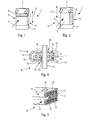
- Said beam comprises round and / or oval tubes 10 and first spacers 11 in heat exchange relation with said round and / or oval tubes 10, said round and / or oval tubes forming the beam components from said first part 7, not shown.
- Said second portion 8 of the beam further comprises second tabs 12 in heat exchange relation with the second fluid, said electric thermo elements 13 being positioned between said first 11 and second 12 spacers.
- thermo elements 13 it is therefore the first 11 and second 12 spacers that fulfill the function of establishing the thermal contact with the electric thermo elements 13.
- the first 11 and second 12 spacers are, for example, in the form of planar fins.
- fin means an element having two large opposite planar surfaces and of much smaller thickness than its width and its length, making it possible to establish a surface contact between said large surfaces and the thermoelectric elements 13 at the level of the their active faces 16.
- the fins are formed, for example, of aluminum and / or aluminum alloy.
- the first part of the bundle may also comprise flat fin-shaped spacers in heat exchange relation with the tubes, for example spacers identical to the first spacers 11 of the second part 8 of the beam.
- the second spacers 12 are configured, for example, to make a heat shield protecting the first spacers 11 of a flow of the second fluid.
- the second spacers 12 are pin-shaped 17, flanks 18 of each pin coming from either side of one of the first spacers 11.
- the flanks 18 of the pin 17 are connected, for example, by a elbow 19 defining said heat shield. In this way, as much heat as possible is concentrated towards the electric thermoelectric elements 13 and the greatest possible temperature gradient is ensured.
- the electric thermo elements 13 are located between the first spacers 11 and the sides 18 of the pins 17, in particular in several rows, here in a row of four elements. They are, for example, of millimeter size, even micrometer.
- Elastic studs 38 may be provided between the pins 17 so that the flanks 18 of the latter provide pressure on the electric thermoelectric elements 13. It is thus possible to absorb the mechanical stress generated by the expansion of the tubes 10 and the spacers 11, 12 .
- the second spacers 12 have an L-shaped, a flank 20 of the L coming to cap at least one of said first spacers 11. In this way, a result similar to that obtained with the bend 19 of the previous embodiment is obtained.
- thermoelectric elements 13 are located between the other side 21 of the L and the face 22 of the first spacer 11, provided vis-a-vis. They are arranged, in particular, in several ranks, here of four elements. Said thermoelectric elements 13 are again, for example, millimeter-sized or even micrometric.
- the first spacers 11 are provided with orifice 23 for the passage of the tubes 10 with which they are in contact.
- the second spacers 12 are provided with orifices 24 also allowing the passage of the tubes 10 but, this time, without contact to avoid any thermal bridge between the hot fluid and the cold fluid.
- the beam is, for example, brazed type. It comprises flat tubes 30 forming the beam components from said first portion 7, not shown, said second portion 8 of the beam further comprising tabs 31 in thermal relation with the second fluid, said electric thermo elements 13 being positioned between said flat tubes 30 and said spacers 31.
- the bundle comprises, for example, interleaves in the form of corrugated fins, as mentioned above, in heat exchange relation, on the one hand, with the second fluid and, on the other hand , with the tubes 30.
- the spacers 31 of the second portion 8 are configured, in particular, to make a heat shield protecting the flat tubes 30 of a flow of the second fluid, for the same reasons as in the previous embodiments.
- Said spacers 31 of the second portion 8 have, for example, a pin shape, parallel flanks 33 of the pin being slid between two adjacent tubes 30.
- the electric thermo elements 13 are, for example, between the tubes 30 and the parallel flanks 33 of the pins 32, in particular in several rows, here in a row of four elements. Said pins 32 may be provided prestressed to ensure a force for pressing the thermoelectric elements 13 against the flat tubes 30.
- the bottom 34 of said pins 32 may have cutouts 35 facilitating the passage 34 of the cold fluid through the second portion 8 of the beam.
- Said parallel flanks 33 are here extended by a skirt 36 so as to define the heat shield mentioned above.
- the skirt 36 comes to make screen in front of the contiguous tube 30.
- Each pin 32 is here provided with said skirt 36 at each of the parallel flanks 33, one of the skirts 36 of one of the pins 32 covering one of the skirts 36 of the pin 32 adjacent.
- the corrugated inserts of the first part have a height corresponding, for example, to the height between two adjacent tubes 30, that is to say, a height corresponding to that of two rows of electric thermo elements 13 supplemented by the height the pin between the two rows.
- Said hot tubes 30 are, for example, substantially flat tubes comprising two large opposite parallel faces on which the thermoelectric elements 13 are arranged by one of their active face, the other active face being in contact with one of the pins at their flank 33. They are, for example, aluminum and / or aluminum alloys.
- the spacers 31 of the second part 8, like those of the first part 7, may also be made of aluminum and / or aluminum alloys.
- the fins or spacers 11, 12, 31 are coated, for example, with an electrically insulating material and are provided, at their vis-a-vis face, with electrical thermoelectric elements.
- electrical thermoelectric elements one or more electrically conductive tracks, not shown, connecting, in series and / or in parallel, the electric thermo elements arranged on the insert.
- the flat tubes 30 may be coated at their large faces with a layer of electrically insulating material and are provided with electrically conductive tracks connecting, in series and / or in parallel, all or part of the thermoelectric elements arranged on the flat tubes 30.
- thermoelectric elements are, for example, for a first part, elements of a first type, called P, making it possible to establish an electric potential difference in a direction, called positive, when they are subjected to a gradient of given temperature and, for the other party, elements of a second type, said N, allowing the creation of an electrical potential difference in an opposite direction, said negative, when they are subjected to the same temperature gradient.
- thermoelectric elements will advantageously be associated in series, via said spacers 11, 12, 31 or flat tubes 30 with N type thermoelectric elements. All or part of the electric thermo elements of the same type may be associated in parallel.
- the electric thermo elements 13 may be pre-assembled in modules, ready to be inserted between the first and second spacers 11, 12 or the tubes 30 and the corresponding spacers 31.
- Said modules are, for example, under the form of rigid blocks and comprise two thermally conductive plates and having their own electrical circuit connecting the thermoelectric elements, the latter being provided between said two plates.
- Said thermoelectric elements are, in particular, embedded in a protective resin.
- the exchanger according to the invention may be used in place of a conventional exchanger, including front-end exchanger of the vehicle, such as radiators for vehicle engine cooling, charge air cooler or others.
- front-end exchanger of the vehicle such as radiators for vehicle engine cooling, charge air cooler or others.
- it can also be used in the exhaust line of the engine to both heat the cold fluid and generate electric current using the heat of the exhaust gas.
Landscapes
- Engineering & Computer Science (AREA)
- Mechanical Engineering (AREA)
- General Engineering & Computer Science (AREA)
- Chemical & Material Sciences (AREA)
- Combustion & Propulsion (AREA)
- Physics & Mathematics (AREA)
- Thermal Sciences (AREA)
- Heat-Exchange Devices With Radiators And Conduit Assemblies (AREA)
Applications Claiming Priority (1)
| Application Number | Priority Date | Filing Date | Title |
|---|---|---|---|
| FR1156333A FR2977931B1 (fr) | 2011-07-12 | 2011-07-12 | Echangeur de chaleur, notamment pour vehicule automobile, faisant dispositif thermo electrique |
Publications (1)
| Publication Number | Publication Date |
|---|---|
| EP2546594A1 true EP2546594A1 (de) | 2013-01-16 |
Family
ID=46458387
Family Applications (1)
| Application Number | Title | Priority Date | Filing Date |
|---|---|---|---|
| EP12175995A Withdrawn EP2546594A1 (de) | 2011-07-12 | 2012-07-11 | Wärmetauscher, insbesondere für Kraftfahrzeug, der als thermelektrische Vorrichtung fungiert |
Country Status (2)
| Country | Link |
|---|---|
| EP (1) | EP2546594A1 (de) |
| FR (1) | FR2977931B1 (de) |
Cited By (1)
| Publication number | Priority date | Publication date | Assignee | Title |
|---|---|---|---|---|
| WO2015197896A1 (es) * | 2014-06-26 | 2015-12-30 | Universitat De Girona | Dispositivo ventiloconvector |
Citations (3)
| Publication number | Priority date | Publication date | Assignee | Title |
|---|---|---|---|---|
| WO2007026432A1 (ja) * | 2005-08-31 | 2007-03-08 | Hitachi, Ltd. | Egrガス発電装置 |
| WO2009156361A1 (fr) * | 2008-06-24 | 2009-12-30 | Valeo Systemes Thermiques | Dispositif de generation d'energie electrique, faisceau d'echange de chaleur comprenant un tel dispositif et echangeur de chaleur comprenant un tel faisceau |
| US20110139398A1 (en) * | 2009-12-15 | 2011-06-16 | Mann+Hummel Gmbh | Cooling Device for a Vehicle |
-
2011
- 2011-07-12 FR FR1156333A patent/FR2977931B1/fr not_active Expired - Fee Related
-
2012
- 2012-07-11 EP EP12175995A patent/EP2546594A1/de not_active Withdrawn
Patent Citations (3)
| Publication number | Priority date | Publication date | Assignee | Title |
|---|---|---|---|---|
| WO2007026432A1 (ja) * | 2005-08-31 | 2007-03-08 | Hitachi, Ltd. | Egrガス発電装置 |
| WO2009156361A1 (fr) * | 2008-06-24 | 2009-12-30 | Valeo Systemes Thermiques | Dispositif de generation d'energie electrique, faisceau d'echange de chaleur comprenant un tel dispositif et echangeur de chaleur comprenant un tel faisceau |
| US20110139398A1 (en) * | 2009-12-15 | 2011-06-16 | Mann+Hummel Gmbh | Cooling Device for a Vehicle |
Cited By (2)
| Publication number | Priority date | Publication date | Assignee | Title |
|---|---|---|---|---|
| WO2015197896A1 (es) * | 2014-06-26 | 2015-12-30 | Universitat De Girona | Dispositivo ventiloconvector |
| ES2566878A1 (es) * | 2014-06-26 | 2016-04-15 | Universitat De Girona | Dispositivo ventiloconvector |
Also Published As
| Publication number | Publication date |
|---|---|
| FR2977931B1 (fr) | 2018-05-18 |
| FR2977931A1 (fr) | 2013-01-18 |
Similar Documents
| Publication | Publication Date | Title |
|---|---|---|
| EP2291871B1 (de) | Vorrichtung zur erzeugung von strom, wärmetauscherbündel mit derartiger vorrichtung und wärmetauscher mit derartigem bündel | |
| EP2622656A1 (de) | Verfahren zur herstellung einer thermoelektrischen vorrichtung, im besonderen zur erzeugung von strom bei einem kraftfahrzeug | |
| EP2622658B1 (de) | Thermoelektrische vorrichtung, im besonderen zur erzeugung von strom bei einem kraftfahrzeug | |
| EP2622657A1 (de) | Thermoelektrische vorrichtung, im besonderen zur stromerzeugung bei einem kraftfahrzeug | |
| EP2874191A2 (de) | Hybridvorrichtung, die ein thermoelektrisches Modul umfasst, insbesondere zur Stromerzeugung in einem Kraftfahrzeug, und Wärmetauscher | |
| EP2622659A1 (de) | Thermoelektrische vorrichtung, im besonderen zur stromerzeugung bei einem kraftfahrzeug | |
| EP2622655A1 (de) | Thermoelektrische vorrichtung, im besonderen zur stromerzeugung bei einem kraftfahrzeug | |
| EP2498309B1 (de) | Modul und thermoelektrische Vorrichtung, insbesondere zur Stromerzeugung in einem Kraftfahrzeug | |
| EP2936573B1 (de) | Anordnung mit einem thermoelektrischen element und vorrichtung zum elektrischen anschluss dieses thermoelektrischen elements sowie thermoelektrisches modul und thermoelektrische vorrichtung mit solch einer anordnung | |
| EP2912704A1 (de) | Thermoelektrisches modul und wärmetauscher mit solch einem modul | |
| EP2546594A1 (de) | Wärmetauscher, insbesondere für Kraftfahrzeug, der als thermelektrische Vorrichtung fungiert | |
| WO2014016323A1 (fr) | Module thermo électrique | |
| EP3017486A1 (de) | Thermoelektrische vorrichtung, insbesondere zur erzeugung von elektrischem strom in einem kraftfahrzeug | |
| FR3043187B1 (fr) | Batterie thermique a chaleur latente pour automobile | |
| EP2691995A1 (de) | Thermoelektrische anordnung und vorrichtung, insbesondere zur erzeugung von elektrischem strom in einem kraftfahrzeug | |
| EP2936574A1 (de) | Thermoelektrischer generator | |
| FR2980038A1 (fr) | Dispositif thermo electrique, notamment destine a generer un courant electrique dans un vehicule automobile | |
| FR2989831A1 (fr) | Dispositif thermo electrique, echangeur de chaleur comprenant un tel dispositif et procede de fabrication | |
| EP2880695A1 (de) | Verfahren zur herstellung eines thermoelektrischen moduls, insbesondere zur erzeugung eines elektrischen stromes in einem kraftfahrzeug und nach diesem verfahren hergestelltes thermoelektrisches modul | |
| FR2977376A1 (fr) | Procede de fabrication d'un dispositif thermo electrique, notamment destine a generer un courant electrique dans un vehicule automobile, et dispositif thermo electrique obtenu par un tel procede. | |
| FR2965405A1 (fr) | Procédé de fabrication d'un dispositif thermo électrique, notamment destine a générer un courant électrique dans un véhicule automobile. |
Legal Events
| Date | Code | Title | Description |
|---|---|---|---|
| PUAI | Public reference made under article 153(3) epc to a published international application that has entered the european phase |
Free format text: ORIGINAL CODE: 0009012 |
|
| AK | Designated contracting states |
Kind code of ref document: A1 Designated state(s): AL AT BE BG CH CY CZ DE DK EE ES FI FR GB GR HR HU IE IS IT LI LT LU LV MC MK MT NL NO PL PT RO RS SE SI SK SM TR |
|
| AX | Request for extension of the european patent |
Extension state: BA ME |
|
| 17P | Request for examination filed |
Effective date: 20130701 |
|
| RBV | Designated contracting states (corrected) |
Designated state(s): AL AT BE BG CH CY CZ DE DK EE ES FI FR GB GR HR HU IE IS IT LI LT LU LV MC MK MT NL NO PL PT RO RS SE SI SK SM TR |
|
| 17Q | First examination report despatched |
Effective date: 20180308 |
|
| STAA | Information on the status of an ep patent application or granted ep patent |
Free format text: STATUS: THE APPLICATION IS DEEMED TO BE WITHDRAWN |
|
| 18D | Application deemed to be withdrawn |
Effective date: 20190409 |