EP2546926A1 - Dispositif d'antenne - Google Patents
Dispositif d'antenne Download PDFInfo
- Publication number
- EP2546926A1 EP2546926A1 EP11174155A EP11174155A EP2546926A1 EP 2546926 A1 EP2546926 A1 EP 2546926A1 EP 11174155 A EP11174155 A EP 11174155A EP 11174155 A EP11174155 A EP 11174155A EP 2546926 A1 EP2546926 A1 EP 2546926A1
- Authority
- EP
- European Patent Office
- Prior art keywords
- antenna
- parasitic
- antennas
- supporting structure
- operate
- Prior art date
- Legal status (The legal status is an assumption and is not a legal conclusion. Google has not performed a legal analysis and makes no representation as to the accuracy of the status listed.)
- Withdrawn
Links
- 230000003071 parasitic effect Effects 0.000 claims abstract description 97
- 230000008878 coupling Effects 0.000 claims abstract description 26
- 238000010168 coupling process Methods 0.000 claims abstract description 26
- 238000005859 coupling reaction Methods 0.000 claims abstract description 26
- 238000004891 communication Methods 0.000 claims abstract description 23
- 238000000034 method Methods 0.000 claims abstract description 5
- 239000000758 substrate Substances 0.000 claims description 25
- 239000004020 conductor Substances 0.000 claims description 6
- PEZNEXFPRSOYPL-UHFFFAOYSA-N (bis(trifluoroacetoxy)iodo)benzene Chemical compound FC(F)(F)C(=O)OI(OC(=O)C(F)(F)F)C1=CC=CC=C1 PEZNEXFPRSOYPL-UHFFFAOYSA-N 0.000 claims 1
- 238000002955 isolation Methods 0.000 description 15
- 230000005404 monopole Effects 0.000 description 14
- 230000005855 radiation Effects 0.000 description 13
- 230000010287 polarization Effects 0.000 description 9
- 230000005672 electromagnetic field Effects 0.000 description 6
- 230000006870 function Effects 0.000 description 4
- 230000005540 biological transmission Effects 0.000 description 3
- 230000005284 excitation Effects 0.000 description 3
- 239000002184 metal Substances 0.000 description 2
- CKRLIWFOVCLXTP-UHFFFAOYSA-N 4-phenyl-1-propyl-3,6-dihydro-2h-pyridine Chemical compound C1N(CCC)CCC(C=2C=CC=CC=2)=C1 CKRLIWFOVCLXTP-UHFFFAOYSA-N 0.000 description 1
- -1 Bluetooth Chemical compound 0.000 description 1
- 239000000919 ceramic Substances 0.000 description 1
- 238000010586 diagram Methods 0.000 description 1
Images


Classifications
-
- H—ELECTRICITY
- H01—ELECTRIC ELEMENTS
- H01Q—ANTENNAS, i.e. RADIO AERIALS
- H01Q1/00—Details of, or arrangements associated with, antennas
- H01Q1/52—Means for reducing coupling between antennas; Means for reducing coupling between an antenna and another structure
-
- H—ELECTRICITY
- H01—ELECTRIC ELEMENTS
- H01Q—ANTENNAS, i.e. RADIO AERIALS
- H01Q1/00—Details of, or arrangements associated with, antennas
- H01Q1/12—Supports; Mounting means
- H01Q1/22—Supports; Mounting means by structural association with other equipment or articles
- H01Q1/24—Supports; Mounting means by structural association with other equipment or articles with receiving set
- H01Q1/241—Supports; Mounting means by structural association with other equipment or articles with receiving set used in mobile communications, e.g. GSM
- H01Q1/242—Supports; Mounting means by structural association with other equipment or articles with receiving set used in mobile communications, e.g. GSM specially adapted for hand-held use
- H01Q1/243—Supports; Mounting means by structural association with other equipment or articles with receiving set used in mobile communications, e.g. GSM specially adapted for hand-held use with built-in antennas
-
- H—ELECTRICITY
- H01—ELECTRIC ELEMENTS
- H01Q—ANTENNAS, i.e. RADIO AERIALS
- H01Q1/00—Details of, or arrangements associated with, antennas
- H01Q1/27—Adaptation for use in or on movable bodies
- H01Q1/273—Adaptation for carrying or wearing by persons or animals
-
- H—ELECTRICITY
- H01—ELECTRIC ELEMENTS
- H01Q—ANTENNAS, i.e. RADIO AERIALS
- H01Q1/00—Details of, or arrangements associated with, antennas
- H01Q1/52—Means for reducing coupling between antennas; Means for reducing coupling between an antenna and another structure
- H01Q1/521—Means for reducing coupling between antennas; Means for reducing coupling between an antenna and another structure reducing the coupling between adjacent antennas
-
- H—ELECTRICITY
- H01—ELECTRIC ELEMENTS
- H01Q—ANTENNAS, i.e. RADIO AERIALS
- H01Q21/00—Antenna arrays or systems
- H01Q21/28—Combinations of substantially independent non-interacting antenna units or systems
-
- H—ELECTRICITY
- H01—ELECTRIC ELEMENTS
- H01Q—ANTENNAS, i.e. RADIO AERIALS
- H01Q7/00—Loop antennas with a substantially uniform current distribution around the loop and having a directional radiation pattern in a plane perpendicular to the plane of the loop
-
- H—ELECTRICITY
- H01—ELECTRIC ELEMENTS
- H01Q—ANTENNAS, i.e. RADIO AERIALS
- H01Q9/00—Electrically-short antennas having dimensions not more than twice the operating wavelength and consisting of conductive active radiating elements
- H01Q9/04—Resonant antennas
- H01Q9/0407—Substantially flat resonant element parallel to ground plane, e.g. patch antenna
- H01Q9/0421—Substantially flat resonant element parallel to ground plane, e.g. patch antenna with a shorting wall or a shorting pin at one end of the element
Definitions
- the invention generally relates to antennas, and especially to improving isolation between antennas.
- a cell phone may for example have Bluetooth connectivity, Wireless Local Area Network connectivity, FM radio connectivity, GPS functionality, etc.
- a hearing aid may provide connectivity not only to another hearing aid in a binaural hearing aid, but also to accessories such as cell phones, wireless remote controls, television sets, etc.
- the hearing aid may have connectivity to all of these entities either directly or via antenna dongles.
- Each of these connectivities requires an antenna for correct transmission and reception of signals.
- integrating two or more antennas in a small device typically leads to coupling between the antennas, and especially as the devices are being miniaturized.
- the communication via mobile phones may be difficult due to interference between the mobile phone and the digital hearing aid. Therefore, it has been suggested that a hearing aid user uses the mobile phone without the hearing aid and with e.g. the volume control setting of a handset being at maximum value.
- a hearing aid user uses the mobile phone without the hearing aid and with e.g. the volume control setting of a handset being at maximum value.
- the mobile phone is inductively connected to the hearing aid, e.g. via a so-called Telecoil or T-link.
- Bluetooth bridging device having a proximity antenna for communicating with the hearing aid and a Bluetooth antenna for communicating with the Bluetooth transceiver in the mobile phone.
- the proximity antenna and the Bluetooth antenna operate at the same frequency, i.e. around 2.4 GHz, strong interference between the proximity antenna and the Bluetooth antenna have been reported influencing both the signal quality and the connectivity.
- one or more slits in the printed circuit board have been suggested for providing isolation between the antennas.
- the efficiency of such a slit is often reduced by providing other conductors across the slit for connecting components on the printed circuit board on either side of the slit.
- providing a slit in the ground plane also reduces the effective ground plane for each antenna, thus reducing the antenna Q value.
- an antenna device comprising a first antenna configured to operate within a first frequency band, a second antenna configured to operate within a second frequency band separated by a distance to the first antenna, and at least one parasitic antenna element.
- the at least one parasitic element may be provided substantially orthogonally to the first and/or second antenna so as to substantially isolate between the first antenna and the second antenna.
- an antenna device comprising a first antenna, a second antenna, and at least one parasitic antenna element.
- the first antenna being configured to operate within a first frequency band and provided at a supporting structure and the second antenna being configured to operate within a second frequency band and provided at the supporting structure separated by a distance to the first antenna.
- the at least one parasitic element may be configured to draw electromagnetically induced current in the supporting structure between the first antenna and the at least one parasitic antenna element in a first direction and configured to draw electromagnetically induced current in the supporting structure between the second antenna and the parasitic antenna element in a second direction, the first and second directions being substantially orthogonal.
- a method of decoupling between closely spaced first and second antennas is provided, the first antenna being configured to operate within a first frequency band, and the second antenna being configured to operate within second frequency band.
- the method comprises decoupling the first and second antennas via a parasitic antenna element provided substantially orthogonal to the first antenna and/or the second antenna.
- a coupling device facilitating communication between a hearing aid and a communication device
- the coupling device comprises a first antenna configured to communicate with the hearing aid, a second antenna configured to communicate with the communication device, and at least one parasitic antenna element.
- the at least one parasitic element may be provided substantially orthogonally to the first and/or second antenna so as to substantially isolate between the first antenna and the second antenna.
- the first antenna and the second antenna may be provided at a supporting structure, and separated by a distance.
- the at least one parasitic element may be provided at the supporting structure and being configured to draw electromagnetically induced current in the substrate structure between the first antenna and the at least one parasitic antenna element in a first direction and configured to draw electromagnetically induced current in the supporting structure between the second antenna and the parasitic antenna element in a second direction, the first and second directions being substantially orthogonal.
- the first antenna and the second antenna may be configured to operate within a first and a second frequency band, respectively.
- the first antenna and the second antenna may be closely spaced, such as positioned within a distance of a full wavelength of a main operating frequency for at least one of the antennas, such as within a distance of a half wavelength.
- the first and second frequency bands may be separate frequency bands, such that for example, the first antenna may be configured to operate within the UMTS frequency ranges or the GSM frequency ranges, such as around 2.1GHz, whereas the second antenna may be configured to communicate using the Bluetooth standard and, thus, a frequency range around 2.4 GHz.
- the first and second frequency bands may also be at least overlapping, so that the bandwidth of the first antenna at least overlaps with the bandwidth of a second antenna.
- the first antenna and the second antenna may be configured to operate substantially at a same frequency.
- the first antenna may be an antenna configured to communicate using the Bluetooth standard, and thus a frequency range around 2.4 GHz
- the second antenna may be an antenna configured to operate using a protocol different from the Bluetooth standard, but around substantially the same frequency, such as around of 2.4 GHz.
- 2.4 GHz is an un-licensed frequency typically used for communication, this may be experienced when one device is communicating wirelessly with more communication devices, such as using two different WLAN standards, e.g. Bluetooth and any other WLAN standard.
- the first antenna is a proximity antenna configured for communicating with a hearing aid, using a proximity antenna protocol
- the second antenna is an antenna configured to communicating using the Bluetooth standard. It is an advantage of using a proximity antenna protocol for communicating with the hearing aid in that the proximity antenna protocol may be specifically designed for communication with the hearing aid. Typically, not all data packages received by the Bluetooth antenna are transmitted to the hearing aid, and furthermore, the protocol may be designed so as to minimize e.g. handshakes and control signals transmitted from a hearing aid transceiver to a proximity antenna transceiver to reduce hearing aid power consumption.
- each hearing aid manufacturer provides a tailored proximity antenna protocol, and it is envisaged that any protocol may be used by the proximity antenna, the protocol generally being implemented by a central processing unit.
- the first and second antennas may be provided in adequate distance from each other, however, for smaller devices, it is advantageous to provide isolation among the antennas.
- the first antenna and the second antenna are closely spaced, such as provided substantially within a full wavelength, such as within a half wavelength of each other, such as spaced apart by a full wavelength, three quarter wavelength, five eights wavelength of a half wavelength of a main operating frequency for one of the first and/or second antennas.
- the parasitic antenna element is preferably positioned substantially orthogonally to the first and/or second antennas.
- the first antenna and/or the second antenna is provided in the same plane as the parasitic antenna element, such as provided at one or more substrates in a same plane.
- the parasitic antenna element is a passive antenna element which receives power from a surrounding electromagnetic field and is not fed actively e.g. via a feed line, as actively excited antennas are.
- the parasitic element typically comprises a conducting material.
- the parasitic antenna element may have a polarization which is orthogonal to the polarization of the first antenna and/or the second antenna, such as having a polarization which is orthogonal at least when the antennas are placed in a same plane.
- Orthogonal polarization includes the combinations of horizontal/vertical polarization, ⁇ slant 45° polarization, left-hand/right-hand circular polarization, etc.
- the first antenna polarization and the second antenna polarization are substantially the same, at least when they are placed in a same plane, or having a common ground plane.
- the parasitic antenna element may, upon excitation, have a radiation pattern which is rotated substantially 90° with respect to the radiation pattern for at least one of the first antenna and the second antenna.
- At least one of the first antenna and the second antenna may have a longitudinal axis, and the parasitic antenna element may have a longitudinal direction being substantially orthogonal to the longitudinal axis of the at least one of the first antenna and the second antenna.
- one of the first antenna and the second antenna comprises a pifa- antenna, and the parasitic antenna element is positioned substantially orthogonal to the pifa-antenna.
- the parasitic antenna element has a length of a quarter wavelength of a main operating frequency for at least one of the first and second antennas, such a length of substantially a quarter of 2.4 GHz, corresponding to a length of about 31.25 mm.
- the length of the parasitic antenna element may also be between one eights wavelength and five eights wavelength of the main operation frequency, such as between three eights wavelength and five eights wavelength of the main operating frequency for at least one of the first and second antennas.
- the device may comprise more antennas, such that one antenna may comprise more antenna elements, such as to obtain e.g. antenna diversity.
- the antenna device may include more antennas, such as a third antenna orthogonal to the first antenna and/or the second antenna and the parasitic antenna element, such as an antenna being orthogonal the plane comprising the first antenna, the second antenna and the parasitic antenna element.
- Miniaturizing the devices also includes the miniaturization of the antenna foot prints which in turn leads to lower efficiency and bandwidth for the antenna. It has been found that providing a parasitic antenna element in close proximity to an antenna, such as a Bluetooth antenna, may increase the bandwidth and/or power of the antenna signal.
- the parasitic antenna element is provided in close proximity to the antenna, such as within a quarter wavelength, such as within one eights wavelength, such as within one sixteenth wavelength, such as at a distance of one sixteenth wavelength of a main operating frequency of the antenna.
- the parasitic antenna element is an elongated parasitic element, such as an elongated parasitic antenna element provided in continuation of the radiation pattern of one of the first and second antennas.
- the first antenna, the second antenna and the parasitic antenna element may have a common ground potential, such as a common ground plane.
- the common ground plane may be a conducting ground plane, such as a printed circuit board.
- the common ground plane may additionally or alternatively be a reflecting plane. It is preferred to provide the first antenna, the second antenna and/or the parasitic antenna element so that the ground plane is placed substantially on one side of the radiating element.
- the first antenna, the second antenna and the parasitic antenna element(s) may be provided at one or more supporting structures, such as at one or more printed circuit boards.
- the first antenna and/or the second antenna such as at least one of the first antenna and the second antenna, has a feeding point in close proximity to an edge of the respective supporting structure and/or are positioned in close proximity to an edge of the respective supporting structure, such as within one sixteenth wavelength, such as within one eight wavelength, such as within a quarter wavelength of the main operating frequency for the first antenna and/or the second antenna from the edge.
- the antenna elements may be positioned at separate supporting structures, the separate supporting structures and/or the antennas thereat being configured to be operationally interconnected.
- the supporting structure may be an electrically conducting structure and may form a ground plane and/or a reflecting plane for the first antenna, the second antenna and/or the parasitic antenna element.
- the ground plane is a substantially rectangular ground plane.
- the at least one parasitic element is configured to draw electromagnetically induced current in the supporting structure between the first antenna and the at least one parasitic antenna element in a first direction and configured to draw electromagnetically induced current in the supporting structure between the second antenna and the parasitic antenna element in a second direction, the first and second directions being substantially orthogonal.
- the current induced in the supporting structure by the first antenna is at least substantially orthogonal to current induced in the supporting structure by the second antenna thereby isolating the first antenna from the second antenna and vice versa.
- the coupling between the antennas is considerably reduced, and the correlation coefficient may approximate zero.
- the antennas may have low coupling and high isolation.
- the at least one parasitic antenna element may protrude from the supporting structure, preferably, the parasitic antenna element is lifted from the plane of the first antenna and/or the second antenna, for example such that the conducting part of the parasitic antenna element is provided on an elevated structure.
- the capacitance may be lowered and an improved radiation pattern may be obtained.
- the antenna device comprising the first antenna, the second antenna and the at least one parasitic antenna element may be accommodated in a housing.
- the housing accommodating the antenna device has a length longer than a half wavelength but shorter than a full wavelength, such as a length between a half wavelength and five eights wavelength of the main operating frequency.
- the width of the housing may be shorter than a half wavelength of a main operating frequency for at least one of the first antenna and the second antenna, such as between a quarter wavelength and a half wavelength, such as between a quarter wavelength and five sixteenth wavelength of a main operating frequency.
- the housing may have a length of between 70 mm and 80 mm, and a width of between 31 mm and 39 mm.
- the supporting structure forming a ground plane for the antennas may have corresponding dimensions.
- a main operating frequency as herein described may also be a frequency calculated on the basis of the main operating frequency, or a carrier frequency, for the at least first antenna and second antenna, such as a mean value of the carrier frequencies, etc.
- One layout of the antennas on the one or more supporting structures forming a ground plane for the antennas may comprise a layout wherein the first antenna may be provided along and connected to the ground plane at or along a first edge of the supporting structure and the second antenna may be provided along and connected to the ground plane at or along the same first edge spaced from the first antenna by a distance so as to provide for two closely spaced antennas as described above.
- the parasitic antenna element may be provided along a second edge of the supporting substrate, the first and second edge being in a same plane, and the second edge being substantially orthogonal to the first edge.
- the supporting substrate may be an elongated plane substrate and the first antenna may be provided along a first longitudinal side of the elongated substrate, the second antenna may be provided along the same longitudinal side separated from the first antenna by a distance, the second antenna being adjacent a corner of the elongated substrate, and the parasitic antenna element is provided along a transversal side of the elongated substrate adjacent the corner.
- the second antenna may be provided so as to have a radiation pattern in the ground plane primarily in the second direction along a propagation axis, and the parasitic antenna element may be configured to radiate primarily in the second direction along said propagation axis.
- the parasitic antenna element is a quarter wavelength parasitic element being positioned with its longitudinal direction along said propagation axis in the second direction.
- the second antenna and the parasitic element thus being configured to enhance the radiation efficiency of the second antenna and/or to enhance the quality factor, Q factor, for the second antenna.
- the first antenna may be a monopole antenna, such as a wire monopole, such as a pifa antenna, such as a monopole antenna where the top section has been folded down so as to be parallel with a ground plane, the antenna may be an on ground sheet metal on plastic.
- the first antenna may preferably be a ⁇ /4 element.
- the first antenna is preferably configured to communicate with a hearing aid.
- the first antenna may be located above the ground plane.
- the parasitic antenna element may any parasitic antenna element, such as preferably a quarter wavelength element, such as a quarter wavelength antenna element being an on ground sheet metal on plastic.
- the second antenna may be any antenna, such as any conventional commercially available antenna, such as a loop antenna, preferably a ceramic chip antenna, such as an SMD antenna, such as preferably a Bluetooth compatible antenna.
- the first antenna may be provided on a protruding element, and connected to ground via a conductor on the protruding element.
- the protruding element may have height of approximately one sixteenth of a wavelength, such as between one eighteenth wavelength and one eight wavelength.
- the first antenna may be configured to draw a current via the conductor on the protruding element in a direction substantially orthogonal to the supporting structure during operation.
- the antenna device may further comprise a first transceiver and a second transceiver structured to be connected to the first antenna and the second antenna, respectively.
- the first antenna may be configured to receive and transmit using a first protocol and the second antenna may be configured to receive and transmit using a second protocol.
- the first protocol and/or the second protocol may be implemented in an antenna assembly, or first protocol and/or the second protocol may be controlled by a central processing unit in the antenna device.
- the antenna protocols may be any antenna protocols such as any WLAN protocol, such as TCP/IP, PPPoP, PPTP, such as Bluetooth, such as any specifically tailored antenna protocol, etc.
- the antenna may comprise a first electrical circuit structured to be electrically coupled to the first antenna, and a second electrical circuit structured to be electrically coupled to the second antenna, wherein the first and second electrical circuits are structured to be electrically connected so that information received by the second antenna from the communication device using for example the Bluetooth protocol, is provided to the second electrical circuit and transferred to the first electrical circuit for transmission via for example the proximity protocol to the hearing aid via the first antenna.
- the information received by the second electrical circuit may be transmitted to the first electrical circuit via a central processing unit, and vice versa.
- the central processing unit may transform or adapt the information received via the second antenna protocol to a format being transmittable via the first antenna protocol and vice versa.
- the central processing unit may transmit and receive further signals, such as signals for controlling the communication.
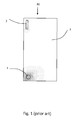
- a prior art antenna device 30 comprising a monopole antenna 2 and a loop antenna 4 being closely spaced and positioned on a supporting structure 3, such a printed circuit board.
- a supporting structure 3 such a printed circuit board.
- the loop antenna 4 is actively excited and the radiation pattern is shown with dots. The closer the dots are placed, the higher is the power of the radiated field. It is clearly seen that even though only the loop antenna is actively excited, an electromagnetic field is also formed around the monopole antenna 2.
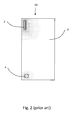
- a same prior art antenna device 30 is shown comprising a monopole antenna 2 and a loop antenna 4.
- only the monopole antenna 2 is actively excited, and the radiation pattern is shown with dots. The closer the dots are placed, the higher is the power of the radiated field. It is clearly seen that even though only the monopole antenna 2 is actively excited, an electromagnetic field is also formed around the loop antenna 4.
- Fig. 3 shows an antenna device 1 according to the present invention comprising a first antenna 2, a second antenna, 4 and a parasitic antenna element 5.
- the first antenna 2, the second antenna, 4 and the parasitic antenna element 5 are positioned on a supporting substrate 3.
- the first antenna 2 is shown as monopole antenna and the second antenna 4 is shown as a loop antenna.
- the first antenna and the second antenna may be any antenna elements, including but not limited to patch antennas, monopole antennas, such as pifa antennas, dipole antennas, etc.
- the first antenna is configured to operate within a first frequency band
- the second antenna is configured to operate within a second frequency band.
- At least one of the first and second antennas has a carrier frequency around 2.4 GHz, but the carrier frequency, or main operating frequency, may be selected in the entire frequency band.
- the first antenna and the second antenna are separated by a distance 17 (centre-to-centre).
- the first antenna and the second antenna may be positioned within a distance 17 of a full wavelength of a main operating frequency for at least one of the antennas, such as within a distance of a half wavelength. In the present example, the distance is approximately 62.5 mm.
- the first antenna 2 and the second antenna 4 may provided along a same axis, such as along a first edge 18 of the supporting substrate 3, or they may be provided at an angle to each other different from 0° or 180°, such as at an angle of between 0° and 45°, such as between 180° ⁇ 45°, or any multiple thereof.
- the angle is substantially 0° or substantially 180°.
- the polarisation of the first antenna 2 and the second antenna 4 may be substantially the same, or the angle between the polarisation of the first antenna polarisation and the second antenna polarisation may be between 0° and ⁇ 45°.
- the at least one parasitic element 5 may be provided substantially orthogonally to the first and/or second antenna 2, 4 so as to substantially isolate between the first antenna 2 and the second antenna 4.
- the parasitic antenna element 5 may be any parasitic antenna element, preferably such as a longitudinal parasitic antenna element, and even more preferred such as a ⁇ /4 parasitic antenna element.
- Fig. 3 it is seen that the parasitic antenna element 5 is positioned substantially along a second edge 19 of the rectangular supporting substrate 3.
- the second edge 19 is seen to be substantially orthogonal to the first edge 18.
- the supporting substrate 3 may have any other shape, such as a parallelogram, a trapezoid or any other shape suitable for forming a ground plane for one or more of the antennas 2, 4 or parasitic antenna element(s) 5.
- the antennas and the parasitic antenna element(s) are preferably positioned adjacent an edge of the supporting substrate.
- the antennas and the parasitic antenna elements may be positioned anywhere, such as anywhere on the supporting substrate.
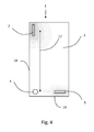
- Fig. 4 the same antenna device as shown in Fig.3 is shown, however, in Fig. 4 only the first antenna 2 is actively excited. It is seen that an electromagnetic field is induced around the first antenna 2, and additionally at the parasitic antenna element 5, whereas only a weak coupling to the second antenna 4 is seen.
- Fig. 5 shows an antenna device wherein the main current directions upon excitation are shown.
- the first antenna 2 and the second antenna 4 are configured so that when the first antenna and the second antenna are excited, the at least one parasitic element 5 is configured to draw electromagnetically induced current in the supporting structure 3 between the first antenna 2 and the at least one parasitic antenna element 5 in a first direction 6 and configured to draw electromagnetically induced current in the supporting structure 3 between the second antenna 4 and the parasitic antenna element 5 in a second direction 7, the first and second directions being substantially orthogonal.
- the parasitic antenna element 5 being positioned substantially orthogonal to at least the first antenna 2 draws a current in a direction from the first antenna 2 towards the parasitic antenna element 5.
- the parasitic antenna element furthermore draws a current from the second antenna element 4, in a direction 7 being substantially orthogonal to the first direction 6.
- FIG. 6 an approximate current distribution for current induced in the supporting structure 3 upon excitation of the first antenna 2 and the second antenna 4, in and around the first antenna 2, the second antenna 4 and the parasitic antenna element 5 is shown schematically, and it is seen that the main current components run along the directions 6 and 7 as shown in Fig. 5 .
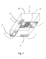
- Fig. 7 shows another antenna device 1, wherein each antenna element 2, 4, 5 has a separate supporting substrate 3. It is envisaged that the first antenna 2, the second antenna 4 and the parasitic antenna element 5 may be positioned at different supporting structures 3, 3', 3", 3"', and may be provided detachable to each other.
- the supporting substrates 3, 3', 3", 3'" may preferably have a common ground potential, however, the supporting substrates 3, 3', 3", 3"' may have different relative ground potentials.
- the antenna device 1 may further comprise a first electrical circuit structured to be electrically coupled to the first antenna 2, and a second electrical circuit structured to be electrically coupled to the second antenna 4, wherein the first and second electrical circuits are structured to be electrically connected so that information received by the second antenna 4 is provided to the second electrical circuit and transferred to the first electrical circuit for transmission via the first antenna 2.
- the information received by the second electrical circuit may be transmitted to the first electrical circuit via a central processing unit 10, and vice versa.
- Fig. 7 only the conductors to and from the CPU 10 are shown.
- the central processing unit 10 may transform or adapt the information received via the second antenna protocol to a format being transmittable via the first antenna protocol and vice versa. Furthermore, the central processing unit 10 may transmit and receive further signals, such as signals for controlling the communication.
- the antenna device 1 in Fig. 7 is accommodated within a housing 20.
- Fig. 8 shows the isolation between the first antenna 2 and the second antenna 4 as a function of frequency with and without a parasitic antenna element 5 present.
- the first antenna and the second antenna are configured for radiation of an electromagnetic field of approximately 2.4 GHz, and the parasitic antenna element 5 is tuned so as to obtain a low coupling efficiency, i.e. a good isolation at 2.4 GHz.
- the curve 12 shows the isolation as a function of frequency in an antenna device wherein there is no parasitic antenna element present, and no improved isolation is seen around 2.4 GHz.
- the curve 11 shows the isolation as a function of frequency in an antenna device 1 wherein a parasitic antenna element 5 is present, and preferably positioned substantially orthogonally to the first 2 and/or second 4 antenna so as to substantially isolate between the first antenna 2 and the second antenna 4.
- the isolation is significantly improved around 2.4 GHz, thus a low coupling between the first and second antennas is achieved.
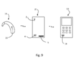
- a coupling device 21 according to an embodiment of the present invention is shown.
- the coupling device 21 provides for coupling between a communication device 13, such as a mobile phone, and a hearing aid 15.
- the coupling device 21 comprises a first antenna 2 configured to communicate with the hearing aid 15, a second antenna 4 configured to communicate with the communication device 13, and at least one parasitic antenna element 5.
- the at least one parasitic element is provided substantially orthogonally to the first and/or second antenna so as to substantially isolate between the first antenna and the second antenna.
Landscapes
- Engineering & Computer Science (AREA)
- Computer Networks & Wireless Communication (AREA)
- Support Of Aerials (AREA)
- Variable-Direction Aerials And Aerial Arrays (AREA)
- Details Of Aerials (AREA)
- Transceivers (AREA)
Priority Applications (10)
| Application Number | Priority Date | Filing Date | Title |
|---|---|---|---|
| EP11174155A EP2546926A1 (fr) | 2011-07-15 | 2011-07-15 | Dispositif d'antenne |
| US13/229,634 US10601128B2 (en) | 2011-07-15 | 2011-09-09 | Device and method using a parasitic antenna element to substantially isolate or decouple first and second antennas respectively operating in first and second frequency bands |
| PCT/EP2011/067755 WO2012059302A2 (fr) | 2010-10-12 | 2011-10-12 | Dispositif d'antenne |
| US13/878,642 US10205227B2 (en) | 2010-10-12 | 2011-10-12 | Antenna device |
| JP2013533192A JP2013541913A (ja) | 2010-10-12 | 2011-10-12 | アンテナ装置 |
| CN201180049547.5A CN103329350B (zh) | 2010-10-12 | 2011-10-12 | 天线装置 |
| DK11772919.4T DK2628210T3 (en) | 2010-10-12 | 2011-10-12 | Hearing aid comprising an antenna device |
| EP11772919.4A EP2628210B1 (fr) | 2010-10-12 | 2011-10-12 | Prothese auditive comprenant un dispositif d'antenne |
| JP2012153679A JP5546587B2 (ja) | 2011-07-15 | 2012-07-09 | アンテナデバイス |
| CN201210246620.4A CN102983399B (zh) | 2011-07-15 | 2012-07-16 | 天线设备 |
Applications Claiming Priority (1)
| Application Number | Priority Date | Filing Date | Title |
|---|---|---|---|
| EP11174155A EP2546926A1 (fr) | 2011-07-15 | 2011-07-15 | Dispositif d'antenne |
Publications (1)
| Publication Number | Publication Date |
|---|---|
| EP2546926A1 true EP2546926A1 (fr) | 2013-01-16 |
Family
ID=44582226
Family Applications (1)
| Application Number | Title | Priority Date | Filing Date |
|---|---|---|---|
| EP11174155A Withdrawn EP2546926A1 (fr) | 2010-10-12 | 2011-07-15 | Dispositif d'antenne |
Country Status (4)
| Country | Link |
|---|---|
| US (1) | US10601128B2 (fr) |
| EP (1) | EP2546926A1 (fr) |
| JP (1) | JP5546587B2 (fr) |
| CN (1) | CN102983399B (fr) |
Cited By (5)
| Publication number | Priority date | Publication date | Assignee | Title |
|---|---|---|---|---|
| DE102013217821A1 (de) | 2013-09-06 | 2015-03-12 | Robert Bosch Gmbh | Elektrische Maschine und Verfahren zur Herstellung einer elektrischen Maschine |
| US9661426B2 (en) | 2015-06-22 | 2017-05-23 | Gn Hearing A/S | Hearing aid having combined antennas |
| US10051388B2 (en) | 2016-09-21 | 2018-08-14 | Starkey Laboratories, Inc. | Radio frequency antenna for an in-the-ear hearing device |
| US11323833B2 (en) | 2016-10-27 | 2022-05-03 | Starkey Laboratories, Inc. | Antenna structure for hearing devices |
| EP3506656B1 (fr) | 2017-12-29 | 2023-02-22 | GN Hearing A/S | Appareil auditif comprenant un élément d'antenne de batterie parasite |
Families Citing this family (25)
| Publication number | Priority date | Publication date | Assignee | Title |
|---|---|---|---|---|
| US9774961B2 (en) | 2005-06-05 | 2017-09-26 | Starkey Laboratories, Inc. | Hearing assistance device ear-to-ear communication using an intermediate device |
| US8041066B2 (en) | 2007-01-03 | 2011-10-18 | Starkey Laboratories, Inc. | Wireless system for hearing communication devices providing wireless stereo reception modes |
| US8208642B2 (en) | 2006-07-10 | 2012-06-26 | Starkey Laboratories, Inc. | Method and apparatus for a binaural hearing assistance system using monaural audio signals |
| US9420385B2 (en) | 2009-12-21 | 2016-08-16 | Starkey Laboratories, Inc. | Low power intermittent messaging for hearing assistance devices |
| US9118354B2 (en) * | 2011-08-30 | 2015-08-25 | Apple Inc. | Electronic device with shared near field communications element |
| US9374650B2 (en) | 2012-07-17 | 2016-06-21 | Starkey Laboratories, Inc. | System and method for embedding conductive traces into hearing assistance device housings |
| EP2932560B2 (fr) | 2012-12-12 | 2020-09-23 | Sivantos Pte. Ltd. | Dipôle replié pour prothèse auditive |
| US9437935B2 (en) * | 2013-02-27 | 2016-09-06 | Microsoft Technology Licensing, Llc | Dual band antenna pair with high isolation |
| CN104577314A (zh) * | 2013-10-23 | 2015-04-29 | 中兴通讯股份有限公司 | 一种提高pcb板抗干扰方法和抗干扰pcb板及其终端 |
| TWI481117B (zh) * | 2013-12-23 | 2015-04-11 | Wistron Neweb Corp | 天線系統 |
| US10003379B2 (en) | 2014-05-06 | 2018-06-19 | Starkey Laboratories, Inc. | Wireless communication with probing bandwidth |
| US9774078B2 (en) * | 2014-09-19 | 2017-09-26 | Innowave IP Inc. | Antenna ground plane extension or antenna extension on lanyard |
| US10109918B2 (en) | 2016-01-22 | 2018-10-23 | Airgain Incorporated | Multi-element antenna for multiple bands of operation and method therefor |
| US10510199B2 (en) | 2017-08-07 | 2019-12-17 | Milwaukee Electric Tool Corporation | Power tool with irreversably lockable compartment |
| JP2019121925A (ja) | 2018-01-05 | 2019-07-22 | 富士通株式会社 | アンテナ装置、及び、無線通信装置 |
| WO2019168974A1 (fr) * | 2018-02-27 | 2019-09-06 | Commscope Technologies Llc | Module d'antenne mimo et unité d'antenne mimo pour système d'antenne distribué |
| CN110708080B (zh) * | 2018-07-10 | 2021-12-14 | 南京矽力微电子技术有限公司 | 通信装置 |
| CN109616745B (zh) * | 2018-12-05 | 2021-10-26 | 歌尔股份有限公司 | 天线结构和电子设备 |
| JP6679120B1 (ja) * | 2019-02-01 | 2020-04-15 | Necプラットフォームズ株式会社 | 無線通信装置およびアンテナ構成方法 |
| US11665519B2 (en) | 2019-02-06 | 2023-05-30 | Milwaukee Electric Tool Corporation | Power tool with shared terminal block |
| KR102524568B1 (ko) * | 2019-03-21 | 2023-04-21 | 교세라 에이브이엑스 컴포넌츠(샌디에고)인코포레이티드 | 다중 모드 안테나 시스템 |
| US10916841B2 (en) * | 2019-06-28 | 2021-02-09 | Nvidia Corporation | Techniques to increase antenna-to-antenna isolation suitable for enhanced MIMO performance |
| KR20220122631A (ko) * | 2019-11-21 | 2022-09-02 | 밀워키 일렉트릭 툴 코포레이션 | 전동 공구를 위한 삽입식 무선 통신 장치 |
| JP2024025115A (ja) * | 2022-08-10 | 2024-02-26 | パナソニックIpマネジメント株式会社 | 通信ユニット、通信装置、機器、照明器具、及び通信システム |
| US12603428B2 (en) * | 2024-05-29 | 2026-04-14 | Dell Products L.P. | Information handling system dongle with orthogonal radiating antenna planes |
Citations (6)
| Publication number | Priority date | Publication date | Assignee | Title |
|---|---|---|---|---|
| US20050057414A1 (en) * | 2001-04-11 | 2005-03-17 | Gregory Poilasne | Reconfigurable radiation desensitivity bracket systems and methods |
| US20050128162A1 (en) * | 2003-12-10 | 2005-06-16 | Matsushita Electric Industrail Co., Ltd. | Antenna |
| WO2006018711A1 (fr) * | 2004-08-20 | 2006-02-23 | Nokia Corporation | Amelioration de l'isolation d'antennes a l'aide d'elements hyperfrequences mis a la terre |
| US20090243944A1 (en) * | 2008-03-25 | 2009-10-01 | Jung Kang-Jae | Portable terminal |
| EP2193767A1 (fr) * | 2008-12-02 | 2010-06-09 | Oticon A/S | Dispositif pour le traitement du bégaiement |
| WO2010065356A1 (fr) * | 2008-11-25 | 2010-06-10 | Molex Incorporated | Combiné mobile compatible avec une assistance à l'écoute |
Family Cites Families (23)
| Publication number | Priority date | Publication date | Assignee | Title |
|---|---|---|---|---|
| US6426723B1 (en) * | 2001-01-19 | 2002-07-30 | Nortel Networks Limited | Antenna arrangement for multiple input multiple output communications systems |
| WO2002078123A1 (fr) * | 2001-03-23 | 2002-10-03 | Telefonaktiebolaget L M Ericsson (Publ) | Systeme multi-bande, multi-antenne integre |
| ATE382194T1 (de) * | 2002-06-21 | 2008-01-15 | Research In Motion Ltd | Mehrelementantenne mit parasitärem koppler |
| JP2004040361A (ja) * | 2002-07-02 | 2004-02-05 | Ntt Docomo Inc | ビーム幅可変アンテナ装置 |
| WO2004077610A1 (fr) * | 2003-02-28 | 2004-09-10 | Research In Motion Limited | Antenne a plusieurs elements dotee d'un element d'antenne a bande large |
| US7525502B2 (en) * | 2004-08-20 | 2009-04-28 | Nokia Corporation | Isolation between antennas using floating parasitic elements |
| JP2006229528A (ja) * | 2005-02-17 | 2006-08-31 | Matsushita Electric Ind Co Ltd | アンテナ装置およびそれを用いた携帯無線機 |
| EP2227042B1 (fr) * | 2005-05-03 | 2011-12-28 | Oticon A/S | Système et procédé pour partager des ressources réseau entre des prothèses auditives |
| KR100859864B1 (ko) * | 2005-06-13 | 2008-09-24 | 삼성전자주식회사 | 아이솔레이션 소자를 포함하는 평판형 미모 어레이 안테나 |
| KR100699472B1 (ko) * | 2005-09-27 | 2007-03-26 | 삼성전자주식회사 | 아이솔레이션 소자를 포함하는 평판형 미모 어레이 안테나 |
| DE602006016645D1 (de) | 2005-12-19 | 2010-10-14 | Nxp Bv | Funkempfänger, funksender und hörgerät |
| JP4667310B2 (ja) | 2006-07-04 | 2011-04-13 | 株式会社エヌ・ティ・ティ・ドコモ | 無給電素子を備えたマルチアンテナ |
| JP2008172672A (ja) * | 2007-01-15 | 2008-07-24 | Matsushita Electric Ind Co Ltd | アンテナ |
| KR100895448B1 (ko) * | 2007-07-03 | 2009-05-07 | 삼성전자주식회사 | 소형화된 mimo 안테나 |
| JP4966125B2 (ja) * | 2007-07-27 | 2012-07-04 | 株式会社東芝 | アンテナ装置及び無線機 |
| US7916089B2 (en) * | 2008-01-04 | 2011-03-29 | Apple Inc. | Antenna isolation for portable electronic devices |
| US8014821B2 (en) * | 2008-01-18 | 2011-09-06 | Research In Motion Limited | Mobile wireless communications device including shared voice coil to provide hearing aid compatibility and related methods |
| US7724201B2 (en) * | 2008-02-15 | 2010-05-25 | Sierra Wireless, Inc. | Compact diversity antenna system |
| US7924225B2 (en) * | 2008-06-23 | 2011-04-12 | Hong Kong Applied Science And Technology Research Institute Co., Ltd. | Direction finding antenna systems and methods for use thereof |
| KR101013388B1 (ko) | 2009-02-27 | 2011-02-14 | 주식회사 모비텍 | 기생소자를 갖는 mimo 안테나 |
| JP2011066713A (ja) * | 2009-09-17 | 2011-03-31 | Furukawa Electric Co Ltd:The | 統合アンテナ |
| US8730110B2 (en) * | 2010-03-05 | 2014-05-20 | Blackberry Limited | Low frequency diversity antenna system |
| US8483415B2 (en) * | 2010-06-18 | 2013-07-09 | Motorola Mobility Llc | Antenna system with parasitic element for hearing aid compliant electromagnetic emission |
-
2011
- 2011-07-15 EP EP11174155A patent/EP2546926A1/fr not_active Withdrawn
- 2011-09-09 US US13/229,634 patent/US10601128B2/en active Active
-
2012
- 2012-07-09 JP JP2012153679A patent/JP5546587B2/ja not_active Expired - Fee Related
- 2012-07-16 CN CN201210246620.4A patent/CN102983399B/zh not_active Expired - Fee Related
Patent Citations (6)
| Publication number | Priority date | Publication date | Assignee | Title |
|---|---|---|---|---|
| US20050057414A1 (en) * | 2001-04-11 | 2005-03-17 | Gregory Poilasne | Reconfigurable radiation desensitivity bracket systems and methods |
| US20050128162A1 (en) * | 2003-12-10 | 2005-06-16 | Matsushita Electric Industrail Co., Ltd. | Antenna |
| WO2006018711A1 (fr) * | 2004-08-20 | 2006-02-23 | Nokia Corporation | Amelioration de l'isolation d'antennes a l'aide d'elements hyperfrequences mis a la terre |
| US20090243944A1 (en) * | 2008-03-25 | 2009-10-01 | Jung Kang-Jae | Portable terminal |
| WO2010065356A1 (fr) * | 2008-11-25 | 2010-06-10 | Molex Incorporated | Combiné mobile compatible avec une assistance à l'écoute |
| EP2193767A1 (fr) * | 2008-12-02 | 2010-06-09 | Oticon A/S | Dispositif pour le traitement du bégaiement |
Cited By (11)
| Publication number | Priority date | Publication date | Assignee | Title |
|---|---|---|---|---|
| DE102013217821A1 (de) | 2013-09-06 | 2015-03-12 | Robert Bosch Gmbh | Elektrische Maschine und Verfahren zur Herstellung einer elektrischen Maschine |
| US9661426B2 (en) | 2015-06-22 | 2017-05-23 | Gn Hearing A/S | Hearing aid having combined antennas |
| US11172315B2 (en) | 2015-06-22 | 2021-11-09 | Gn Hearing A/S | Hearing aid having combined antennas |
| US10051388B2 (en) | 2016-09-21 | 2018-08-14 | Starkey Laboratories, Inc. | Radio frequency antenna for an in-the-ear hearing device |
| US10687156B2 (en) | 2016-09-21 | 2020-06-16 | Starkey Laboratories, Inc. | Radio frequency antenna for an in-the-ear hearing device |
| US11470430B2 (en) | 2016-09-21 | 2022-10-11 | Starkey Laboratories, Inc. | Radio frequency antenna for an in-the-ear hearing device |
| US12022263B2 (en) | 2016-09-21 | 2024-06-25 | Starkey Laboratories, Inc. | Radio frequency antenna for an in-the-ear hearing device |
| US11323833B2 (en) | 2016-10-27 | 2022-05-03 | Starkey Laboratories, Inc. | Antenna structure for hearing devices |
| US11601767B2 (en) | 2016-10-27 | 2023-03-07 | Starkey Laboratories, Inc. | Antenna structure for hearing devices |
| US11950059B2 (en) | 2016-10-27 | 2024-04-02 | Starkey Laboratories, Inc. | Antenna structure for hearing devices |
| EP3506656B1 (fr) | 2017-12-29 | 2023-02-22 | GN Hearing A/S | Appareil auditif comprenant un élément d'antenne de batterie parasite |
Also Published As
| Publication number | Publication date |
|---|---|
| CN102983399A (zh) | 2013-03-20 |
| US10601128B2 (en) | 2020-03-24 |
| JP5546587B2 (ja) | 2014-07-09 |
| US20130017786A1 (en) | 2013-01-17 |
| JP2013042483A (ja) | 2013-02-28 |
| CN102983399B (zh) | 2016-08-10 |
Similar Documents
| Publication | Publication Date | Title |
|---|---|---|
| US10601128B2 (en) | Device and method using a parasitic antenna element to substantially isolate or decouple first and second antennas respectively operating in first and second frequency bands | |
| EP2996196B1 (fr) | Système multi-antenne et terminal mobile | |
| CA2554152C (fr) | Systeme d'antenne multibande | |
| KR101547746B1 (ko) | 섀시 여기 안테나 컴포넌트, 안테나 장치 및 이에 대한 모바일 통신 디바이스 | |
| KR100467569B1 (ko) | 송수신일체형마이크로스트립패치안테나 | |
| JP3864127B2 (ja) | デュアルフィーディングポートを有するマルチバンドチップアンテナ及びこれを用いる移動通信装置 | |
| US7952529B2 (en) | Dual band antenna | |
| US6909401B2 (en) | Antenna device | |
| KR101257615B1 (ko) | 휴대형 통신 디바이스를 위한 낮은 프로파일의 접힘형 안테나 어셈블리 | |
| US9077077B2 (en) | Mobile communication device and antenna device | |
| TWI403021B (zh) | 載具和裝置 | |
| EP2381529B1 (fr) | Structures de communication incluant des antennes avec des branches d'antennes séparées couplées pour alimenter et mettre à la terre des conducteurs | |
| JPWO2004109857A1 (ja) | アンテナとそれを用いた電子機器 | |
| EP2256859A1 (fr) | Arrangement d'antennes, procédé de réglage d'un arrangement d'antennes et appareil avec arrangement d'antennes | |
| WO2022179324A1 (fr) | Unité d'antenne, boîtier et dispositif électronique | |
| CN105609969A (zh) | 通信终端 | |
| KR20050054478A (ko) | 유전체 안테나 및 그것을 포함하는 통신 장치 | |
| US20110128193A1 (en) | Card device for wireless communication | |
| CN103460506B (zh) | 具有圆极化特性的双天线结构 | |
| CN205509020U (zh) | 通信终端 | |
| CN209312988U (zh) | 多频带wlan天线设备和调制解调器 | |
| CN103155275A (zh) | 天线装置和方法 | |
| KR20160119501A (ko) | 다중밴드 안테나 | |
| KR101218718B1 (ko) | 안테나 장치 및 이동통신 단말기 | |
| US20080094303A1 (en) | Planer inverted-F antenna device |
Legal Events
| Date | Code | Title | Description |
|---|---|---|---|
| PUAI | Public reference made under article 153(3) epc to a published international application that has entered the european phase |
Free format text: ORIGINAL CODE: 0009012 |
|
| AK | Designated contracting states |
Kind code of ref document: A1 Designated state(s): AL AT BE BG CH CY CZ DE DK EE ES FI FR GB GR HR HU IE IS IT LI LT LU LV MC MK MT NL NO PL PT RO RS SE SI SK SM TR |
|
| AX | Request for extension of the european patent |
Extension state: BA ME |
|
| 17P | Request for examination filed |
Effective date: 20130716 |
|
| RBV | Designated contracting states (corrected) |
Designated state(s): AL AT BE BG CH CY CZ DE DK EE ES FI FR GB GR HR HU IE IS IT LI LT LU LV MC MK MT NL NO PL PT RO RS SE SI SK SM TR |
|
| STAA | Information on the status of an ep patent application or granted ep patent |
Free format text: STATUS: THE APPLICATION IS DEEMED TO BE WITHDRAWN |
|
| 18D | Application deemed to be withdrawn |
Effective date: 20170201 |