EP2546980A2 - Elektromotorsteuerungssystem - Google Patents
Elektromotorsteuerungssystem Download PDFInfo
- Publication number
- EP2546980A2 EP2546980A2 EP12187918A EP12187918A EP2546980A2 EP 2546980 A2 EP2546980 A2 EP 2546980A2 EP 12187918 A EP12187918 A EP 12187918A EP 12187918 A EP12187918 A EP 12187918A EP 2546980 A2 EP2546980 A2 EP 2546980A2
- Authority
- EP
- European Patent Office
- Prior art keywords
- inverter
- phase
- short
- electric motor
- switching elements
- Prior art date
- Legal status (The legal status is an assumption and is not a legal conclusion. Google has not performed a legal analysis and makes no representation as to the accuracy of the status listed.)
- Granted
Links
- 238000001514 detection method Methods 0.000 claims abstract description 31
- 238000010992 reflux Methods 0.000 claims abstract description 14
- 238000002485 combustion reaction Methods 0.000 description 25
- 238000010586 diagram Methods 0.000 description 12
- 239000000470 constituent Substances 0.000 description 7
- 239000003990 capacitor Substances 0.000 description 5
- 238000009499 grossing Methods 0.000 description 5
- 230000005540 biological transmission Effects 0.000 description 3
- 230000007257 malfunction Effects 0.000 description 2
- 241000209527 Arum Species 0.000 description 1
- 235000006481 Colocasia esculenta Nutrition 0.000 description 1
Images


Classifications
-
- H—ELECTRICITY
- H02—GENERATION; CONVERSION OR DISTRIBUTION OF ELECTRIC POWER
- H02P—CONTROL OR REGULATION OF ELECTRIC MOTORS, ELECTRIC GENERATORS OR DYNAMO-ELECTRIC CONVERTERS; CONTROLLING TRANSFORMERS, REACTORS OR CHOKE COILS
- H02P27/00—Arrangements or methods for the control of AC motors characterised by the kind of supply voltage
- H02P27/04—Arrangements or methods for the control of AC motors characterised by the kind of supply voltage using variable-frequency supply voltage, e.g. inverter or converter supply voltage
- H02P27/06—Arrangements or methods for the control of AC motors characterised by the kind of supply voltage using variable-frequency supply voltage, e.g. inverter or converter supply voltage using DC to AC converters or inverters
-
- B—PERFORMING OPERATIONS; TRANSPORTING
- B60—VEHICLES IN GENERAL
- B60L—PROPULSION OF ELECTRICALLY-PROPELLED VEHICLES; SUPPLYING ELECTRIC POWER FOR AUXILIARY EQUIPMENT OF ELECTRICALLY-PROPELLED VEHICLES; ELECTRODYNAMIC BRAKE SYSTEMS FOR VEHICLES IN GENERAL; MAGNETIC SUSPENSION OR LEVITATION FOR VEHICLES; MONITORING OPERATING VARIABLES OF ELECTRICALLY-PROPELLED VEHICLES; ELECTRIC SAFETY DEVICES FOR ELECTRICALLY-PROPELLED VEHICLES
- B60L3/00—Electric devices on electrically-propelled vehicles for safety purposes; Monitoring operating variables, e.g. speed, deceleration or energy consumption
- B60L3/0023—Detecting, eliminating, remedying or compensating for drive train abnormalities, e.g. failures within the drive train
- B60L3/003—Detecting, eliminating, remedying or compensating for drive train abnormalities, e.g. failures within the drive train relating to inverters
-
- B—PERFORMING OPERATIONS; TRANSPORTING
- B60—VEHICLES IN GENERAL
- B60L—PROPULSION OF ELECTRICALLY-PROPELLED VEHICLES; SUPPLYING ELECTRIC POWER FOR AUXILIARY EQUIPMENT OF ELECTRICALLY-PROPELLED VEHICLES; ELECTRODYNAMIC BRAKE SYSTEMS FOR VEHICLES IN GENERAL; MAGNETIC SUSPENSION OR LEVITATION FOR VEHICLES; MONITORING OPERATING VARIABLES OF ELECTRICALLY-PROPELLED VEHICLES; ELECTRIC SAFETY DEVICES FOR ELECTRICALLY-PROPELLED VEHICLES
- B60L50/00—Electric propulsion with power supplied within the vehicle
- B60L50/10—Electric propulsion with power supplied within the vehicle using propulsion power supplied by engine-driven generators, e.g. generators driven by combustion engines
- B60L50/16—Electric propulsion with power supplied within the vehicle using propulsion power supplied by engine-driven generators, e.g. generators driven by combustion engines with provision for separate direct mechanical propulsion
-
- H—ELECTRICITY
- H02—GENERATION; CONVERSION OR DISTRIBUTION OF ELECTRIC POWER
- H02P—CONTROL OR REGULATION OF ELECTRIC MOTORS, ELECTRIC GENERATORS OR DYNAMO-ELECTRIC CONVERTERS; CONTROLLING TRANSFORMERS, REACTORS OR CHOKE COILS
- H02P29/00—Arrangements for regulating or controlling electric motors, appropriate for both AC and DC motors
- H02P29/02—Providing protection against overload without automatic interruption of supply
- H02P29/024—Detecting a fault condition, e.g. short circuit, locked rotor, open circuit or loss of load
- H02P29/0241—Detecting a fault condition, e.g. short circuit, locked rotor, open circuit or loss of load the fault being an overvoltage
-
- H—ELECTRICITY
- H02—GENERATION; CONVERSION OR DISTRIBUTION OF ELECTRIC POWER
- H02M—APPARATUS FOR CONVERSION BETWEEN AC AND AC, BETWEEN AC AND DC, OR BETWEEN DC AND DC, AND FOR USE WITH MAINS OR SIMILAR POWER SUPPLY SYSTEMS; CONVERSION OF DC OR AC INPUT POWER INTO SURGE OUTPUT POWER; CONTROL OR REGULATION THEREOF
- H02M1/00—Details of apparatus for conversion
- H02M1/0003—Details of control, feedback or regulation circuits
- H02M1/0009—Devices or circuits for detecting current in a converter
-
- Y—GENERAL TAGGING OF NEW TECHNOLOGICAL DEVELOPMENTS; GENERAL TAGGING OF CROSS-SECTIONAL TECHNOLOGIES SPANNING OVER SEVERAL SECTIONS OF THE IPC; TECHNICAL SUBJECTS COVERED BY FORMER USPC CROSS-REFERENCE ART COLLECTIONS [XRACs] AND DIGESTS
- Y02—TECHNOLOGIES OR APPLICATIONS FOR MITIGATION OR ADAPTATION AGAINST CLIMATE CHANGE
- Y02T—CLIMATE CHANGE MITIGATION TECHNOLOGIES RELATED TO TRANSPORTATION
- Y02T10/00—Road transport of goods or passengers
- Y02T10/60—Other road transportation technologies with climate change mitigation effect
- Y02T10/64—Electric machine technologies in electromobility
-
- Y—GENERAL TAGGING OF NEW TECHNOLOGICAL DEVELOPMENTS; GENERAL TAGGING OF CROSS-SECTIONAL TECHNOLOGIES SPANNING OVER SEVERAL SECTIONS OF THE IPC; TECHNICAL SUBJECTS COVERED BY FORMER USPC CROSS-REFERENCE ART COLLECTIONS [XRACs] AND DIGESTS
- Y02—TECHNOLOGIES OR APPLICATIONS FOR MITIGATION OR ADAPTATION AGAINST CLIMATE CHANGE
- Y02T—CLIMATE CHANGE MITIGATION TECHNOLOGIES RELATED TO TRANSPORTATION
- Y02T10/00—Road transport of goods or passengers
- Y02T10/60—Other road transportation technologies with climate change mitigation effect
- Y02T10/70—Energy storage systems for electromobility, e.g. batteries
-
- Y—GENERAL TAGGING OF NEW TECHNOLOGICAL DEVELOPMENTS; GENERAL TAGGING OF CROSS-SECTIONAL TECHNOLOGIES SPANNING OVER SEVERAL SECTIONS OF THE IPC; TECHNICAL SUBJECTS COVERED BY FORMER USPC CROSS-REFERENCE ART COLLECTIONS [XRACs] AND DIGESTS
- Y02—TECHNOLOGIES OR APPLICATIONS FOR MITIGATION OR ADAPTATION AGAINST CLIMATE CHANGE
- Y02T—CLIMATE CHANGE MITIGATION TECHNOLOGIES RELATED TO TRANSPORTATION
- Y02T10/00—Road transport of goods or passengers
- Y02T10/60—Other road transportation technologies with climate change mitigation effect
- Y02T10/7072—Electromobility specific charging systems or methods for batteries, ultracapacitors, supercapacitors or double-layer capacitors
Definitions
- the present invention relates to a control system for an electric motor to which electric power is supplied from a DC power supply via a multi-phase inverter in which a switch unit including a switching element and a reflux diode connected in parallel to the switching element is provided on each of a positive side and a negative side of each of arms of respective phases.
- FIG. 14 is a block diagram of an internal configuration of the HEV.
- driving force from an internal combustion engine (ENG) 107 and/or an electric motor (MOT) 101 is transmitted to drive wheels 153 via a gearbox 109 and a drive shaft 151.
- a rotor of the electric motor 101 is connected directly to a drive shaft of the internal combustion engine 107.
- the rotor of the electric motor 101 also rotates.
- the internal combustion engine 107 generates a driving force (an output torque) to run the vehicle.
- An engine ECU (ENG ECU) 117 controls the internal combustion engine 107.
- the electric motor 101 is a three-phase AC motor, for example, and generates a driving force (an output torque) to run the vehicle.
- a motor ECU (MOT ECU) 119 controls the electric motor 101.
- a battery (BATT) 103 is a DC power supply and supplies electric power to the electric motor 101 via an inverter 105.
- the output voltage of the battery 103 is a high voltage (for example, 100 to 200V).
- the inverter 105 converts a DC current from the battery 103 into three phase AC currents.
- An inverter ECU (INV ECU) 111 controls the inverter 105.
- a clutch 113 interrupts or connects a transmission line of driving force from the internal engine 107 and/or the electric motor 101 to the drive wheels 153 based on an instruction from a management ECU 115.
- the clutch 113 is disengaged, the driving force is not transmitted to the drive wheels 153, but the clutch 113 is engaged, the drive force is transmitted to the drive wheel 153.
- the gearbox 109 is a transmission which converts the driving force from the internal combustion engine 107 and/or the electric motor 101 into a rotational speed and torque at desirable gear ratios for transmission to the drive shaft 151.
- the management ECU (MG ECU) 115 controls the internal combustion engine 107, the electric motor 101 and the inverter 105, instructs the clutch 113 to be engaged or disengaged and instructs the gearbox 109 to change the gear ratios thereof.
- Fig. 15 is a block diagram of a driving system installed in the vehicle shown in Fig. 14 for driving the electric motor 101.
- arms 1u, 1v, 1w are provided correspondingly with phases (U phase, V phase, W phase) of the electric motor 101, and the arms 1u, 1v, 1w are connected in parallel to a smoothing capacitor C between power supply terminals 2a, 2b.
- Central points of the respective arms 1u, 1v, 1w are connected to a U-phase armature Au, a V-phase armature Av and a W-phase armature Aw of the electric motor 101, respectively.
- a switch unit includes a switching element such as IBGT or MOSFET and a reflux diode connected in parallel to the switching element.
- Such switch unit is provided on each of a positive side and a negative side on each of the respective arums.
- a switch unit 5a including a switching element 3a and a reflux diode 4a is provided on a positive side
- a switch unit 5b including a switching element 3b and a reflux diode 4b is provided on a negative side.
- a collector of the positive-side switching element 3a and a cathode of the positive-side reflux diode 4a are connected to the positive-side power supply terminal 2a, and an emitter of the negative-side switching element 3b and an anode of the negative-side reflux diode 4b are connected to the negative-side power supply terminal 2b.
- a positive terminal of the battery 103 is connected to the positive-side power supply terminal 2a via a contactor SW.
- Each switching element is on/off controlled by a control signal from the inverter ECU 111.
- a gate resistor R is connected to a gate terminal of each switching element, and a control signal from the inverter ECU 111 is inputted into the gate terminal via the gate resistor R.
- Patent Document 1 when the switching element of the switching portion 5b to which a U-phase current flows short-circuits to fail, the inverter ECU 111 on controls the switching elements of the switching portions 5b which are provided on the negative side and off controls the switching elements of the switch units 5a which are provided on the positive side. Consequently, there is produced a state in which inverter 105 side ends of the armatures Au, Av, Aw of the respective phases of the electric motor 101 are substantially short-circuited relative to each other.
- a control to generate the three-phase short-circuited state in the electric motor 101 will be referred to as a "three-phase short-circuiting control.”
- Fig. 16 shows examples of waveforms of the respective phases which are generated when the rotor of the electric motor 101 which is in the three-phase short-circuited state is rotated by driving the internal combustion engine 107.
- Patent Document 1 JP-2008-220045-A
- the inverter ECU 222 PWM controls the inverter 105 so that the two switching elements 3a, 3b of each arm are not put in an ON state (an energized state) simultaneously.
- the switch units 5a, 5b of the arm including the short-circuited switch unit are energized simultaneously.
- the electric motor 101 is in operation, electric power is supplied from the battery 103 and is received by the electric motor 101. Consequently, a great current (a short-circuit current) flows to both the switch units 5a, 5b of the arm including the short-circuited switch unit.
- Patent Document 1 during the operation of the electric motor 101, when the positive-side switch unit 5a and the negative-side switch unit 5b of the arm corresponding to any of the phases of the inverter 105 are energized simultaneously, the short-circuit failure of the inverter 105 is detected.
- the motor ECU 119 may not control the electric motor 101 at all when the vehicle runs only on the driving force from the internal combustion engine 107.
- the inverter ECU 111 off controls all the switching elements and opens the contactor SW provided between the battery 103 and the positive-side power supply terminal 2a.
- both the switch units 5a, 5b of the arm corresponding to any of the phases are not energized simultaneously. Therefore, in this state, the short-circuit failure of the inverter 105 is not detected by the short-circuit detection function possessed by Patent Document 1.
- the inverter ECU 111 When he short-circuit failure is not detected although the inverter 105 is failed due to short-circuit, the inverter ECU 111 does not execute the three-phase short-circuiting control, and therefore, a malfunction or failure is eventually generated in the electric motor 101 or the three-phase wires.
- An object of the invention is to provide a control system for an electric motor which can detect a short-circuit failure of the inverter even when the control of the electric motor is stopped.
- Claim 1 provides a control system for an electric motor (for example, an electric motor 101 in an embodiment) to which electric power is supplied from a DC power supply (for example, a battery 103 in the embodiment) via a multi-phase inverter (for example, an inverters 201, 203 in the embodiment), the multi-phase inverter including switch units (for example, switch units 5a, 5b in the embodiment) respectively provided on a positive side and a negative side of arms corresponding to respective phases (for example, arms 1u, 1v, 1w in the embodiment), each switch unit including a switching element (for example, switching elements 3a, 3b) and a reflux diode (for example, reflux diodes 4a, 4b in the embodiment) connected in parallel thereto, comprising:
- Claim 2 provides the system, based on Claim 1, further comprising:
- Claim 3 provides the system, based on Claim 2, further comprising:
- Claim 4 provides the system, based on Claim 2, further comprising:
- Claim 5 provides a control system for an electric motor (for example, an electric motor 101 in an embodiment) to which electric power is supplied from a DC power supply (for example, a battery 103 in the embodiment) via a three-phase inverter (for example, an inverters 201, 203 in the embodiment), the three-phase inverter including switch units (for example, switch units 5a, 5b in the embodiment) respectively provided on a positive side and a negative side of arms corresponding to respective phases (for example, arms 1u, 1v, 1w in the embodiment), each switch unit including a switching element (for example, switching elements 3a, 3b) and a reflux diode (for example, reflux diodes 4a, 4b in the embodiment) connected in parallel thereto, comprising:
- Claim 6 provides the system, based on Claim 5, wherein the short-circuiting determination unit determines that the short-circuit failure occurs in the inverter when all the DC components of the three phase currents exceed the threshold, and determines not only that the short-circuit failure occurs in the inverter but also that one of the sensors making up the phase current detection unit fails when two of the DC components of the three phase currents exceed the threshold.
- Claim 7 provides the system, based on Claim 5, further comprising:
- Claim 8 provides the system, based on Claim 7, further comprising:
- the short-circuit failure of the inverter can be detected even though the control of the electric motor is stopped.
- the electric motor can be controlled based on three-phase short-circuiting control.
- the electric motor can be controlled based on three-phase short-circuiting control while preventing a great current from flowing to the switch unit which short-circuits and fails.
- the short-circuit failure of the inverter can be detected in an ensured fashion.
- An HEV Hybrid Electrical Vehicle
- An HEV runs on driving force of an internal combustion engine and/or an electric motor.
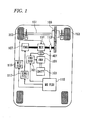
- Fig. 1 is a block diagram showing an internal configuration of an HEV equipped with an electric motor control system according to the invention.
- An HEV (hereinafter, referred to simply as a "vehicle") shown in Fig. 1 includes an electric motor (MOT) 101, a battery (BATT) 103, an inverter (INV) 201, an internal combustion engine (ENG) 107, a management ECU (MG ECU) 115, an engine ECU (ENG ECU) 301, a phase current sensor 401, a clutch 113, a gearbox 109, a drive shaft 151, and drive wheels 153.
- MOT electric motor
- BATT battery
- INV inverter
- ENG internal combustion engine
- MG ECU management ECU
- ENG ECU engine ECU
- the constituent elements other than the inverter 201, the inverter ECU 301 and the phase current sensor 401 are the same as the corresponding constituent elements in the vehicle shown in Fig. 14 .
- Fig. 1 like reference numerals are given to the constituent elements common to those shown in Fig. 14 .
- a driving force from the internal combustion engine 107 and/or the electric motor 101 is transmitted to the drive wheels 153 via the gearbox 109 and the drive shaft 151.
- a rotor of the electric motor 101 is connected directly to a drive shaft of the internal combustion engine 107.
- the rotor of the electric motor 101 also rotates.
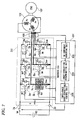
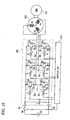
- Fig. 2 is a block diagram showing a system installed in the vehicle for driving the electric motor 101.
- the electric motor 101 is a three-phase AC motor, for example.
- the battery 103 is a DC power supply and supplies electric power to the electric motor 101 via the inverter 201.
- An output voltage of the battery 103 is a high voltage (for example, 100 to 200V).
- the inverter 201 converts a DC current from the battery 103 into three-phase AC currents.
- the inverter 201 has current detection units Seu, Sev, Sew for detecting currents flowing to switching elements 3a and 3b of respective phases.
- the current detection units Seu, Sev, Sew are provided between a negative-side power supply terminal 2b and respective switch units 5b of the phases. Signal indicating currents detected by the current detection units Seu, Sev, Sew are sent to the inverter ECU 301.
- the inverter ECU 301 controls the inverter 201.
- the inverter ECU 301 of this embodiment has a DC component acquiring unit 501, a short-circuiting determination unit 503 and a three-phase short-circuiting control unit 505. Respective operations of these constituent units will be described in detail later.
- the phase current sensor 401 includes three sensors for detecting respective phase currents of the electric motor 101. Signals indicating respective phase currents detected by the phase current sensor 401 are sent to the inverter ECU 301.
- the inverter ECU 301 and the phase current sensor 401 are similar to the corresponding constituent elements shown Fig. 15 . Consequently, also in Fig. 2 , like reference numerals are given to the constituent elements which are like to those shown in Fig. 15 .
- the control of the inverter 201 by the inverter ECU 301 of this embodiment will be described by reference to Fig. 2 .
- the inverter ECU 301 PWM controls the inverter 201 so that the two switching elements 3a, 3b of each arm are not put in an ON state (an energized state) simultaneously.
- the electric motor 101 is in operation, electric power is supplied from the battery 103 and is received by the electric motor 101.
- the inverter ECU 301 off controls all of switching elements of the inverter 201 and opens a contactor SW.
- phase currents (a U-phase current, a V-phase current, a W-phase current) of the electric motor 101 will be described which flow therein when the vehicle shown in Fig. 1 runs only on driving force from the internal combustion engine 107 and the control of the electric motor 101 is not performed at all.
- the rotor of the electric motor 101 since the rotor of the electric motor 101 is connected directly to the drive shaft of the internal combustion engine 107, when the internal combustion engine 107 runs, the rotor of the electric motor 101 also rotates. As this occurs, a back electromotive force is generated in the electric motor 101.
- Fig. 3 shows flow lines, directions and magnitudes of phase currents flowing at a certain moment in the inverter 201 when the switch unit 5b provided on the negative side of the arm 1u short-circuits and fails while the back electromotive force is being generated in the electric motor 101.
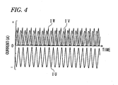
- Fig. 4 shows changes of the phase currents shown in Fig. 3 .
- phase currents flow based on the back electromotive force generated in the electric motor 101.
- a direction of phase currents from the inverter 201 to the electric motor 101 is referred to as positive
- a direction of phase currents from the electric motor 101 to the inverter 201 is referred to as negative.
- a U-phase current IU based on the back electromotive force flows to this switch unit 5b, and a V-phase current IV and a W-phase current IW whose phases are offset through 120 degrees to positive and negative sides, respectively, with respect to the U-phase current IU flow to reflux diodes 4b of the switch units 5b of the other phases.
- a DC component of the U-phase current is offset to an opposite polarity to those of respective DC components of the V-phase current IV and the W-phase current IW.
- the inverter ECU 301 of this embodiment detects a short-circuit failure of the inverter 201 based on respective characteristics of the phase currents. Signals indicating phase currents detected by the phase current sensor 401 are sent to the inverter ECU 301.
- the DC components acquiring unit 501 of the inverter ECU 301 acquires respective DC component values of the phase currents. DC components of the phase currents are obtained by calculating a mean value, an effective value or a center value of the phase currents by the inverter ECU 301 or treating the phase currents with a low-pass filter.
- the short-circuiting determination unit 503 of the inverter ECU 301 determines that the inverter 201 short-circuits and fails when at least one of the DC component values exceeds a threshold Ith in absolute value.
- the phase short-circuiting control unit 505 of the inverter ECU 301 controls all the switching elements provided on either of the positive side or the negative side of the respective arms and off controls all the switching elements provided on the opposite side.
- Fig. 6 shows flow lines of the phase currents when all the switching elements 3a on the positive side of the respective arms are on controlled with the switch unit 5b on the negative side of the U phase short-circuits and fails. Since the on-controlled switching elements are energized, the electric motor 101 is put in a three-phase short-circuited state.
- the inverter ECU 301 maintains this state. No great current flows to the switch unit which short-circuits and fails even thereafter.
- the current flowing through the switching elements 3a and 3b of any of the phases depends on the amount of electric charge of a smoothing capacitor C.
- the rotational speed of the electric motor 101 which is rotated by the internal combustion engine 107 increases, the amount of electric charge accumulated in the smoothing capacitor C also increases.
- Fig. 7 shows flow lines of phase currents when all the switching elements 3b on the negative side are on controlled with the switch unit 5b on the negative side of the U phase shirt-circuiting and failing. The inverter ECU 301 maintains this state.
- a current detection unit Se may be provided between all switch units 5b provided on a negative side and a smoothing capacitor C. As this occurs, when a current detected by the electric current detection unit Se is equal to or smaller than the threshold when the three-phase short-circuiting control unit 505 of the inverter ECU 301 on controls all switching elements on either of the positive side and the negative side of an inverter 203, the inverter ECU 301 maintains that state.
- the three-phase short-circuiting control unit 505 of the inverter ECU 301 off controls all the switching elements of the on-controlled side and on controls all the switching elements of the off-controlled side.
- switching element having a current detection function When switching element having a current detection function are used as switching elements 3 a and 3b of each phase, in place of the current detection units Seu, Sev, Sew or the current detection unit Se, the respective current detection functions of the switching elements may be made used.
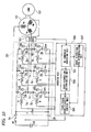
- Fig. 10 is a block diagram showing a system for driving the electric motor 101 which includes an inverter ECU 303 having a short-circuiting side determination unit 507 for determining whether the short-circuited switch unit lies on the positive side or the negative side.
- signals indicating phase currents detected by the phase current sensor 401 are sent to the inverter ECU 303.
- the short-circuiting side determination unit 507 determines a side where the short-circuit failure of the switch unit occurs based on respective polarities of phase current values.
- the short-circuiting side determination unit 507 of the inverter ECU 303 determines the side where the short-circuit failure of the switch unit occurs, three-phase short-circuiting control unit 505 of the inverter ECU 303 on controls the switching elements provided on the side where the short-circuit failure of the switch unit occurs and off controls the switching elements provided on the opposite side. As this occurs, no great current flows to the switch unit which short-circuits and fails. In this case, the three-phase short-circuiting control unit 505 of the inverter ECU 303 does not have to switch on/off controls of the switching elements based on the currents detected by the current detection units Seu, Sev, Sew or Se.
- the inverter ECU 301, 303 detects the short-circuit failure based on the signals from the phase current sensor 401. Further, the inverter ECU 301, 303 on/off controls the switching elements of the inverter 201, 203 so that the three-phase short-circuited state is generated in the electric motor 101 without allowing a great current to flow to the switch unit which short-circuits and fails. In this way, according to the embodiment, even though the control of the electric motor 101 is stopped, the three-phase short-circuiting control can be performed by detecting the short-circuit failure of the inverter 201, 203.
- the inverter ECUs 301, 303 of the first embodiment may not be able to detect the short-circuit failure of the inverters 201, 203 accurately. For example, when a failure occurs in the phase current sensor 401 in which phase currents detected by the phase current sensor 401 stay at larger values than the threshold Ith shown in Fig. 4 , the inverter ECUs 301, 303 erroneously determines that a short-circuit failure is occurring in the inverters 201, 203.
- the inverter ECUs 301, 303 of the above-described first embodiment determine that the inverters 201, 203 short-circuit and fail when at least one of the DC components of the three phase currents exceeds the threshold Ith in absolute value.
- an inverter ECU 305 of a second embodiment determines that the inverters 201, 203 short-circuit and fail by verifying to which of cases below the result of a comparison of the DC components of the three phase currents with the threshold Ith corresponds.
- Case 1 All the DC components of the three phase currents exceed the threshold Ith in absolute value.
- Case 2 Among the DC components of the three phase currents, two exceed the threshold Ith in absolute value, while the remaining one is equal to or smaller than the threshold Ith.
- Case 3 Among the DC components of the three phase currents, one exceeds the threshold Ith in absolute value, while the remaining two are equal to or smaller than the threshold Ith.
- the inverter ECU 305 determines that the phase current sensor 401 functions normal and the short-circuit failure is occurring in the inverters 201, 203. Thereafter, as in the first embodiment, the inverter ECU 305 executes the three-phase short-circuiting control on the electric motor 101.
- the inverter ECU 305 determines that the short-circuit failure is occurring in the inverters 201, 203. As this occurs, the inverter ECU 305 determines that although the short-circuit failure is occurring in the inverters 201, 203, one of the three values is equal to or smaller than the threshold Ith in absolute value due to one of the sensors making up the phase current sensor 401 failing. In addition, in such a case, although there is a possibility that two of the three sensors making up the phase current sensor 401 fail, determining that the short-circuit failure is occurring in the inverters 201, 203, the inverter ECU 305 executes the three-phase short-circuiting control on the electric motor 101.
- the inverter ECU 305 determines that no short-circuit failure is occurring in the inverters 201, 203. As this occurs, the inverter ECU 305 determines that one of the three values exceeds the threshold Ith in absolute value due to one of the sensors making up the phase current sensor 401 failing.
- the inverter ECU 305 of this embodiment determines whether or not the inverters 201, 203 short-circuit and fail in view of the conditions of the phase current sensor 401, and therefore, the inverter ECU 305 can detect the short-circuit failure of the inverters 201, 203 more accurately.
- the rotor of the electric motor 101 is connected directly to the drive shaft of the internal combustion engine 107.
- the invention may be applied to a vehicle as shown in Fig. 13 in which a drive shaft of an internal combustion engine 107 is connected to a gearbox 109 and a drive shaft 151 via a clutch 113 and a drive shaft of an electric motor 101 is connected to the gearbox 109 and the drive shaft 151 without interposing the clutch therebetween.
Landscapes
- Engineering & Computer Science (AREA)
- Power Engineering (AREA)
- Transportation (AREA)
- Mechanical Engineering (AREA)
- Life Sciences & Earth Sciences (AREA)
- Sustainable Development (AREA)
- Sustainable Energy (AREA)
- Inverter Devices (AREA)
- Control Of Ac Motors In General (AREA)
- Electric Propulsion And Braking For Vehicles (AREA)
- Hybrid Electric Vehicles (AREA)
- Control Of Electric Motors In General (AREA)
Applications Claiming Priority (2)
| Application Number | Priority Date | Filing Date | Title |
|---|---|---|---|
| JP2008333639A JP4968698B2 (ja) | 2008-12-26 | 2008-12-26 | 電動機の制御装置 |
| EP09834623A EP2372900A4 (de) | 2008-12-26 | 2009-11-02 | Motorsteuervorrichtung |
Related Parent Applications (2)
| Application Number | Title | Priority Date | Filing Date |
|---|---|---|---|
| EP09834623.2 Division | 2009-11-02 | ||
| EP09834623A Division EP2372900A4 (de) | 2008-12-26 | 2009-11-02 | Motorsteuervorrichtung |
Publications (3)
| Publication Number | Publication Date |
|---|---|
| EP2546980A2 true EP2546980A2 (de) | 2013-01-16 |
| EP2546980A3 EP2546980A3 (de) | 2013-06-26 |
| EP2546980B1 EP2546980B1 (de) | 2014-03-19 |
Family
ID=42287444
Family Applications (2)
| Application Number | Title | Priority Date | Filing Date |
|---|---|---|---|
| EP09834623A Withdrawn EP2372900A4 (de) | 2008-12-26 | 2009-11-02 | Motorsteuervorrichtung |
| EP12187918.3A Not-in-force EP2546980B1 (de) | 2008-12-26 | 2009-11-02 | Elektromotorsteuerungssystem |
Family Applications Before (1)
| Application Number | Title | Priority Date | Filing Date |
|---|---|---|---|
| EP09834623A Withdrawn EP2372900A4 (de) | 2008-12-26 | 2009-11-02 | Motorsteuervorrichtung |
Country Status (6)
| Country | Link |
|---|---|
| US (1) | US8598826B2 (de) |
| EP (2) | EP2372900A4 (de) |
| JP (1) | JP4968698B2 (de) |
| CN (1) | CN102257724B (de) |
| BR (1) | BRPI0923687A2 (de) |
| WO (1) | WO2010073819A1 (de) |
Cited By (1)
| Publication number | Priority date | Publication date | Assignee | Title |
|---|---|---|---|---|
| DE102014115881B4 (de) * | 2013-11-06 | 2021-03-25 | GM Global Technology Operations LLC (n. d. Gesetzen des Staates Delaware) | Verfahren und Vorrichtung zum Vergrössern eines Stromerfassungsbereichs in einem System mit einem mehrphasigen Motor |
Families Citing this family (40)
| Publication number | Priority date | Publication date | Assignee | Title |
|---|---|---|---|---|
| JP5365431B2 (ja) * | 2009-09-04 | 2013-12-11 | 三菱電機株式会社 | エレベータの制御装置 |
| JP4962583B2 (ja) * | 2010-03-11 | 2012-06-27 | 株式会社デンソー | 電力変換システムの放電制御装置 |
| JP5923955B2 (ja) * | 2011-12-06 | 2016-05-25 | 株式会社デンソー | 多相回転機の制御装置 |
| JP5465269B2 (ja) * | 2012-03-29 | 2014-04-09 | 三菱電機株式会社 | 故障検出回路を備えた電動機駆動装置および電動機駆動装置の故障検出方法 |
| CN104106205B (zh) * | 2012-03-30 | 2017-05-31 | 富士电机株式会社 | 交流电机系统及其控制方法 |
| JP5945692B2 (ja) * | 2012-07-03 | 2016-07-05 | パナソニックIpマネジメント株式会社 | インバータ装置 |
| CN103066556B (zh) * | 2012-12-04 | 2017-03-29 | 联合汽车电子有限公司 | 高压直流系统的过压保护方法 |
| JP6155708B2 (ja) * | 2013-03-08 | 2017-07-05 | 株式会社ジェイテクト | モータ制御装置 |
| JP5876846B2 (ja) * | 2013-03-13 | 2016-03-02 | 東芝三菱電機産業システム株式会社 | 電動機駆動装置 |
| FR3005222B1 (fr) * | 2013-04-26 | 2015-04-17 | Valeo Sys Controle Moteur Sas | Architecture electronique pour la commande d'un convertisseur de tension continu/alternatif |
| JP6056734B2 (ja) * | 2013-10-25 | 2017-01-11 | トヨタ自動車株式会社 | 車両制御装置 |
| DE102013226560A1 (de) | 2013-12-19 | 2015-06-25 | Robert Bosch Gmbh | Vorrichtung und Verfahren zum Betreiben einer elektrischen Maschine |
| US9889880B2 (en) | 2014-03-11 | 2018-02-13 | Nsk Ltd. | Motor control device, electric power steering device using same, and vehicle |
| JP6173564B2 (ja) * | 2014-03-18 | 2017-08-02 | 日立建機株式会社 | 作業機械 |
| EP3128669B1 (de) * | 2014-04-03 | 2020-09-09 | Fuji Electric Co., Ltd. | Sicherheitssteuerungsvorrichtung |
| JP2015223050A (ja) * | 2014-05-23 | 2015-12-10 | ファナック株式会社 | インバータ及び動力線の故障検出機能を備えたモータ駆動装置 |
| JP6327141B2 (ja) * | 2014-12-24 | 2018-05-23 | トヨタ自動車株式会社 | 電動車両 |
| KR102281672B1 (ko) * | 2015-04-02 | 2021-07-27 | 주식회사 만도 | Eps 전자제어장치 및 제어방법 |
| JP6237699B2 (ja) | 2015-05-25 | 2017-11-29 | トヨタ自動車株式会社 | 異常検出装置 |
| EP3131198B1 (de) * | 2015-08-10 | 2022-06-08 | Goodrich Actuation Systems Limited | Steuerungsstrategie eines zweiwegigen fehlertoleranten permanentmagnetmotors zur reduzierung des schleppmoments unter störung |
| JP6252569B2 (ja) * | 2015-09-10 | 2017-12-27 | トヨタ自動車株式会社 | ハイブリッド車両 |
| JP6518604B2 (ja) * | 2016-02-24 | 2019-05-22 | 本田技研工業株式会社 | 電源装置、機器及び制御方法 |
| JP6461838B2 (ja) * | 2016-02-24 | 2019-01-30 | 本田技研工業株式会社 | 電源装置、機器及び制御方法 |
| JP6642201B2 (ja) * | 2016-03-30 | 2020-02-05 | 株式会社デンソー | モータ制御装置及びモータ制御プログラム |
| JP2017190029A (ja) * | 2016-04-12 | 2017-10-19 | トヨタ自動車株式会社 | ハイブリッド車両の制御装置 |
| JP6418196B2 (ja) * | 2016-04-15 | 2018-11-07 | トヨタ自動車株式会社 | 電気自動車 |
| JP6230677B1 (ja) * | 2016-10-20 | 2017-11-15 | 三菱電機株式会社 | 回転電機の制御装置および制御方法 |
| JP6610586B2 (ja) * | 2017-03-13 | 2019-11-27 | トヨタ自動車株式会社 | 駆動装置 |
| JP6824103B2 (ja) * | 2017-04-25 | 2021-02-03 | 三菱電機株式会社 | 電力半導体装置および電力半導体駆動システム |
| JP6818155B2 (ja) * | 2017-09-05 | 2021-01-20 | 株式会社日立製作所 | 交流電動機の監視装置および監視方法、ならびに電動機駆動システムの監視装置および監視方法 |
| DE102017218189A1 (de) * | 2017-10-12 | 2019-04-18 | Zf Friedrichshafen Ag | Sicherer Zustand einer elektrischen Maschine |
| JP6947016B2 (ja) * | 2017-12-26 | 2021-10-13 | 株式会社デンソー | 電動車両 |
| JP7006428B2 (ja) * | 2018-03-23 | 2022-01-24 | 株式会社デンソー | モータ制御装置 |
| CN112848900B (zh) * | 2019-11-26 | 2024-07-05 | 松下汽车电子系统株式会社 | 车辆驱动装置 |
| TWI721829B (zh) * | 2020-03-18 | 2021-03-11 | 李岳翰 | 於車輛停止時增加車輪阻力的方法及車輛增阻裝置 |
| CN112083348B (zh) * | 2020-07-24 | 2023-05-23 | 苏州汇川联合动力系统有限公司 | 电机单相对地短路的检测方法、系统和存储介质 |
| EP4325711A4 (de) * | 2021-04-14 | 2024-05-29 | Mitsubishi Electric Corporation | Leistungswandler |
| JP7590943B2 (ja) * | 2021-09-10 | 2024-11-27 | 日立Astemo株式会社 | モータ駆動装置および電動車両 |
| JP7703993B2 (ja) * | 2021-10-13 | 2025-07-08 | 富士電機株式会社 | 電力変換装置の短絡保護装置 |
| KR20230174023A (ko) * | 2022-06-20 | 2023-12-27 | 현대자동차주식회사 | 인버터 구동 장치 및 이의 제어 방법 |
Citations (1)
| Publication number | Priority date | Publication date | Assignee | Title |
|---|---|---|---|---|
| JP2008220045A (ja) | 2007-03-05 | 2008-09-18 | Honda Motor Co Ltd | 電動機の制御装置および車両 |
Family Cites Families (9)
| Publication number | Priority date | Publication date | Assignee | Title |
|---|---|---|---|---|
| JPH0759384A (ja) | 1993-08-19 | 1995-03-03 | Toshiba Corp | インバータ装置 |
| US5998880A (en) * | 1997-08-07 | 1999-12-07 | General Electric Company | AC locomotive operation without DC current sensor |
| JP4000866B2 (ja) * | 2002-02-22 | 2007-10-31 | アイシン・エィ・ダブリュ株式会社 | 駆動用電源装置及びフェール判定方法 |
| US6683435B1 (en) * | 2002-06-21 | 2004-01-27 | Ford Motor Company | Electrical machine drive method and system |
| JP2006184160A (ja) * | 2004-12-28 | 2006-07-13 | Nissan Motor Co Ltd | 故障検出機能付き三相交流電動機の電流検出装置 |
| US7276871B2 (en) * | 2005-07-25 | 2007-10-02 | Honeywell International, Inc. | System and method for fault protection for permanent magnet machines |
| JP3927584B2 (ja) * | 2005-10-26 | 2007-06-13 | 三菱電機株式会社 | 自動車用動力制御装置 |
| JP4784478B2 (ja) * | 2006-04-20 | 2011-10-05 | 株式会社デンソー | 多相回転電機の制御装置 |
| JP4747968B2 (ja) * | 2006-06-30 | 2011-08-17 | トヨタ自動車株式会社 | モータ駆動装置 |
-
2008
- 2008-12-26 JP JP2008333639A patent/JP4968698B2/ja not_active Expired - Fee Related
-
2009
- 2009-11-02 WO PCT/JP2009/068784 patent/WO2010073819A1/ja not_active Ceased
- 2009-11-02 EP EP09834623A patent/EP2372900A4/de not_active Withdrawn
- 2009-11-02 EP EP12187918.3A patent/EP2546980B1/de not_active Not-in-force
- 2009-11-02 CN CN200980151526.7A patent/CN102257724B/zh not_active Expired - Fee Related
- 2009-11-02 US US13/139,353 patent/US8598826B2/en active Active
- 2009-11-02 BR BRPI0923687-2A patent/BRPI0923687A2/pt active Search and Examination
Patent Citations (1)
| Publication number | Priority date | Publication date | Assignee | Title |
|---|---|---|---|---|
| JP2008220045A (ja) | 2007-03-05 | 2008-09-18 | Honda Motor Co Ltd | 電動機の制御装置および車両 |
Cited By (1)
| Publication number | Priority date | Publication date | Assignee | Title |
|---|---|---|---|---|
| DE102014115881B4 (de) * | 2013-11-06 | 2021-03-25 | GM Global Technology Operations LLC (n. d. Gesetzen des Staates Delaware) | Verfahren und Vorrichtung zum Vergrössern eines Stromerfassungsbereichs in einem System mit einem mehrphasigen Motor |
Also Published As
| Publication number | Publication date |
|---|---|
| US20110241589A1 (en) | 2011-10-06 |
| EP2372900A1 (de) | 2011-10-05 |
| CN102257724A (zh) | 2011-11-23 |
| WO2010073819A1 (ja) | 2010-07-01 |
| JP2010158089A (ja) | 2010-07-15 |
| CN102257724B (zh) | 2014-05-21 |
| US8598826B2 (en) | 2013-12-03 |
| EP2546980A3 (de) | 2013-06-26 |
| EP2546980B1 (de) | 2014-03-19 |
| EP2372900A4 (de) | 2012-06-06 |
| BRPI0923687A2 (pt) | 2020-08-11 |
| JP4968698B2 (ja) | 2012-07-04 |
Similar Documents
| Publication | Publication Date | Title |
|---|---|---|
| US8598826B2 (en) | Electric motor control system | |
| US8045301B2 (en) | Motor drive device | |
| US11387766B2 (en) | Control circuit for electric power converter | |
| US10110154B2 (en) | Controller and a method to drive an inverter circuit for a permanent-magnet synchronous motor | |
| US20220115975A1 (en) | Motor control method and circuit for vehicle, motor drive system, and vehicle | |
| JP4757815B2 (ja) | 電動機の制御装置および車両 | |
| CN111108681B (zh) | 逆变器控制装置 | |
| US6239566B1 (en) | Drive system for a permanently excited electric motor having at least one phase winding | |
| US9054626B2 (en) | Motor control apparatus | |
| JP4926222B2 (ja) | 車両用電力変換器の制御装置 | |
| CN102958742B (zh) | 用于使在机动车中具有至少三相电机的驱动设备运行的方法和用于逆变器的控制器 | |
| US20120020136A1 (en) | Electric Power Conversion System | |
| US20090195199A1 (en) | Motor drive device | |
| JP2019122238A (ja) | モータ制御装置およびモータ制御装置の制御方法 | |
| JP2019134590A (ja) | インバータ制御装置 | |
| US20150015168A1 (en) | Vehicular driving system | |
| CN110505972A (zh) | 车辆 | |
| US20050226298A1 (en) | Power conversion device | |
| CN110022116A (zh) | 电动机控制装置和电动机控制装置的控制方法 | |
| US7514906B1 (en) | Automotive rotary electrical apparatus | |
| KR101044234B1 (ko) | 플러그인 하이브리드 차량용 오일펌프 구동방법 | |
| JP5269567B2 (ja) | 電動機の制御装置及び車両 | |
| JP6854429B2 (ja) | 車両駆動装置 | |
| CN111572329B (zh) | 车辆驱动装置 | |
| JP2020178522A (ja) | 回転電機システム |
Legal Events
| Date | Code | Title | Description |
|---|---|---|---|
| PUAI | Public reference made under article 153(3) epc to a published international application that has entered the european phase |
Free format text: ORIGINAL CODE: 0009012 |
|
| 17P | Request for examination filed |
Effective date: 20121010 |
|
| AC | Divisional application: reference to earlier application |
Ref document number: 2372900 Country of ref document: EP Kind code of ref document: P |
|
| AK | Designated contracting states |
Kind code of ref document: A2 Designated state(s): AT BE BG CH CY CZ DE DK EE ES FI FR GB GR HR HU IE IS IT LI LT LU LV MC MK MT NL NO PL PT RO SE SI SK SM TR |
|
| PUAL | Search report despatched |
Free format text: ORIGINAL CODE: 0009013 |
|
| AK | Designated contracting states |
Kind code of ref document: A3 Designated state(s): AT BE BG CH CY CZ DE DK EE ES FI FR GB GR HR HU IE IS IT LI LT LU LV MC MK MT NL NO PL PT RO SE SI SK SM TR |
|
| RIC1 | Information provided on ipc code assigned before grant |
Ipc: H02M 7/48 20070101ALI20130517BHEP Ipc: B60L 3/00 20060101ALI20130517BHEP Ipc: H02M 1/00 20070101ALI20130517BHEP Ipc: H02P 27/06 20060101AFI20130517BHEP Ipc: B60L 11/14 20060101ALI20130517BHEP Ipc: H02P 29/02 20060101ALI20130517BHEP |
|
| GRAP | Despatch of communication of intention to grant a patent |
Free format text: ORIGINAL CODE: EPIDOSNIGR1 |
|
| RIC1 | Information provided on ipc code assigned before grant |
Ipc: B60L 11/14 20060101ALI20131022BHEP Ipc: H02P 29/02 20060101ALI20131022BHEP Ipc: H02M 1/00 20070101ALI20131022BHEP Ipc: H02P 27/06 20060101AFI20131022BHEP Ipc: B60L 3/00 20060101ALI20131022BHEP Ipc: H02M 7/48 20070101ALI20131022BHEP |
|
| INTG | Intention to grant announced |
Effective date: 20131127 |
|
| GRAS | Grant fee paid |
Free format text: ORIGINAL CODE: EPIDOSNIGR3 |
|
| GRAA | (expected) grant |
Free format text: ORIGINAL CODE: 0009210 |
|
| AC | Divisional application: reference to earlier application |
Ref document number: 2372900 Country of ref document: EP Kind code of ref document: P |
|
| AK | Designated contracting states |
Kind code of ref document: B1 Designated state(s): AT BE BG CH CY CZ DE DK EE ES FI FR GB GR HR HU IE IS IT LI LT LU LV MC MK MT NL NO PL PT RO SE SI SK SM TR |
|
| REG | Reference to a national code |
Ref country code: GB Ref legal event code: FG4D |
|
| REG | Reference to a national code |
Ref country code: CH Ref legal event code: EP |
|
| REG | Reference to a national code |
Ref country code: AT Ref legal event code: REF Ref document number: 658246 Country of ref document: AT Kind code of ref document: T Effective date: 20140415 |
|
| REG | Reference to a national code |
Ref country code: IE Ref legal event code: FG4D |
|
| REG | Reference to a national code |
Ref country code: DE Ref legal event code: R096 Ref document number: 602009022695 Country of ref document: DE Effective date: 20140430 |
|
| PG25 | Lapsed in a contracting state [announced via postgrant information from national office to epo] |
Ref country code: LT Free format text: LAPSE BECAUSE OF FAILURE TO SUBMIT A TRANSLATION OF THE DESCRIPTION OR TO PAY THE FEE WITHIN THE PRESCRIBED TIME-LIMIT Effective date: 20140319 Ref country code: NO Free format text: LAPSE BECAUSE OF FAILURE TO SUBMIT A TRANSLATION OF THE DESCRIPTION OR TO PAY THE FEE WITHIN THE PRESCRIBED TIME-LIMIT Effective date: 20140619 |
|
| REG | Reference to a national code |
Ref country code: NL Ref legal event code: VDEP Effective date: 20140319 |
|
| REG | Reference to a national code |
Ref country code: AT Ref legal event code: MK05 Ref document number: 658246 Country of ref document: AT Kind code of ref document: T Effective date: 20140319 |
|
| REG | Reference to a national code |
Ref country code: LT Ref legal event code: MG4D |
|
| PG25 | Lapsed in a contracting state [announced via postgrant information from national office to epo] |
Ref country code: FI Free format text: LAPSE BECAUSE OF FAILURE TO SUBMIT A TRANSLATION OF THE DESCRIPTION OR TO PAY THE FEE WITHIN THE PRESCRIBED TIME-LIMIT Effective date: 20140319 Ref country code: SE Free format text: LAPSE BECAUSE OF FAILURE TO SUBMIT A TRANSLATION OF THE DESCRIPTION OR TO PAY THE FEE WITHIN THE PRESCRIBED TIME-LIMIT Effective date: 20140319 Ref country code: CY Free format text: LAPSE BECAUSE OF FAILURE TO SUBMIT A TRANSLATION OF THE DESCRIPTION OR TO PAY THE FEE WITHIN THE PRESCRIBED TIME-LIMIT Effective date: 20140319 |
|
| PG25 | Lapsed in a contracting state [announced via postgrant information from national office to epo] |
Ref country code: LV Free format text: LAPSE BECAUSE OF FAILURE TO SUBMIT A TRANSLATION OF THE DESCRIPTION OR TO PAY THE FEE WITHIN THE PRESCRIBED TIME-LIMIT Effective date: 20140319 Ref country code: HR Free format text: LAPSE BECAUSE OF FAILURE TO SUBMIT A TRANSLATION OF THE DESCRIPTION OR TO PAY THE FEE WITHIN THE PRESCRIBED TIME-LIMIT Effective date: 20140319 |
|
| PG25 | Lapsed in a contracting state [announced via postgrant information from national office to epo] |
Ref country code: EE Free format text: LAPSE BECAUSE OF FAILURE TO SUBMIT A TRANSLATION OF THE DESCRIPTION OR TO PAY THE FEE WITHIN THE PRESCRIBED TIME-LIMIT Effective date: 20140319 Ref country code: NL Free format text: LAPSE BECAUSE OF FAILURE TO SUBMIT A TRANSLATION OF THE DESCRIPTION OR TO PAY THE FEE WITHIN THE PRESCRIBED TIME-LIMIT Effective date: 20140319 Ref country code: RO Free format text: LAPSE BECAUSE OF FAILURE TO SUBMIT A TRANSLATION OF THE DESCRIPTION OR TO PAY THE FEE WITHIN THE PRESCRIBED TIME-LIMIT Effective date: 20140319 Ref country code: IS Free format text: LAPSE BECAUSE OF FAILURE TO SUBMIT A TRANSLATION OF THE DESCRIPTION OR TO PAY THE FEE WITHIN THE PRESCRIBED TIME-LIMIT Effective date: 20140719 Ref country code: CZ Free format text: LAPSE BECAUSE OF FAILURE TO SUBMIT A TRANSLATION OF THE DESCRIPTION OR TO PAY THE FEE WITHIN THE PRESCRIBED TIME-LIMIT Effective date: 20140319 Ref country code: BG Free format text: LAPSE BECAUSE OF FAILURE TO SUBMIT A TRANSLATION OF THE DESCRIPTION OR TO PAY THE FEE WITHIN THE PRESCRIBED TIME-LIMIT Effective date: 20140619 Ref country code: BE Free format text: LAPSE BECAUSE OF FAILURE TO SUBMIT A TRANSLATION OF THE DESCRIPTION OR TO PAY THE FEE WITHIN THE PRESCRIBED TIME-LIMIT Effective date: 20140319 |
|
| PG25 | Lapsed in a contracting state [announced via postgrant information from national office to epo] |
Ref country code: PL Free format text: LAPSE BECAUSE OF FAILURE TO SUBMIT A TRANSLATION OF THE DESCRIPTION OR TO PAY THE FEE WITHIN THE PRESCRIBED TIME-LIMIT Effective date: 20140319 Ref country code: ES Free format text: LAPSE BECAUSE OF FAILURE TO SUBMIT A TRANSLATION OF THE DESCRIPTION OR TO PAY THE FEE WITHIN THE PRESCRIBED TIME-LIMIT Effective date: 20140319 Ref country code: SK Free format text: LAPSE BECAUSE OF FAILURE TO SUBMIT A TRANSLATION OF THE DESCRIPTION OR TO PAY THE FEE WITHIN THE PRESCRIBED TIME-LIMIT Effective date: 20140319 Ref country code: AT Free format text: LAPSE BECAUSE OF FAILURE TO SUBMIT A TRANSLATION OF THE DESCRIPTION OR TO PAY THE FEE WITHIN THE PRESCRIBED TIME-LIMIT Effective date: 20140319 |
|
| REG | Reference to a national code |
Ref country code: DE Ref legal event code: R097 Ref document number: 602009022695 Country of ref document: DE |
|
| PG25 | Lapsed in a contracting state [announced via postgrant information from national office to epo] |
Ref country code: PT Free format text: LAPSE BECAUSE OF FAILURE TO SUBMIT A TRANSLATION OF THE DESCRIPTION OR TO PAY THE FEE WITHIN THE PRESCRIBED TIME-LIMIT Effective date: 20140721 |
|
| PLBE | No opposition filed within time limit |
Free format text: ORIGINAL CODE: 0009261 |
|
| STAA | Information on the status of an ep patent application or granted ep patent |
Free format text: STATUS: NO OPPOSITION FILED WITHIN TIME LIMIT |
|
| PG25 | Lapsed in a contracting state [announced via postgrant information from national office to epo] |
Ref country code: DK Free format text: LAPSE BECAUSE OF FAILURE TO SUBMIT A TRANSLATION OF THE DESCRIPTION OR TO PAY THE FEE WITHIN THE PRESCRIBED TIME-LIMIT Effective date: 20140319 |
|
| 26N | No opposition filed |
Effective date: 20141222 |
|
| PG25 | Lapsed in a contracting state [announced via postgrant information from national office to epo] |
Ref country code: IT Free format text: LAPSE BECAUSE OF FAILURE TO SUBMIT A TRANSLATION OF THE DESCRIPTION OR TO PAY THE FEE WITHIN THE PRESCRIBED TIME-LIMIT Effective date: 20140319 |
|
| REG | Reference to a national code |
Ref country code: DE Ref legal event code: R097 Ref document number: 602009022695 Country of ref document: DE Effective date: 20141222 |
|
| PG25 | Lapsed in a contracting state [announced via postgrant information from national office to epo] |
Ref country code: LU Free format text: LAPSE BECAUSE OF FAILURE TO SUBMIT A TRANSLATION OF THE DESCRIPTION OR TO PAY THE FEE WITHIN THE PRESCRIBED TIME-LIMIT Effective date: 20141102 Ref country code: MC Free format text: LAPSE BECAUSE OF FAILURE TO SUBMIT A TRANSLATION OF THE DESCRIPTION OR TO PAY THE FEE WITHIN THE PRESCRIBED TIME-LIMIT Effective date: 20140319 |
|
| REG | Reference to a national code |
Ref country code: CH Ref legal event code: PL |
|
| GBPC | Gb: european patent ceased through non-payment of renewal fee |
Effective date: 20141102 |
|
| PG25 | Lapsed in a contracting state [announced via postgrant information from national office to epo] |
Ref country code: CH Free format text: LAPSE BECAUSE OF NON-PAYMENT OF DUE FEES Effective date: 20141130 Ref country code: SI Free format text: LAPSE BECAUSE OF FAILURE TO SUBMIT A TRANSLATION OF THE DESCRIPTION OR TO PAY THE FEE WITHIN THE PRESCRIBED TIME-LIMIT Effective date: 20140319 Ref country code: LI Free format text: LAPSE BECAUSE OF NON-PAYMENT OF DUE FEES Effective date: 20141130 |
|
| REG | Reference to a national code |
Ref country code: IE Ref legal event code: MM4A |
|
| PG25 | Lapsed in a contracting state [announced via postgrant information from national office to epo] |
Ref country code: GB Free format text: LAPSE BECAUSE OF NON-PAYMENT OF DUE FEES Effective date: 20141102 Ref country code: IE Free format text: LAPSE BECAUSE OF NON-PAYMENT OF DUE FEES Effective date: 20141102 |
|
| REG | Reference to a national code |
Ref country code: FR Ref legal event code: PLFP Year of fee payment: 7 |
|
| PG25 | Lapsed in a contracting state [announced via postgrant information from national office to epo] |
Ref country code: SM Free format text: LAPSE BECAUSE OF FAILURE TO SUBMIT A TRANSLATION OF THE DESCRIPTION OR TO PAY THE FEE WITHIN THE PRESCRIBED TIME-LIMIT Effective date: 20140319 |
|
| PG25 | Lapsed in a contracting state [announced via postgrant information from national office to epo] |
Ref country code: GR Free format text: LAPSE BECAUSE OF FAILURE TO SUBMIT A TRANSLATION OF THE DESCRIPTION OR TO PAY THE FEE WITHIN THE PRESCRIBED TIME-LIMIT Effective date: 20140620 |
|
| PG25 | Lapsed in a contracting state [announced via postgrant information from national office to epo] |
Ref country code: TR Free format text: LAPSE BECAUSE OF FAILURE TO SUBMIT A TRANSLATION OF THE DESCRIPTION OR TO PAY THE FEE WITHIN THE PRESCRIBED TIME-LIMIT Effective date: 20140319 Ref country code: HU Free format text: LAPSE BECAUSE OF FAILURE TO SUBMIT A TRANSLATION OF THE DESCRIPTION OR TO PAY THE FEE WITHIN THE PRESCRIBED TIME-LIMIT; INVALID AB INITIO Effective date: 20091102 Ref country code: MT Free format text: LAPSE BECAUSE OF FAILURE TO SUBMIT A TRANSLATION OF THE DESCRIPTION OR TO PAY THE FEE WITHIN THE PRESCRIBED TIME-LIMIT Effective date: 20140319 |
|
| REG | Reference to a national code |
Ref country code: FR Ref legal event code: PLFP Year of fee payment: 8 |
|
| PGFP | Annual fee paid to national office [announced via postgrant information from national office to epo] |
Ref country code: FR Payment date: 20161124 Year of fee payment: 8 |
|
| PG25 | Lapsed in a contracting state [announced via postgrant information from national office to epo] |
Ref country code: MK Free format text: LAPSE BECAUSE OF FAILURE TO SUBMIT A TRANSLATION OF THE DESCRIPTION OR TO PAY THE FEE WITHIN THE PRESCRIBED TIME-LIMIT Effective date: 20140319 |
|
| REG | Reference to a national code |
Ref country code: DE Ref legal event code: R084 Ref document number: 602009022695 Country of ref document: DE |
|
| REG | Reference to a national code |
Ref country code: FR Ref legal event code: ST Effective date: 20180731 |
|
| PG25 | Lapsed in a contracting state [announced via postgrant information from national office to epo] |
Ref country code: FR Free format text: LAPSE BECAUSE OF NON-PAYMENT OF DUE FEES Effective date: 20171130 |
|
| PGFP | Annual fee paid to national office [announced via postgrant information from national office to epo] |
Ref country code: DE Payment date: 20201020 Year of fee payment: 12 |
|
| REG | Reference to a national code |
Ref country code: DE Ref legal event code: R119 Ref document number: 602009022695 Country of ref document: DE |
|
| PG25 | Lapsed in a contracting state [announced via postgrant information from national office to epo] |
Ref country code: DE Free format text: LAPSE BECAUSE OF NON-PAYMENT OF DUE FEES Effective date: 20220601 |