EP2548652B1 - Verfahren zum sprühen mit einer düse sowie düse - Google Patents
Verfahren zum sprühen mit einer düse sowie düse Download PDFInfo
- Publication number
- EP2548652B1 EP2548652B1 EP10847960.1A EP10847960A EP2548652B1 EP 2548652 B1 EP2548652 B1 EP 2548652B1 EP 10847960 A EP10847960 A EP 10847960A EP 2548652 B1 EP2548652 B1 EP 2548652B1
- Authority
- EP
- European Patent Office
- Prior art keywords
- liquid
- air
- pressure
- nozzle
- spray
- Prior art date
- Legal status (The legal status is an assumption and is not a legal conclusion. Google has not performed a legal analysis and makes no representation as to the accuracy of the status listed.)
- Active
Links
Images




Classifications
-
- B—PERFORMING OPERATIONS; TRANSPORTING
- B01—PHYSICAL OR CHEMICAL PROCESSES OR APPARATUS IN GENERAL
- B01F—MIXING, e.g. DISSOLVING, EMULSIFYING OR DISPERSING
- B01F23/00—Mixing according to the phases to be mixed, e.g. dispersing or emulsifying
- B01F23/20—Mixing gases with liquids
- B01F23/23—Mixing gases with liquids by introducing gases into liquid media, e.g. for producing aerated liquids
- B01F23/232—Mixing gases with liquids by introducing gases into liquid media, e.g. for producing aerated liquids using flow-mixing means for introducing the gases, e.g. baffles
-
- B—PERFORMING OPERATIONS; TRANSPORTING
- B05—SPRAYING OR ATOMISING IN GENERAL; APPLYING FLUENT MATERIALS TO SURFACES, IN GENERAL
- B05B—SPRAYING APPARATUS; ATOMISING APPARATUS; NOZZLES
- B05B7/00—Spraying apparatus for discharge of liquids or other fluent materials from two or more sources, e.g. of liquid and air, of powder and gas
- B05B7/02—Spray pistols; Apparatus for discharge
- B05B7/04—Spray pistols; Apparatus for discharge with arrangements for mixing liquids or other fluent materials before discharge
- B05B7/0416—Spray pistols; Apparatus for discharge with arrangements for mixing liquids or other fluent materials before discharge with arrangements for mixing one gas and one liquid
-
- B—PERFORMING OPERATIONS; TRANSPORTING
- B01—PHYSICAL OR CHEMICAL PROCESSES OR APPARATUS IN GENERAL
- B01F—MIXING, e.g. DISSOLVING, EMULSIFYING OR DISPERSING
- B01F23/00—Mixing according to the phases to be mixed, e.g. dispersing or emulsifying
- B01F23/20—Mixing gases with liquids
- B01F23/21—Mixing gases with liquids by introducing liquids into gaseous media
-
- B—PERFORMING OPERATIONS; TRANSPORTING
- B01—PHYSICAL OR CHEMICAL PROCESSES OR APPARATUS IN GENERAL
- B01F—MIXING, e.g. DISSOLVING, EMULSIFYING OR DISPERSING
- B01F25/00—Flow mixers; Mixers for falling materials, e.g. solid particles
- B01F25/30—Injector mixers
- B01F25/31—Injector mixers in conduits or tubes through which the main component flows
- B01F25/312—Injector mixers in conduits or tubes through which the main component flows with Venturi elements; Details thereof
- B01F25/3124—Injector mixers in conduits or tubes through which the main component flows with Venturi elements; Details thereof characterised by the place of introduction of the main flow
- B01F25/31242—Injector mixers in conduits or tubes through which the main component flows with Venturi elements; Details thereof characterised by the place of introduction of the main flow the main flow being injected in the central area of the venturi, creating an aspiration in the circumferential part of the conduit
-
- B—PERFORMING OPERATIONS; TRANSPORTING
- B05—SPRAYING OR ATOMISING IN GENERAL; APPLYING FLUENT MATERIALS TO SURFACES, IN GENERAL
- B05B—SPRAYING APPARATUS; ATOMISING APPARATUS; NOZZLES
- B05B7/00—Spraying apparatus for discharge of liquids or other fluent materials from two or more sources, e.g. of liquid and air, of powder and gas
- B05B7/02—Spray pistols; Apparatus for discharge
- B05B7/08—Spray pistols; Apparatus for discharge with separate outlet orifices, e.g. to form parallel jets, i.e. the axis of the jets being parallel, to form intersecting jets, i.e. the axis of the jets converging but not necessarily intersecting at a point
- B05B7/0807—Spray pistols; Apparatus for discharge with separate outlet orifices, e.g. to form parallel jets, i.e. the axis of the jets being parallel, to form intersecting jets, i.e. the axis of the jets converging but not necessarily intersecting at a point to form intersecting jets
- B05B7/0846—Spray pistols; Apparatus for discharge with separate outlet orifices, e.g. to form parallel jets, i.e. the axis of the jets being parallel, to form intersecting jets, i.e. the axis of the jets converging but not necessarily intersecting at a point to form intersecting jets with jets being only jets constituted by a liquid or a mixture containing a liquid
-
- B—PERFORMING OPERATIONS; TRANSPORTING
- B05—SPRAYING OR ATOMISING IN GENERAL; APPLYING FLUENT MATERIALS TO SURFACES, IN GENERAL
- B05B—SPRAYING APPARATUS; ATOMISING APPARATUS; NOZZLES
- B05B7/00—Spraying apparatus for discharge of liquids or other fluent materials from two or more sources, e.g. of liquid and air, of powder and gas
- B05B7/02—Spray pistols; Apparatus for discharge
- B05B7/12—Spray pistols; Apparatus for discharge designed to control volume of flow, e.g. with adjustable passages
-
- B—PERFORMING OPERATIONS; TRANSPORTING
- B22—CASTING; POWDER METALLURGY
- B22D—CASTING OF METALS; CASTING OF OTHER SUBSTANCES BY THE SAME PROCESSES OR DEVICES
- B22D11/00—Continuous casting of metals, i.e. casting in indefinite lengths
- B22D11/12—Accessories for subsequent treating or working cast stock in situ
- B22D11/124—Accessories for subsequent treating or working cast stock in situ for cooling
- B22D11/1246—Nozzles; Spray heads
-
- B—PERFORMING OPERATIONS; TRANSPORTING
- B01—PHYSICAL OR CHEMICAL PROCESSES OR APPARATUS IN GENERAL
- B01F—MIXING, e.g. DISSOLVING, EMULSIFYING OR DISPERSING
- B01F25/00—Flow mixers; Mixers for falling materials, e.g. solid particles
- B01F2025/91—Direction of flow or arrangement of feed and discharge openings
- B01F2025/915—Reverse flow, i.e. flow changing substantially 180° in direction
-
- B—PERFORMING OPERATIONS; TRANSPORTING
- B05—SPRAYING OR ATOMISING IN GENERAL; APPLYING FLUENT MATERIALS TO SURFACES, IN GENERAL
- B05B—SPRAYING APPARATUS; ATOMISING APPARATUS; NOZZLES
- B05B7/00—Spraying apparatus for discharge of liquids or other fluent materials from two or more sources, e.g. of liquid and air, of powder and gas
- B05B7/02—Spray pistols; Apparatus for discharge
- B05B7/025—Nozzles having elongated outlets, e.g. slots, for the material to be sprayed
Definitions
- the present invention relates to a nozzle and more particularly to a nozzle preferably used to cool slab, bloom, billet, and a roller having high temperatures.
- Continuous casting equipment produces a wide variety of steel plates. It is necessary to adjust the amount of spray jetted from the nozzle according to the kind of a steel plate. Either single fluid nozzle which sprays only water or a binary fluid nozzle which sprays a mixture of water and air is hitherto used.Of these nozzles, it is often the case that a binary fluid consisting of the mixture of water and air is sprayed from the nozzle because the binary fluid spray allows the amount of spray to be easily adjusted by changing the balance between the pressure of the liquid and that of the air to be supplied to the nozzle.
- a nozzle 100 shown in Fig. 12 is conventionally used.
- an orifice 103 is formed at the front end of an independent hole 102 formed along the axis of the nozzle 100, and a cutout portion 104 communicating with the orifice 103 is formed at a jetting side to form a jet port.
- the nozzle 100 has a problem that with a change of the spray amount of the nozzle 100, a spray angle and a flow rate distribution change and as a result, a uniform cooling cannot be performed. More specifically, in spraying the mixture of water and air from the nozzle 100, when the ratio of the flow rate of air to that of water is decreased and finally only water is jetted to lower the flow rate of the water, the spray angle in the spray width direction and that in the spray thickness direction become small. That is, the spray angle is liable to become unstable.
- the binary fluid nozzle 105 which sprays the mixture of the liquid (water) and the air is disclosed in Japanese Examined Patent Application Publication No. 3-15493 shown in Fig. 13 .
- the nozzle tip 106 is mounted at the front end of the adaptor 109 into which the mixture of the liquid and the gas flows.
- the sectionally circular stirring chamber 107 is formed at the nozzle tip 106.
- a front portion 106a of side wall of the stirring chamber 107 is inclined to an opposite direction.
- Two inlets 108 opposed to each other are formed on the side wall of the stirring chamber 107.
- the spray amount is changed by adjusting the balance between the pressure of the liquid and that of the air to make the spray angle and the flow rate distribution constant.
- the nozzle 105 has a problem that with a change in the flow rate of the liquid, the spray angle in the spray width direction fluctuates and thus nonuniform cooling is liable to occur.
- the ratio of the flow rate of a gas to that of the liquid is lowered to spray only the liquid, there occurs a problem that the configuration of the flow rate distribution in the spray width direction becomes unstable. For example, when a binary fluid consisting of the mixture of the water and the air is sprayed, as shown in Fig. 14(A) , the spray angle is large.
- the spray angle becomes small.
- the nozzle 105 has another problem that when the ratio of the flow rate of the gas to that of the liquid is greatly fluctuated, a stable spray pattern cannot be obtained.
- Preferred embodiments of the present invention provide a nozzle, connected to a liquid supply tube and an air supply tube, which sprays a single fluid consisting of a liquid and a binary fluid consisting of a mixture of the liquid and air in combination with each other.
- a pressure of the liquid is high when a supply amount of the liquid is large, the nozzle sprays only the liquid, whereas when the pressure of the liquid is low when the supply amount of the liquid is small, the nozzle sprays the binary fluid consisting of the mixture of the liquid and the air.
- the spray angle and the flow rate distribution become unstable if the spray of the single fluid, namely, the spray of only the liquid is continued. Therefore the spray of the single fluid is switched to the spray of the binary fluid consisting of the mixture of the liquid and the air.
- the spray angle and the flow rate distribution become unstable if the spray of the single fluid, namely, the spray of only the liquid is continued. Therefore the spray of the single fluid is switched to the spray of the binary fluid consisting of the mixture of the liquid and the air.
- the liquid pressure decreases and thus the flow rate thereof becomes low, by adding the air to the liquid, it is possible to stably spray the binary fluid at a spray angle and a flow rate distribution similar to those to be obtained when only the liquid is sprayed at a high flow rate.
- a main fluid flow path having a jet port at a front end thereof is communicated with a liquid inflow path connected to a liquid supply tube via a liquid inlet and with an air inflow path connected to an air supply tube via an air inlet, and a pressure of a liquid supplied to the liquid supply tube fluctuates, whereas a pressure of air supplied to the air supply tube is set to a constant pressure.
- the liquid inlet is always open, and the air inlet is opened and closed by a switching valve.
- the switching valve When a pressure of a liquid supplied from the liquid supply tube to the main fluid flow path decreases, the switching valve is opened to introduce air into the main fluid flow path according to a decrease rate of the pressure of the liquid so that the nozzle sprays a binary fluid, whereas except when the pressure of the liquid decreases, the nozzle sprays a single fluid consisting of the liquid.
- a flow rate of the spayed single fluid consisting of the pressure of the liquid supplied from the liquid supply tube is high and P1+P3>P2, the nozzle sprays only the liquid.
- the switching valve is opened by the air pressure to introduce air into the main fluid flow path according to a decrease rate of the liquid pressure so that the nozzle sprays a binary fluid.
- the pressure P3 of the spring for urging the valve body of the switching valve which closes the air inlet does not fluctuate, and the air pressure P2 is constant. Therefore when the liquid pressure P1 is high, the liquid pressure P1 acts on the valve body in addition to the spring pressure P3. As a result, the valve body securely closes the air inlet. Thus it is possible to prevent the air from flowing into the flow path of the switching valve.
- the air inlet is automatically opened by the air pressure and the air flows into the flow path of the switching valve.
- the air mixes with the liquid.
- the nozzle sprays the binary fluid.
- the inflow amount of the air automatically fluctuates according to the pressure of the liquid.
- an electromagnetic valve is used as the switching valve of the air inlet and that when the pressure of the liquid supplied from the liquid supply tube becomes less than a set value, the switching valve is controlled so that the switching valve is opened to spray the binary fluid.
- the above-described set value of the liquid pressure is in a range of 0.005MPa to 0.9MPa and that a ratio of an amount of air to a maximum amount of a liquid when the binary fluid is sprayed is set to a range of 0.5 to 5.0.
- the electromagnetic valve as the switching valve and automatically opening and closing the switching valve according to the liquid pressure, it is possible to simplify the construction of the nozzle. It is preferable to adjust the open angle of the switching valve according to the liquid pressure.
- the construction of the nozzle is not limited to a specific one, provided that the nozzle is capable of spraying the single fluid consisting of the liquid and the binary fluid consisting of the mixture of the liquid and the air. It is possible to preferably use a nozzle so constructed as to allow fluids to collide with each other in the neighborhood of the jet port and the spray angle to be specified owing to the collision.
- a nozzle to be used it is preferable to form a large-diameter main fluid flow path along the axis of a nozzle body, form a plurality of independent holes at the front end of the main fluid flow path, and gradually decrease the area of a flow path at a spray side of each of the independent holes to close the front end of each of the independent holes.
- a notched portion on an end surface of a spray side of the nozzle body in such a way that the bottom surface of the notched portion is circular arc-shaped or tapered and has a required width and that both lateral surfaces sandwiching the bottom surface thereof therebetween are parallel with the axis of the nozzle body or the front end of an opening thereof is so inclined as to become wider in an opposite direction.
- the spray method of the present invention is most favorably used as a means for cooling the steel plate disposed in the secondary cooling zone of the continuous casting equipment.
- the spray method of the present invention is effective at a step of performing controlled cooling of a rolled thick plate and a step of changing the cooling speed of the steel plate such as a run-out table.
- the spray method and the nozzle of the present invention can be preferably used for other purposes.
- This spray method is effective at a step of performing controlled cooling of a rolled thick plate and a step of changing the cooling speed of the steel plate such as a run-out table.
- this spray method, and the nozzle of the present invention can be preferably used for other purposes.
- the present invention by changing the liquid pressure according to a condition in which an object is cooled by spray, it is possible to easily and automatically switch the spray of the fluid consisting of the liquid to the spray of the binary fluid consisting of the mixture of the liquid and the air and vice versa.
- the flow rate of the liquid is so fluctuated that when the flow rate of the liquid is high, the nozzle sprays the single fluid consisting of the liquid and that when the flow rate of the liquid is low, the nozzle sprays the binary fluid consisting of the mixture of the liquid and the air.
- the spray method is switched from the spray of the single fluid to the spray of the binary fluid and vice versa, the angle of the spray jetted from the nozzle and the flow rate distribution are not fluctuated between the spray of the single fluid when the flow rate of the liquid is high and the spray of the binary fluid when the flow rate of embodiment of the present invention.
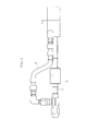
- FIGs. 1 through 4 show a first embodiment.
- a nozzle 1 of the first embodiment is disposed at a secondary cooling zone of a continuous casting equipment to cool slab having a high temperature.
- the nozzle 1 has a liquid inflow path 3 connected to a liquid supply tube 2, an air inflow path 5 connected to an air supply tube 4, and a main fluid flow path 6 having a jet port 6a at its front end.
- the nozzle 1 has an automatic switching valve 7 adopting a spray method (hereinafter referred to as a switching valve 7).
- the switching valve 7 is mounted at a boundary position between the liquid inflow path 3 and the main fluid flow path 6 and between the liquid inflow path 3 and the air inflow path 5.
- the switching valve 7 has a flow path 7a orthogonal to the main fluid flow path 6.
- One end of the flow path 7a is set as a liquid inlet 7b communicating with the liquid inflow path 3.
- the other end of the flow path 7a is set as an air inlet 7c communicating with the air inflow path 5 in such a way that the air inlet 7c confronts the liquid inlet 7b.
- a spring 8 is accommodated inside the flow path 7a of the switching valve 7.
- a valve body 9 for closing the air inlet 7c is disposed at a front end of the spring 8. The air inlet 7c is opened and closed by the valve body 9.
- a valve body is not disposed at the liquid inlet 7b to always open the liquid inlet 7b so that a liquid is always flowed into the flow path 7a.
- a liquid pressure P1 of the liquid and a spring pressure P3 of the spring 8 are always applied to the valve body 9.
- the air supply tube 4 is connected to a compressor 30 to set an air pressure to be always supplied to the air inflow path 5 through the air supply tube 4 to a constant pressure P2.
- the liquid pressure P1 of the liquid is set by a discharge pressure of a pump 31 connected with the liquid supply tube 2.
- the discharge pressure is set according to the kind or temperature of a steel plate cooled by the nozzle to set the flow rate of the liquid.
- the valve body 9 when the liquid pressure P1 is high and P1+P3>P2, the valve body 9 is in the closed state. Thus only the liquid is supplied to the main fluid flow path 6. Therefore spray from the jet port is single fluid spray of spraying only the liquid.
- a spray angle ⁇ in a width direction is comparatively wide and has an angle ⁇ 1.
- the spray angle ⁇ 2 is similar to that in the single fluid spray ( ⁇ 2 ⁇ ⁇ 1), and the flow rate distribution in the thickness direction is uniformly maintained.
- the air is added to the liquid to form the binary fluid.
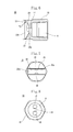
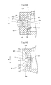
- Figs. 5 through 9 show the second embodiment.
- a nozzle 10 to be used in the second embodiment is different from the nozzle 1 to be used in the first embodiment in the construction of the main fluid flow path 6 at its jet port side.
- the main fluid flow path 6 communicates with the liquid inflow path 3 connected to the liquid supply tube 2 through the switching valve 7 and the air inflow path 5 connected to the air supply tube 4 to switchingly spray single fluid consisting of the liquid and a binary fluid consisting of the mixture of the liquid and the air from the jet port.
- a partitioning wall 19 is formed at a front end of the cylindrical main fluid flow path 6 formed along the center line of a nozzle body 15, namely, along the axis of the nozzle 10.
- Independent holes 17 and 18 are formed at both sides of the partitioning wall 19.
- Front-end closed portions 17a and 18a each having a gradually decreased flow path area are formed at front end portions of the independent holes 17 and 18 respectively.
- a notched portion 22 is concavely formed from the front end of a spray side of the nozzle body 15 to communicate the notched portion 22 with one lateral portion of the front-end closed portion 17a opposed to one lateral portion of the front-end closed portion 18a. Openings of the front-end closed portions 17a and 18a communicating with each other through the notched portion 22 serve as jet ports 20 and 21.
- a bottom surface 22a of the notched portion 22 is formed concavely in the shape of a circular arc in such a way that the bottom surface 22a becomes wider toward the spray side.
- a lateral surface 22b of the notched portion 22 is parallel with the axial direction of the nozzle 10.
- the radius of curvature of the circular arc of the bottom surface 22a is in a range of 4 to 50mm and is determined according to the size of the nozzle body and a requested spray width.
- the bottom surface 22a of the notched portion 22 and the lateral surface 22b thereof are orthogonal to each other in such a way that the jet ports 20 and 21 are sectionally L-shaped.
- U-shaped portions 17b and 18b there are formed U-shaped portions 17b and 18b so configured as to U-turn the fluid to the partitioning wall 19 from the front ends of the independent holes 17 and 18 through the jet ports 20 and 21.
- a tapered portion 23 which becomes wider in an opposite direction is formed continuously with the front end of the spray side of the lateral surface 22b of the notched portion 22.
- the step of spraying the single fluid and the step of spraying the binary fluid when the single fluid consisting of the liquid or the binary fluid consisting of the mixture of the liquid and the air flows into the main fluid flow path 6 are identical to each other and are described below.
- the fluid which has flowed into the main fluid flow path 6 flows into the independent holes 17 and 18 separately.
- the fluid which has flowed into the independent holes 17 and 18 increasing its flow speed with a decrease of the area of the flow paths at the front-end closed portions 17a and 18a, fluids which have flowed out from the opposed jet ports 20 and 21 collide with each other inside the notched portion 22.
- the collision accelerates the diffusion of the fluids in a spray thickness direction T and a spray width direction W.
- the U-shaped portions 17b and 18b so configured as to U-turn the fluid to the partitioning wall 19 from the front ends of the independent holes 17 and 18 through the jet ports 20 and 21.
- a small amount of the fluids jetted from the jet ports 20 and 21 flow in a return direction. Owing to this flow, the fluids are stirred, and the collision between the two flows can be enhanced. Therefore even when the flow rate is low, it is possible to sufficiently secure a spray angle ⁇ n in the spray thickness direction T and a spray angle ⁇ w in the spray width direction W.
- the fluids which have collided with each other are guided by the lateral surface 22b of the notched portion 22 in the spray thickness direction T and smoothly guided by the circular arc-shaped bottom surface 22a of the notched portion 22 in the spray width direction W. Therefore even though the flow rate of the liquid fluctuates, it is possible to provide the stable spray angle ⁇ n in the spray thickness direction T and the stable spray angle ⁇ w in the spray width direction W.
- the fluids can be sprayed at a small energy loss in the spray width direction W.
- the spray in the spray thickness direction T which has been stabilized by the lateral surface 22b of the notched portion 22 is guided by the tapered portion 23 formed continuously with the front end of the spray side of the lateral surface 22b of the notched portion 22 to enlarge the spray angle ⁇ n.
- the bottom surface 22a of the notched portion 22 and the lateral surface 22b thereof are orthogonal to each other in such a way that the jet ports 20 and 21 are sectionally L-shaped. Therefore it is possible to make the openings of the jet ports 20 and 21 large, raise the upper limit value of the flow rate, and make the jet ports 20 and 21 large without changing the size of the nozzle body 15. Therefore it is possible to make the nozzle 10 compact.
- the spray pattern is stable. Thus when the flow rate of the liquid fluctuates, it is possible to lower the ratio of the flow rate of the gas to that of the liquid (air-to-water ratio), restrain the power consumption of the gas supply compressor, and thus save energy.
- the spray pattern is stable. Thus even though the ratio of the flow rate of the gas to that of the liquid (air-to-water ratio) is lowered, it is possible to stably hold the spray angle without fluctuating the spray angle when the nozzle 10 sprays the single fluid consisting of the liquid.
- the fluids which have flowed out from the opposed jet ports of the independent holes collide with each other and diffuse. Thereby it is possible to increase the spray thickness and the spray width. Because the fluids are sprayed under the guidance of the lateral surface of the notched portion and the circular arc-shaped bottom surface thereof, it is possible to obtain a stable spray thickness and spray width and uniformly maintain the flow rate distribution, even though the flow rate fluctuates. Further in the independent holes, the front-end closed portion having the gradually decreased flow path area is formed at the front side of each of the jet ports. Therefore the fluids collide with each other at a high speed and a high pressure, and thus the diffusion effect of the spray can be enhanced.
- the spray pattern is stable.
- the flow rate of the liquid fluctuates and the ratio of the flow rate of the gas to that of the liquid (air-to-water ratio) is lowered, it is possible to use the nozzle 10 without replacing it by switching the spray of the single fluid consisting of the liquid to the spray of the binary fluid consisting of the mixture of the liquid and the air and vice versa.
- the air-to-water ratio can be decreased, it is possible to save the power consumption of the gas supply compressor and save energy.
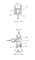
- Fig. 10 shows the third embodiment.
- an electromagnetic switching valve 50 is mounted at the air inlet.
- the electromagnetic switching valve 50 opens so that the nozzle sprays the binary fluid by mixing the air with the liquid.
- the above-described set value of the liquid pressure at which the spray of the single fluid consisting of the liquid is switched to the spray of the binary fluid is in the range of 0.005MPa to 0.9MPa.
- the air-to-water ratio which is the ratio of the amount of the air to a maximum amount of the liquid when the nozzle sprays the binary fluid is set to the range of 0.5 to 5.0.
- Fig. 11 shows the fourth embodiment.
- the air supply tube is laterally confluent with the liquid supply tube provided along the axis of the nozzle.
- a double tube construction is adopted. More specifically, air flows in a central flow path inside an inner tube 40.
- a mixing adaptor 43 accommodating the switching valve 7c having a spring and a valve body is mounted at a front end of the inner tube 40.
- An outer tube 41 is disposed on the outer periphery of the inner tube 40 by interposing a liquid flow path 42 between the outer tube 41 and the inner tube 40.
- a nozzle body 45 is coupled to the front end of the outer tube 41.
- An adaptor (not shown) coupled to an air supply source and a liquid supply source through pipes is coupled to the proximal side of each of the inner tube 40 and the outer tube 41.
- the switching valve 7c is opened to jet the air from an opening 43a disposed at the front end of the mixing adaptor 43 so that the air is mixed in the liquid.
- the mixture of the liquid and the air is sprayed from a jet port 45a disposed at the front end of the nozzle body 45.
- the switching valve 7c When the pressure of the liquid is high, the switching valve 7c remains closed so that the nozzle sprays the single fluid consisting of the liquid.
Landscapes
- Chemical & Material Sciences (AREA)
- Chemical Kinetics & Catalysis (AREA)
- Engineering & Computer Science (AREA)
- Mechanical Engineering (AREA)
- Nozzles (AREA)
- Application Of Or Painting With Fluid Materials (AREA)
- Continuous Casting (AREA)
Claims (2)
- Düse, wobei ein Haupt-Fluidströmungskanal (6), welcher einen Düsenanschluss an seinem vorderen Ende aufweist, mit einem Flüssigkeits-Zuflusskanal (3) in Verbindung steht, welcher mit einem Flüssigkeits-Versorgungsrohr (2) über einen Flüssigkeitseinlass (7b) und mit einem Luft-Einströmkanal (5), welcher mit einem Luftversorgungsrohr (4) über einen Lufteinlass (7c) verbunden ist, verbunden ist, und wobei ein Druck (P1) einer dem Flüssigkeits-Versorgungsrohr (2) zugeführten Flüssigkeit schwankt, wohingegen eine dem LuftVersorgungsrohr (4) zugeführte Druckluft auf einen konstanten Druck eingestellt wird; wobei der Flüssigkeitseinlass (7b) immer geöffnet ist und der Lufteinlass (7c) mit Hilfe eines Schaltventils (7) geöffnet und geschlossen wird;
dadurch gekennzeichnet, dass bei Abnahme eines Drucks (P1) einer von dem Flüssigkeits-Versorgungsrohr (2) zu dem Haupt-Fluidströmungskanal (6) gelieferten Flüssigkeit das Schaltventil (7) geöffnet wird, um Luft in den Haupt-Fluidströmungskanal (6) entsprechend einer Abnahmerate des Drucks der Flüssigkeit einzubringen, so dass die Düse ein binäresfluid sprüht, wobei ausgenommen dann, wenn der Druck der Flüssigkeit abnimmt, die Düse ein einziges aus der Flüssigkeit bestehendes Fluid sprüht; und eine Strömungsrate des gesprühten einzigen Fluids, welches aus der Flüssigkeit besteht, gleich einer Strömungsrate des gesprühten binären Fluids ist, welche durch Addition einer Strömungsrate der Flüssigkeit und einer Strömungsrate der Luft erhalten wird, und ein Sprühwinkel (0) und eine Strömungsraten-Verteilung des einzelnen Fluids, welches von einem an dem vorderen Ende des Haupt-Fluidströmungskanal angeordneten Düsenanschluss gesprüht wird, gleich einem Sprühwinkel und einer Strömungsraten-Verteilung des binären Fluids ist, welches von dem an dem vorderen Ende des Haupt-Fluidströmungspfads (6) angeordneten Düsenanschluss gesprüht wird, wobei der Flüssigkeitseinlass (7b) und der Lufteinlass (7c), welche mit dem Flüssigkeits-Einströmkanal (3) bzw. dem Luft-Einströmkanal (5) in Verbindung stehen, zueinander gegenüber stehen oder an Innen- und Außenpositionen derart, dass der Flüssigkeits-Einströmkanal (3) und der Luft-Einströmkanal (5) parallel zueinander sind. - Düse nach Anspruch 1, wobei ein Ventilkörper des Schaltventils (7) des Lufteinlasses (7c) mittels einer Feder (8) betätigt wird, wobei ein Druck der Luft, welche von dem Lufttversorgungsrohr (4) geliefert wird, auf einen konstanten Druck P2 eingestellt wird, und ein Druck der Feder (8) auf P3 eingestellt wird; wobei dann, wenn der Druck (P1) der von dem Flüssigkeits-Versorgungsrohr (2) gelieferten Flüssigkeit hoch ist und P1+P3>P2 ist, die Düse nur die besagte Flüssigkeit sprüht; und wenn der Flüssigkeitsdruck (P1) niedrig ist und P1+P3<P2 ist, das Schaltventil (7) durch den Luftdruck geöffnet wird, so dass die Düse nur das binäre Fluid sprüht.
Applications Claiming Priority (2)
| Application Number | Priority Date | Filing Date | Title |
|---|---|---|---|
| JP2010063340 | 2010-03-18 | ||
| PCT/JP2010/065586 WO2011114552A1 (ja) | 2010-03-18 | 2010-09-10 | ノズルの噴霧方法およびノズル |
Publications (3)
| Publication Number | Publication Date |
|---|---|
| EP2548652A1 EP2548652A1 (de) | 2013-01-23 |
| EP2548652A4 EP2548652A4 (de) | 2014-06-18 |
| EP2548652B1 true EP2548652B1 (de) | 2015-05-27 |
Family
ID=44648673
Family Applications (1)
| Application Number | Title | Priority Date | Filing Date |
|---|---|---|---|
| EP10847960.1A Active EP2548652B1 (de) | 2010-03-18 | 2010-09-10 | Verfahren zum sprühen mit einer düse sowie düse |
Country Status (3)
| Country | Link |
|---|---|
| EP (1) | EP2548652B1 (de) |
| JP (1) | JP5547802B2 (de) |
| WO (1) | WO2011114552A1 (de) |
Families Citing this family (12)
| Publication number | Priority date | Publication date | Assignee | Title |
|---|---|---|---|---|
| CN103658578A (zh) * | 2013-10-30 | 2014-03-26 | 芜湖新兴铸管有限责任公司 | 一种连铸冷却喷嘴 |
| TWM477195U (zh) * | 2013-11-27 | 2014-05-01 | Zong Jing Investment Inc | 霧化式噴灑器 |
| JP5804131B1 (ja) * | 2014-04-16 | 2015-11-04 | 日油株式会社 | 爆薬の装填装置及びドリルジャンボ |
| KR101642907B1 (ko) * | 2014-12-01 | 2016-08-10 | 주식회사 포스코 | 노즐 및 냉각매체 공급관의 세정방법 |
| CN105509029B (zh) * | 2016-01-25 | 2018-07-27 | 无锡海力自控工程有限公司 | 蒸汽辅助减温器的喷嘴组件 |
| AT520006B1 (de) * | 2017-06-07 | 2021-08-15 | Primetals Technologies Austria GmbH | Kühlmitteldüse zum kühlen eines metallischen strangs in einer stranggussanlage |
| CN109395563B (zh) * | 2018-12-12 | 2023-08-29 | 中国华能集团清洁能源技术研究院有限公司 | 一种高效的液体雾化喷射装置及方法 |
| CN114945414A (zh) * | 2019-12-05 | 2022-08-26 | 泰科消防产品有限合伙公司 | 包含具有多个喷射角度的喷嘴的灭火系统 |
| CN111495625A (zh) * | 2020-04-22 | 2020-08-07 | 郭曼 | 一种流体喷射系统 |
| CN112206960B (zh) * | 2020-09-30 | 2022-04-29 | 苏州乾源涂装有限公司 | 一种防止堵塞且喷涂颗粒更加致密的天然漆喷涂装置 |
| KR20240142555A (ko) * | 2022-11-07 | 2024-09-30 | 시마다 어플리 고도 가이샤 | 중고점도 액체의 도포 방법, 장치 및 노즐 |
| CN118600360B (zh) * | 2024-06-07 | 2025-12-19 | 太原理工大学 | 用于悬浮液等离子喷涂制备柱状晶微结构涂层的送料装置 |
Family Cites Families (4)
| Publication number | Priority date | Publication date | Assignee | Title |
|---|---|---|---|---|
| JPS6295160A (ja) * | 1985-10-22 | 1987-05-01 | Ikeuchi:Kk | スプレ−ノズル |
| JP3414968B2 (ja) * | 1997-02-17 | 2003-06-09 | 株式会社丸山製作所 | オゾン混入装置及び洗浄装置 |
| JP2000312865A (ja) * | 1999-04-28 | 2000-11-14 | Toyota Auto Body Co Ltd | オゾン水洗浄装置 |
| JP2005270870A (ja) * | 2004-03-25 | 2005-10-06 | Fuji Clean:Kk | 高圧オゾン水による洗浄方法及び装置 |
-
2010
- 2010-09-10 WO PCT/JP2010/065586 patent/WO2011114552A1/ja not_active Ceased
- 2010-09-10 JP JP2012505438A patent/JP5547802B2/ja active Active
- 2010-09-10 EP EP10847960.1A patent/EP2548652B1/de active Active
Also Published As
| Publication number | Publication date |
|---|---|
| JP5547802B2 (ja) | 2014-07-16 |
| JPWO2011114552A1 (ja) | 2013-06-27 |
| WO2011114552A1 (ja) | 2011-09-22 |
| EP2548652A1 (de) | 2013-01-23 |
| EP2548652A4 (de) | 2014-06-18 |
Similar Documents
| Publication | Publication Date | Title |
|---|---|---|
| EP2548652B1 (de) | Verfahren zum sprühen mit einer düse sowie düse | |
| EP3162461B1 (de) | Sprühdüse | |
| US8349247B2 (en) | Controlled cooling apparatus and cooling method of steel plate | |
| US9970654B2 (en) | Combustion device for improving turndown ratio | |
| CA2458822A1 (en) | Nozzle and method of jetting fluid onto inner peripheral surface of conduit by the nozzle | |
| EP4429841A1 (de) | Mischdüse für ein laserbearbeitungssystem | |
| US10249888B2 (en) | Passive recirculation device | |
| JP2012125711A (ja) | 気液混合ユニット及び気液噴霧ノズル | |
| CN109417845A (zh) | 用于稳定等离子弧焊炬中的等离子气流的系统及方法 | |
| US5499769A (en) | Fuel injection valve including air promoting atomization | |
| JP2005103367A (ja) | 噴霧ノズル | |
| JP4936904B2 (ja) | 噴射ノズルとそれを用いた噴霧方法 | |
| JP4301776B2 (ja) | ノズル | |
| JP2004016846A (ja) | ノズル | |
| JP4972326B2 (ja) | ノズル | |
| EP4066945A1 (de) | Spritzpistole | |
| RU2410176C2 (ru) | Устройство для контролируемого охлаждения и способ охлаждения стальной плиты | |
| JP2008307460A (ja) | 塗布装置 | |
| CN213040548U (zh) | 减温器系统 | |
| EP3495515A1 (de) | Kühlvorrichtung | |
| CN118454921A (zh) | 雾化喷头以及脱硝喷枪 | |
| JP6866786B2 (ja) | シリンダーバルブ | |
| KR20200061137A (ko) | 냉각수 분사장치 | |
| JP2006055736A (ja) | 液体循環式スプレーガン | |
| KR20180135360A (ko) | 용접용 토치어셈블리 |
Legal Events
| Date | Code | Title | Description |
|---|---|---|---|
| PUAI | Public reference made under article 153(3) epc to a published international application that has entered the european phase |
Free format text: ORIGINAL CODE: 0009012 |
|
| 17P | Request for examination filed |
Effective date: 20121017 |
|
| AK | Designated contracting states |
Kind code of ref document: A1 Designated state(s): AL AT BE BG CH CY CZ DE DK EE ES FI FR GB GR HR HU IE IS IT LI LT LU LV MC MK MT NL NO PL PT RO SE SI SK SM TR |
|
| DAX | Request for extension of the european patent (deleted) | ||
| A4 | Supplementary search report drawn up and despatched |
Effective date: 20140519 |
|
| RIC1 | Information provided on ipc code assigned before grant |
Ipc: B05B 1/12 20060101ALI20140513BHEP Ipc: B22D 11/124 20060101ALI20140513BHEP Ipc: B05B 7/26 20060101AFI20140513BHEP Ipc: B05D 1/02 20060101ALI20140513BHEP |
|
| REG | Reference to a national code |
Ref country code: DE Ref legal event code: R079 Ref document number: 602010024987 Country of ref document: DE Free format text: PREVIOUS MAIN CLASS: B05B0007260000 Ipc: B01F0005040000 |
|
| RIC1 | Information provided on ipc code assigned before grant |
Ipc: B01F 5/04 20060101AFI20140923BHEP Ipc: B05B 7/08 20060101ALI20140923BHEP Ipc: B05B 7/04 20060101ALI20140923BHEP Ipc: B05B 7/12 20060101ALI20140923BHEP Ipc: B01F 3/04 20060101ALI20140923BHEP Ipc: B22D 11/12 20060101ALI20140923BHEP |
|
| GRAP | Despatch of communication of intention to grant a patent |
Free format text: ORIGINAL CODE: EPIDOSNIGR1 |
|
| INTG | Intention to grant announced |
Effective date: 20141121 |
|
| GRAS | Grant fee paid |
Free format text: ORIGINAL CODE: EPIDOSNIGR3 |
|
| GRAA | (expected) grant |
Free format text: ORIGINAL CODE: 0009210 |
|
| AK | Designated contracting states |
Kind code of ref document: B1 Designated state(s): AL AT BE BG CH CY CZ DE DK EE ES FI FR GB GR HR HU IE IS IT LI LT LU LV MC MK MT NL NO PL PT RO SE SI SK SM TR |
|
| REG | Reference to a national code |
Ref country code: GB Ref legal event code: FG4D |
|
| RIN1 | Information on inventor provided before grant (corrected) |
Inventor name: IIMURA, TOMOKATA Inventor name: NAKANO, HISATSUGU |
|
| REG | Reference to a national code |
Ref country code: CH Ref legal event code: EP |
|
| RIN2 | Information on inventor provided after grant (corrected) |
Inventor name: IIMURA, TOMOKATA Inventor name: NAKANO, HISATSUGU |
|
| REG | Reference to a national code |
Ref country code: AT Ref legal event code: REF Ref document number: 728539 Country of ref document: AT Kind code of ref document: T Effective date: 20150615 |
|
| RIN2 | Information on inventor provided after grant (corrected) |
Inventor name: NAKANO, HISATSUGU Inventor name: IIMURA, TOMOTAKA |
|
| REG | Reference to a national code |
Ref country code: NL Ref legal event code: T3 Ref country code: IE Ref legal event code: FG4D |
|
| REG | Reference to a national code |
Ref country code: DE Ref legal event code: R096 Ref document number: 602010024987 Country of ref document: DE Effective date: 20150709 |
|
| REG | Reference to a national code |
Ref country code: AT Ref legal event code: MK05 Ref document number: 728539 Country of ref document: AT Kind code of ref document: T Effective date: 20150527 |
|
| REG | Reference to a national code |
Ref country code: LT Ref legal event code: MG4D |
|
| PG25 | Lapsed in a contracting state [announced via postgrant information from national office to epo] |
Ref country code: ES Free format text: LAPSE BECAUSE OF FAILURE TO SUBMIT A TRANSLATION OF THE DESCRIPTION OR TO PAY THE FEE WITHIN THE PRESCRIBED TIME-LIMIT Effective date: 20150527 Ref country code: NO Free format text: LAPSE BECAUSE OF FAILURE TO SUBMIT A TRANSLATION OF THE DESCRIPTION OR TO PAY THE FEE WITHIN THE PRESCRIBED TIME-LIMIT Effective date: 20150827 Ref country code: FI Free format text: LAPSE BECAUSE OF FAILURE TO SUBMIT A TRANSLATION OF THE DESCRIPTION OR TO PAY THE FEE WITHIN THE PRESCRIBED TIME-LIMIT Effective date: 20150527 Ref country code: HR Free format text: LAPSE BECAUSE OF FAILURE TO SUBMIT A TRANSLATION OF THE DESCRIPTION OR TO PAY THE FEE WITHIN THE PRESCRIBED TIME-LIMIT Effective date: 20150527 Ref country code: LT Free format text: LAPSE BECAUSE OF FAILURE TO SUBMIT A TRANSLATION OF THE DESCRIPTION OR TO PAY THE FEE WITHIN THE PRESCRIBED TIME-LIMIT Effective date: 20150527 Ref country code: PT Free format text: LAPSE BECAUSE OF FAILURE TO SUBMIT A TRANSLATION OF THE DESCRIPTION OR TO PAY THE FEE WITHIN THE PRESCRIBED TIME-LIMIT Effective date: 20150928 |
|
| PG25 | Lapsed in a contracting state [announced via postgrant information from national office to epo] |
Ref country code: BG Free format text: LAPSE BECAUSE OF FAILURE TO SUBMIT A TRANSLATION OF THE DESCRIPTION OR TO PAY THE FEE WITHIN THE PRESCRIBED TIME-LIMIT Effective date: 20150827 Ref country code: LV Free format text: LAPSE BECAUSE OF FAILURE TO SUBMIT A TRANSLATION OF THE DESCRIPTION OR TO PAY THE FEE WITHIN THE PRESCRIBED TIME-LIMIT Effective date: 20150527 Ref country code: AT Free format text: LAPSE BECAUSE OF FAILURE TO SUBMIT A TRANSLATION OF THE DESCRIPTION OR TO PAY THE FEE WITHIN THE PRESCRIBED TIME-LIMIT Effective date: 20150527 Ref country code: GR Free format text: LAPSE BECAUSE OF FAILURE TO SUBMIT A TRANSLATION OF THE DESCRIPTION OR TO PAY THE FEE WITHIN THE PRESCRIBED TIME-LIMIT Effective date: 20150828 Ref country code: IS Free format text: LAPSE BECAUSE OF FAILURE TO SUBMIT A TRANSLATION OF THE DESCRIPTION OR TO PAY THE FEE WITHIN THE PRESCRIBED TIME-LIMIT Effective date: 20150927 |
|
| PG25 | Lapsed in a contracting state [announced via postgrant information from national office to epo] |
Ref country code: DK Free format text: LAPSE BECAUSE OF FAILURE TO SUBMIT A TRANSLATION OF THE DESCRIPTION OR TO PAY THE FEE WITHIN THE PRESCRIBED TIME-LIMIT Effective date: 20150527 Ref country code: EE Free format text: LAPSE BECAUSE OF FAILURE TO SUBMIT A TRANSLATION OF THE DESCRIPTION OR TO PAY THE FEE WITHIN THE PRESCRIBED TIME-LIMIT Effective date: 20150527 |
|
| PG25 | Lapsed in a contracting state [announced via postgrant information from national office to epo] |
Ref country code: RO Free format text: LAPSE BECAUSE OF NON-PAYMENT OF DUE FEES Effective date: 20150527 Ref country code: SK Free format text: LAPSE BECAUSE OF FAILURE TO SUBMIT A TRANSLATION OF THE DESCRIPTION OR TO PAY THE FEE WITHIN THE PRESCRIBED TIME-LIMIT Effective date: 20150527 Ref country code: PL Free format text: LAPSE BECAUSE OF FAILURE TO SUBMIT A TRANSLATION OF THE DESCRIPTION OR TO PAY THE FEE WITHIN THE PRESCRIBED TIME-LIMIT Effective date: 20150527 Ref country code: CZ Free format text: LAPSE BECAUSE OF FAILURE TO SUBMIT A TRANSLATION OF THE DESCRIPTION OR TO PAY THE FEE WITHIN THE PRESCRIBED TIME-LIMIT Effective date: 20150527 |
|
| REG | Reference to a national code |
Ref country code: DE Ref legal event code: R097 Ref document number: 602010024987 Country of ref document: DE |
|
| PLBE | No opposition filed within time limit |
Free format text: ORIGINAL CODE: 0009261 |
|
| STAA | Information on the status of an ep patent application or granted ep patent |
Free format text: STATUS: NO OPPOSITION FILED WITHIN TIME LIMIT |
|
| PG25 | Lapsed in a contracting state [announced via postgrant information from national office to epo] |
Ref country code: MC Free format text: LAPSE BECAUSE OF FAILURE TO SUBMIT A TRANSLATION OF THE DESCRIPTION OR TO PAY THE FEE WITHIN THE PRESCRIBED TIME-LIMIT Effective date: 20150527 Ref country code: LU Free format text: LAPSE BECAUSE OF FAILURE TO SUBMIT A TRANSLATION OF THE DESCRIPTION OR TO PAY THE FEE WITHIN THE PRESCRIBED TIME-LIMIT Effective date: 20150910 |
|
| REG | Reference to a national code |
Ref country code: CH Ref legal event code: PL |
|
| 26N | No opposition filed |
Effective date: 20160301 |
|
| PG25 | Lapsed in a contracting state [announced via postgrant information from national office to epo] |
Ref country code: SI Free format text: LAPSE BECAUSE OF FAILURE TO SUBMIT A TRANSLATION OF THE DESCRIPTION OR TO PAY THE FEE WITHIN THE PRESCRIBED TIME-LIMIT Effective date: 20150527 |
|
| REG | Reference to a national code |
Ref country code: IE Ref legal event code: MM4A |
|
| REG | Reference to a national code |
Ref country code: FR Ref legal event code: ST Effective date: 20160531 |
|
| PG25 | Lapsed in a contracting state [announced via postgrant information from national office to epo] |
Ref country code: CH Free format text: LAPSE BECAUSE OF NON-PAYMENT OF DUE FEES Effective date: 20150930 Ref country code: LI Free format text: LAPSE BECAUSE OF NON-PAYMENT OF DUE FEES Effective date: 20150930 Ref country code: IE Free format text: LAPSE BECAUSE OF NON-PAYMENT OF DUE FEES Effective date: 20150910 |
|
| PG25 | Lapsed in a contracting state [announced via postgrant information from national office to epo] |
Ref country code: FR Free format text: LAPSE BECAUSE OF NON-PAYMENT OF DUE FEES Effective date: 20150930 Ref country code: BE Free format text: LAPSE BECAUSE OF FAILURE TO SUBMIT A TRANSLATION OF THE DESCRIPTION OR TO PAY THE FEE WITHIN THE PRESCRIBED TIME-LIMIT Effective date: 20150527 |
|
| PG25 | Lapsed in a contracting state [announced via postgrant information from national office to epo] |
Ref country code: MT Free format text: LAPSE BECAUSE OF FAILURE TO SUBMIT A TRANSLATION OF THE DESCRIPTION OR TO PAY THE FEE WITHIN THE PRESCRIBED TIME-LIMIT Effective date: 20150527 |
|
| PG25 | Lapsed in a contracting state [announced via postgrant information from national office to epo] |
Ref country code: HU Free format text: LAPSE BECAUSE OF FAILURE TO SUBMIT A TRANSLATION OF THE DESCRIPTION OR TO PAY THE FEE WITHIN THE PRESCRIBED TIME-LIMIT; INVALID AB INITIO Effective date: 20100910 Ref country code: SM Free format text: LAPSE BECAUSE OF FAILURE TO SUBMIT A TRANSLATION OF THE DESCRIPTION OR TO PAY THE FEE WITHIN THE PRESCRIBED TIME-LIMIT Effective date: 20150527 |
|
| PG25 | Lapsed in a contracting state [announced via postgrant information from national office to epo] |
Ref country code: SE Free format text: LAPSE BECAUSE OF FAILURE TO SUBMIT A TRANSLATION OF THE DESCRIPTION OR TO PAY THE FEE WITHIN THE PRESCRIBED TIME-LIMIT Effective date: 20150527 Ref country code: CY Free format text: LAPSE BECAUSE OF FAILURE TO SUBMIT A TRANSLATION OF THE DESCRIPTION OR TO PAY THE FEE WITHIN THE PRESCRIBED TIME-LIMIT Effective date: 20150527 |
|
| PG25 | Lapsed in a contracting state [announced via postgrant information from national office to epo] |
Ref country code: TR Free format text: LAPSE BECAUSE OF FAILURE TO SUBMIT A TRANSLATION OF THE DESCRIPTION OR TO PAY THE FEE WITHIN THE PRESCRIBED TIME-LIMIT Effective date: 20150527 |
|
| PG25 | Lapsed in a contracting state [announced via postgrant information from national office to epo] |
Ref country code: MK Free format text: LAPSE BECAUSE OF FAILURE TO SUBMIT A TRANSLATION OF THE DESCRIPTION OR TO PAY THE FEE WITHIN THE PRESCRIBED TIME-LIMIT Effective date: 20150527 |
|
| PG25 | Lapsed in a contracting state [announced via postgrant information from national office to epo] |
Ref country code: AL Free format text: LAPSE BECAUSE OF FAILURE TO SUBMIT A TRANSLATION OF THE DESCRIPTION OR TO PAY THE FEE WITHIN THE PRESCRIBED TIME-LIMIT Effective date: 20150527 |
|
| REG | Reference to a national code |
Ref country code: DE Ref legal event code: R079 Ref document number: 602010024987 Country of ref document: DE Free format text: PREVIOUS MAIN CLASS: B01F0005040000 Ipc: B01F0025300000 |
|
| P01 | Opt-out of the competence of the unified patent court (upc) registered |
Effective date: 20230509 |
|
| PGFP | Annual fee paid to national office [announced via postgrant information from national office to epo] |
Ref country code: NL Payment date: 20250814 Year of fee payment: 16 |
|
| PGFP | Annual fee paid to national office [announced via postgrant information from national office to epo] |
Ref country code: DE Payment date: 20250730 Year of fee payment: 16 |
|
| PGFP | Annual fee paid to national office [announced via postgrant information from national office to epo] |
Ref country code: IT Payment date: 20250825 Year of fee payment: 16 |
|
| PGFP | Annual fee paid to national office [announced via postgrant information from national office to epo] |
Ref country code: GB Payment date: 20250731 Year of fee payment: 16 |