EP2548773A2 - Dispositif d'essuyage - Google Patents
Dispositif d'essuyage Download PDFInfo
- Publication number
- EP2548773A2 EP2548773A2 EP12175322A EP12175322A EP2548773A2 EP 2548773 A2 EP2548773 A2 EP 2548773A2 EP 12175322 A EP12175322 A EP 12175322A EP 12175322 A EP12175322 A EP 12175322A EP 2548773 A2 EP2548773 A2 EP 2548773A2
- Authority
- EP
- European Patent Office
- Prior art keywords
- adapter
- positive
- locking element
- wiper
- positive locking
- Prior art date
- Legal status (The legal status is an assumption and is not a legal conclusion. Google has not performed a legal analysis and makes no representation as to the accuracy of the status listed.)
- Granted
Links
Images

Classifications
-
- B—PERFORMING OPERATIONS; TRANSPORTING
- B60—VEHICLES IN GENERAL
- B60S—SERVICING, CLEANING, REPAIRING, SUPPORTING, LIFTING, OR MANOEUVRING OF VEHICLES, NOT OTHERWISE PROVIDED FOR
- B60S1/00—Cleaning of vehicles
- B60S1/02—Cleaning windscreens, windows or optical devices
- B60S1/04—Wipers or the like, e.g. scrapers
- B60S1/32—Wipers or the like, e.g. scrapers characterised by constructional features of wiper blade arms or blades
- B60S1/38—Wiper blades
- B60S1/3848—Flat-type wiper blade, i.e. without harness
- B60S1/3849—Connectors therefor; Connection to wiper arm; Attached to blade
- B60S1/387—Connectors therefor; Connection to wiper arm; Attached to blade the connector being suitable for receiving different types of adapter
-
- B—PERFORMING OPERATIONS; TRANSPORTING
- B60—VEHICLES IN GENERAL
- B60S—SERVICING, CLEANING, REPAIRING, SUPPORTING, LIFTING, OR MANOEUVRING OF VEHICLES, NOT OTHERWISE PROVIDED FOR
- B60S1/00—Cleaning of vehicles
- B60S1/02—Cleaning windscreens, windows or optical devices
- B60S1/04—Wipers or the like, e.g. scrapers
- B60S1/32—Wipers or the like, e.g. scrapers characterised by constructional features of wiper blade arms or blades
- B60S1/38—Wiper blades
- B60S1/3848—Flat-type wiper blade, i.e. without harness
- B60S1/3849—Connectors therefor; Connection to wiper arm; Attached to blade
- B60S1/3851—Mounting of connector to blade assembly
- B60S1/3858—Mounting of connector to blade assembly with protrusions cooperating with holes
-
- B—PERFORMING OPERATIONS; TRANSPORTING
- B60—VEHICLES IN GENERAL
- B60S—SERVICING, CLEANING, REPAIRING, SUPPORTING, LIFTING, OR MANOEUVRING OF VEHICLES, NOT OTHERWISE PROVIDED FOR
- B60S1/00—Cleaning of vehicles
- B60S1/02—Cleaning windscreens, windows or optical devices
- B60S1/04—Wipers or the like, e.g. scrapers
- B60S1/32—Wipers or the like, e.g. scrapers characterised by constructional features of wiper blade arms or blades
- B60S1/38—Wiper blades
- B60S1/3806—Means, or measures taken, for influencing the aerodynamic quality of the wiper blades
- B60S1/381—Spoilers mounted on the squeegee or on the vertebra
-
- B—PERFORMING OPERATIONS; TRANSPORTING
- B60—VEHICLES IN GENERAL
- B60S—SERVICING, CLEANING, REPAIRING, SUPPORTING, LIFTING, OR MANOEUVRING OF VEHICLES, NOT OTHERWISE PROVIDED FOR
- B60S1/00—Cleaning of vehicles
- B60S1/02—Cleaning windscreens, windows or optical devices
- B60S1/04—Wipers or the like, e.g. scrapers
- B60S1/32—Wipers or the like, e.g. scrapers characterised by constructional features of wiper blade arms or blades
- B60S1/38—Wiper blades
- B60S1/3848—Flat-type wiper blade, i.e. without harness
- B60S1/3874—Flat-type wiper blade, i.e. without harness with a reinforcing vertebra
- B60S1/3875—Flat-type wiper blade, i.e. without harness with a reinforcing vertebra rectangular section
- B60S1/3879—Flat-type wiper blade, i.e. without harness with a reinforcing vertebra rectangular section placed in side grooves in the squeegee
-
- B—PERFORMING OPERATIONS; TRANSPORTING
- B60—VEHICLES IN GENERAL
- B60S—SERVICING, CLEANING, REPAIRING, SUPPORTING, LIFTING, OR MANOEUVRING OF VEHICLES, NOT OTHERWISE PROVIDED FOR
- B60S1/00—Cleaning of vehicles
- B60S1/02—Cleaning windscreens, windows or optical devices
- B60S1/04—Wipers or the like, e.g. scrapers
- B60S1/32—Wipers or the like, e.g. scrapers characterised by constructional features of wiper blade arms or blades
- B60S1/38—Wiper blades
- B60S2001/3827—Wiper blades characterised by the squeegee or blade rubber or wiping element
- B60S2001/3836—Wiper blades characterised by the squeegee or blade rubber or wiping element characterised by cross-sectional shape
Definitions
- the invention relates to a wiper device with an adapter which forms an articulation point to a wiper arm or a wiper blade and has at least one positive locking element which is provided for positive connection with at least one positive locking element of another adapter.
- the wiper device has at least one blocking element which is provided for producing the positive connection between the at least one positive locking element of the adapter and the at least one positive locking element of the further adapter to deflect the at least one positive locking element of the adapter.
- An “adapter” is to be understood in particular as a wiper arm adapter or a wiper blade adapter.
- a “wiper arm adapter” is to be understood in this context in particular as an adapter which has a contact region to a wiper arm component and is intended to provide a coupling region of the wiper arm component for a coupling and / or contacting with a wiper blade adapter.
- the Wischarmbauteil can be attached to a wiper arm.
- a wiper blade adapter in particular an adapter can be understood that has a contact region to a wiper blade component and is captively connected to the wiper blade component, in a disassembled state of a wiper blade by a wiper arm, at least in an operating state and is intended to provide a coupling region of the wiper blade component for a coupling and / or to provide contact with a wiper arm adapter.
- an adapter can be understood that has a contact region to a wiper blade component and is captively connected to the wiper blade component, in a disassembled state of a wiper blade by a wiper arm, at least in an operating state and is intended to provide a coupling region of the wiper blade component for a coupling and / or to provide contact with a wiper arm adapter.
- intended is intended to be understood in particular specially designed and / or equipped.
- the adapter is designed as a Wischarmadapter.
- the form-fitting connection between the adapter formed as a wiper arm adapter and the further adapter can be configured particularly advantageously.
- the blocking element is provided for deflecting the at least one positive-locking element of the adapter from its original state.
- the adapter can be mounted and dismantled particularly advantageous.
- a "state of origin” is understood in particular to mean a state of the at least one positive-locking element into which it exits without a force acting from outside on the positive-locking element.
- the blocking element is designed as a separate component.
- the blocking element can be made particularly simple.
- formed as a separate component is to be understood in particular that the blocking element is designed as a separate closed component, so that this is at least detachably formed by the wiper blade adapter or Wischarmadapter and in particular differs from a configuration in which the locking element in one piece is formed with the wiper blade adapter or Wischarmadapter.
- one-piece should in particular be cohesively connected, as for example by a welding process and / or bonding process, etc., and particularly advantageous molded, as understood by the production of a cast and / or by the production in a single or Mehrkomponentenspritzmaschine.
- the blocking element is provided for a tool-free assembly.
- the blocking element can be advantageous to the user easy to be mounted.
- a "tool-free assembly” is to be understood in particular a manual assembly, which can perform a user in particular without the aid of a tool.
- the adapter has at least one further form-fitting element which is intended to transmit at least a substantial part of a wiping force.
- a “wiping force” is to be understood in particular a force that is generated by a drive motor and is transmitted via the wiper arm to the wiper blade.
- the further form-locking element transmits at least 40%, preferably at least 70% and particularly preferably at least 90% of the wiping force, wherein the part which transmits a single further form-locking element, is dependent on a number of other positive locking elements.
- the at least one further form-fitting element of the adapter is designed as a pin.
- a "pin” is to be understood in particular a survey whose maximum transverse extent is at most as large as their extent along their main extension direction.
- the form-fitting element of the wiper arm adapter has an oval basic shape.
- a “basic form” is to be understood, in particular, as meaning a shape of the positive-locking element, viewed in the main extension direction of the positive-locking element.
- FIG. 1 shows an exploded view of a system according to the invention with a wiper device of a motor vehicle.
- the wiper device has an adapter 10, which has a non-illustrated articulation point to a wiper arm.
- the adapter 10, which has the point of articulation with the wiper arm is designed as a wiper arm adapter.
- the adapter 10 designed as a wiper arm adapter must be replaced.
- Embodiments of said articulation point of the adapter 10 are generally known to the person skilled in the art and are not shown for reasons of clarity.
- the system comprises a further adapter 20 and a wiper blade 12.
- the further adapter 20 has an articulation point 28 for the wiper blade 12.
- the further adapter 20, which has the articulation point 28 for the wiper blade 12, is designed as a wiper blade adapter.
- the designed as a wiper arm adapter 10 is detachable from the wiper blade designed as a further adapter 20 and thus formed interchangeable.
- the trained as a wiper blade adapter further adapter 20 has a main body 30.
- the base body 30 is formed by a plastic injection molded part. It is also conceivable in this context to form the main body 30 from a metal part, such as, in particular, from a metal sheet, or from another material that appears appropriate to the person skilled in the art.
- the main body 30 includes a flat support surface 32.
- the support surface 32 is used in a mounting operation as a system for the trained as Wischarmadapter adapter 10.
- the adapter 10 is placed on the support surface 32 in a mounting operation.
- a vertical axis 34 is arranged perpendicular to the bearing surface 32 of the adapter 20 designed as a wiper blade adapter.
- the vertical axis 34 is arranged parallel to a main pressing force 36 of the adapter 10 designed as a wiper arm adapter.
- the Hauptanpresskraft 36 is generated by a force acting on the wiper arm torque and presses the wiper blade adapter formed as another adapter 20 and connected to the other adapter 20 articulated wiper blade 12 in the direction of a not-to-be-described motor vehicle window.
- a horizontal axis is arranged parallel to a main extension direction of the wiper blade 12.
- the adapter 10 For form-fitting connection of the adapter 10 and the further adapter 20 of the trained as a wiper arm adapter 10 forms two form-locking elements 14, 16 from.
- the adapter 10 has a recess 38.
- the recess 38 is arranged on a side of the adapter 10 facing the further adapter 20 in an assembled state.
- the recess 38 is centrally introduced into the adapter 10 along the horizontal axis.
- the interlocking elements 14, 16 are formed as hooks and have their main extension direction along the vertical axis 34.
- the hook-shaped positive locking elements 14, 16 are arranged in the recess 38.
- the interlocking elements 14, 16 are spaced from each other and each have an equal distance from a median plane of the recess 38.
- a hook shape 40, 42 of the form-fitting elements 14, 16 is directed along the main extension direction in each case by the other form-fitting element 14, 16 away.
- the form-fitting elements 14, 16 stand with their hook shape 40, 42 each have a lower contact surface 44 of the adapter 10 also.
- the form-fitting elements 14, 16 divide the recess 38 into three areas.
- a middle region between the two form-fitting elements 14, 16 is formed as a blocking element receptacle 46.
- the areas between one of the form-locking elements 14, 16 and an adjacent wall 48, 50 of the recess 38 are each formed as a deflection zone 52, 54. In an original state are the Positive locking elements 14, 16 slightly inward, so bent against each other.
- the deflection zones 52, 54 the form-locking elements 14, 16 designed as hooks can be bent outward.
- the adapter 10 has two further positive-locking elements 24, 26.
- the further form-fitting elements 24, 26 are intended to transmit a substantial part of a wiping force.
- the further form-fitting elements 24, 26 are formed as pins.
- the form-fitting elements 24, 26 have an oval basic shape, whereby a wiping force of the wiper arm can be transmitted particularly well by the adapters 10, 20.
- the form-locking elements 24, 26 designed as pins are arranged on the lower contact surface 44 of the adapter 10. In each case one of the positive locking elements 24, 26 is arranged along the horizontal axis in an outer region of the adapter 10.
- the form-fitting elements 24, 26 each have an equal distance from a median plane of the adapter 10.
- a fit that can be made via the interlocking elements 24, 26 is open along the vertical axis 34 in one direction. In this direction, there is also a separation of the adapters 10, 20 from each other.
- the adapter 10, 20 are connected captively to each other and thus also the essential transmission of the wiping force provided positive-locking elements 24, 26 held and fixed in their positive connection.
- the further adapter 20 also has a form-locking element 18.
- the form-locking element 18 is provided for the positive connection with the form-locking elements 14, 16 of the adapter 10 designed as a wiper arm adapter.
- the form-fitting element 18 of the further adapter 20 is formed corresponding to the two form-locking elements 14, 16 of the adapter 10.
- the form-fitting element 18 is formed as a recess, each having an undercut 56, 58 at the orthogonal to the horizontal axis aligned ends.
- the undercuts 56, 58 are provided to be positively connected in a mounted state with the hook shapes 40, 42 of the form-locking elements 14, 16 of the adapter 10 designed as hooks.
- a width of the form-locking element 18 designed as a recess is just as large along the horizontal axis that both form-fit elements 14, 16 of the adapter 10, without leaving their original state to be deflected, can be introduced into the recess formed as a form-locking element 18.
- the form-locking element 18 designed as a recess is designed so that the form-locking elements 14, 16 of the adapter 10 are slightly bent during assembly.
- the further adapter 20 For receiving the two further form-fitting elements 24, 26 of the adapter 10, the further adapter 20 also has two further form-fitting elements 60, 62.
- the interlocking elements 60, 62 are formed corresponding to the further interlocking elements 24, 26 of the adapter 10 designed as a wiper arm adapter.
- the positive locking elements 60, 62 are formed as recesses, which have an oval basic shape.
- the form-locking elements 60, 62 formed as recesses are introduced into the bearing surface 32 of the main body 30.
- the form-locking elements 24, 26 in the form of a wiper arm adapter 10 are arranged in the form-locking elements 60, 62 of the adapter 20 designed as a wiper blade adapter.
- the wiper device has a blocking element 22.
- the blocking element 22 has a blocking region 64 and a handle 66.
- the blocking element 22 is provided for a tool-free assembly.
- the locking element 22 can be mounted by an operator tool-free by hand.
- the blocking element 22 is intended to deflect the interlocking elements 14, 16 of the adapter 10 designed as a wiper arm adapter.
- the blocking element 22 is pushed during assembly with the blocking region 64 into the blocking element receptacle 46 of the adapter 10 designed as a wiper arm adapter.
- the blocking region 64 of the blocking element 22 has a tapering contour at its end facing away from the handle 66, whereby the blocking element 22 can be pushed more easily into the blocking element receptacle 46 during assembly.
- the blocking element 22 By inserting the blocking element 22 into the blocking element receptacle 46, the positive-fit elements 14, 16 of the adapter 10 are spread and deflected out of their original state.
- the hook forms 40, 42 of the form-locking elements 14, 16 are pressed behind the undercuts 56, 58 of the form-fitting element 18, whereby a positive connection is formed.
- the blocking element 22 has a detent element, which is not shown in more detail, for captive protection, by means of which the blocking element 22 can be permanently mounted in the blocking element receptacle 46.
- the blocking element 22 is arranged captively in the blocking element receptacle 46 only by a spring force, which exert the positive-locking elements 14, 16 of the adapter 10 on the blocking element 22.
- the blocking element 22 can be pushed by means of a tool into the blocking element receptacle 46.
- the blocking element 22 could, for example, have a receptacle via which the blocking element 22 can be picked up by means of a normal key or another tool that appears appropriate to a person skilled in the art, such as by means of a wrench, and then pushed into the blocking element receptacle 46 by means of the tool.
- a wind deflector element 68 On the wiper device, a wind deflector element 68, a carrier element 70 and the wiper blade 12 are arranged.
- the wind deflector element 68 has two symmetrically formed, concave wind deflector surfaces 72 which deflect the wind occurring in an operating state and thereby increase the main contact pressure 36.
- the Windabweiserelement 68 is divided into two, that is formed by two separate components.
- the carrier element 70 comprises two spring rails 74. However, in this connection it is also conceivable to use a one-piece spring rail as the carrier element.
- the carrier element 70 is inserted during assembly into a longitudinal guide rail 76 of the wind deflector element 68.
- the wiper blade 12 is held by the spring rails 74 on both sides.
- the wiper blade 12 has on each side a receiving groove 78 for the carrier element 70.
- Two end caps 80, 82 close off the carrier element 70 at one end in a longitudinal direction of the wiper blade 12 and avoid detaching the spring rails 74 from the receiving groove 78.
- the wiper blade 12 is thus connected to the wind deflector element 68 via the carrier element 70 in an assembled state ,
- the carrier element 70 has four fastening lugs 84, 86. In each case two fastening lugs 84 point in a direction which runs opposite to a direction of the other two fastening lugs 86.
- the main body 30 of the wiper blade adapter formed as another adapter 20 has four mounting recesses 88, which correspond with the mounting lugs 84, 86 in shape. For mounting the wiper blade adapter formed as a further adapter 20 with the support member 70, the mounting lugs 84, 86 are inserted into the mounting recesses 88.
- the expert appears useful mounting methods for mounting the support member 70 with the wiper blade adapter designed as another adapter 20 conceivable, such as in particular a suspension of a support member in a guide rail of the wiper blade adapter formed as further adapter 20. Further, enclosing the body 30 conceivable by a support element. Furthermore, it is also conceivable to glue the carrier element 70 to the main body 30, to screw and / or to rivet. If the main body 30 of the wiper blade adapter designed as a further adapter 20 formed by a metal part, a connection of a support member can also be effected by a welded or soldered connection.
- FIG. 2 shows a perspective view of the wiper device before a mounting operation.
- the wind deflector element 68, the carrier element 70 and the wiper blade 12 are connected captively to the adapter 20 formed as a wiper blade adapter.
- the trained as a wiper arm adapter 10 is not yet connected to the designed as a wiper blade adapter adapter 20.
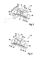
- FIG. 3 shows a perspective view of the wiper device after a first assembly step.
- the positive-locking elements 14, 16 of the adapter 10 formed as a wiper arm adapter are pushed into the form-locking element 18 of the adapter 20 designed as a wiper blade adapter.
- the other form-fitting elements 24, 26 of the adapter 10 are arranged in the correspondingly formed positive-locking elements 60, 62 of the further adapter 20.
- the adapter 10 lies with its contact surface 44 on the support surface 32 of the base body 30 of the adapter 20.
- the blocking element 22 has not yet been mounted, and thus there is no positive connection between the positive-locking elements 14, 16 of the adapter 10 and the positive-locking element 18 of the further adapter 20.
- FIG. 4 shows the wiper in an assembled state.
- the blocking element 22 is pushed into the blocking element receptacle 46, as a result of which the blocking element 22 has deflected the hook shapes 40, 42 of the form-fitting elements 14, 16 of the adapter 10 formed as a wiper arm adapter behind the undercuts 56, 58 of the form-locking element 18 of the adapter 20 designed as a wiper blade adapter , As a result, the adapter 10 is captively connected to the other adapter 20.
- the form-fitting elements 14, 16 are formed by the further, designed as a wiper blade adapter adapter 20 and the positive locking element 18 of the wiper arm adapter formed as 10. Further, it is also conceivable that formed as a pin form-fit elements 24, 26 of the wiper blade adapter designed as an adapter 20 and formed as a recess corresponding interlocking elements 60, 62 are formed by the designed as a wiper arm adapter 10.
Landscapes
- Engineering & Computer Science (AREA)
- Mechanical Engineering (AREA)
- Cleaning Implements For Floors, Carpets, Furniture, Walls, And The Like (AREA)
- Pivots And Pivotal Connections (AREA)
Applications Claiming Priority (1)
| Application Number | Priority Date | Filing Date | Title |
|---|---|---|---|
| DE102011079535A DE102011079535A1 (de) | 2011-07-21 | 2011-07-21 | Wischvorrichtung |
Publications (3)
| Publication Number | Publication Date |
|---|---|
| EP2548773A2 true EP2548773A2 (fr) | 2013-01-23 |
| EP2548773A3 EP2548773A3 (fr) | 2018-04-04 |
| EP2548773B1 EP2548773B1 (fr) | 2019-06-19 |
Family
ID=46466270
Family Applications (1)
| Application Number | Title | Priority Date | Filing Date |
|---|---|---|---|
| EP12175322.2A Active EP2548773B1 (fr) | 2011-07-21 | 2012-07-06 | Dispositif d'essuyage et procédé d'assemblage d'un dispositif d'essuyage |
Country Status (3)
| Country | Link |
|---|---|
| EP (1) | EP2548773B1 (fr) |
| DE (1) | DE102011079535A1 (fr) |
| ES (1) | ES2746197T3 (fr) |
Cited By (1)
| Publication number | Priority date | Publication date | Assignee | Title |
|---|---|---|---|---|
| CN106515669A (zh) * | 2015-09-11 | 2017-03-22 | 罗伯特·博世有限公司 | 雨刷片装置 |
Family Cites Families (4)
| Publication number | Priority date | Publication date | Assignee | Title |
|---|---|---|---|---|
| FR2830823B1 (fr) * | 2001-10-15 | 2004-02-27 | Valeo Systemes Dessuyage | Essuie-glace de vehicule automobile comportant un fermoir de securite |
| FR2893896B1 (fr) * | 2005-11-30 | 2008-02-01 | Valeo Systemes Dessuyage | Support de montage d'un balai d'essuie-glace sur un bras d'entrainement realise en tole pliee |
| WO2010016000A1 (fr) * | 2008-08-05 | 2010-02-11 | Teklas Kaucuk Sanayi Ve Ticaret A.S. | Essuie-glace de pare-brise |
| CN201313541Y (zh) * | 2008-12-03 | 2009-09-23 | 东风汽车有限公司 | 一种雨刮器 |
-
2011
- 2011-07-21 DE DE102011079535A patent/DE102011079535A1/de not_active Ceased
-
2012
- 2012-07-06 EP EP12175322.2A patent/EP2548773B1/fr active Active
- 2012-07-06 ES ES12175322T patent/ES2746197T3/es active Active
Non-Patent Citations (1)
| Title |
|---|
| None |
Cited By (1)
| Publication number | Priority date | Publication date | Assignee | Title |
|---|---|---|---|---|
| CN106515669A (zh) * | 2015-09-11 | 2017-03-22 | 罗伯特·博世有限公司 | 雨刷片装置 |
Also Published As
| Publication number | Publication date |
|---|---|
| EP2548773B1 (fr) | 2019-06-19 |
| ES2746197T3 (es) | 2020-03-05 |
| DE102011079535A1 (de) | 2013-01-24 |
| EP2548773A3 (fr) | 2018-04-04 |
Similar Documents
| Publication | Publication Date | Title |
|---|---|---|
| DE60120717T2 (de) | Scheibenwischervorrichtung aufweisend ein Trägerelement und ein Wischblatt | |
| EP0923471B1 (fr) | Raclette d'essuie-glace pour le nettoyage de vitres de vehicules | |
| EP1337419B1 (fr) | Dispositif de fixation liberable d'un essuie-glace pour le nettoyage de vitres, en particulier de vehicules a moteur, sur un bras d'essuie-glace | |
| EP2734419B1 (fr) | Système d'essuie-glace | |
| EP3233591B1 (fr) | Dispositif d'adaptation | |
| EP2861467B1 (fr) | Système adaptateur de balai d'essuie-glace | |
| DE10108200A1 (de) | Wischvorrichtung insbesondere für Scheiben von Kraftfahrzeugen | |
| EP1117576A1 (fr) | Dispositif d'essuie-glace pour vitres d'automobiles comportant un bras d'essuie-glace sollicite en direction de la vitre et depla able entre des positions reversibles | |
| EP1163132A1 (fr) | Dispositif essuie-glace pour vehicules automobiles | |
| EP1056628A1 (fr) | Dispositif pour l'assemblage articule d'une raclette d'essuie-glace destinee aux vitres de vehicules automobiles avec un bras d'essuie-glace, et procede de realisation de cet assemblage | |
| DE102012106944A1 (de) | Wischblatt zum Reinigen von Fahrzeugscheiben | |
| WO2007071487A1 (fr) | Element de raccordement | |
| EP2651711A1 (fr) | Système de balai d'essuie-glace | |
| EP2726338A1 (fr) | Dispositif balai d'essuie-glace | |
| DE102011053089A1 (de) | Wischblatt für eine Wischeinrichtung eines Kraftfahrzeugs und Wischeinrichtung | |
| EP2861469B1 (fr) | Système adaptateur de balai d'essuie-glace | |
| DE102014114688A1 (de) | Wischblatt und Wischvorrichtung zum Reinigen von Fahrzeugscheiben | |
| DE102012209956A1 (de) | Wischblattadaptersystem | |
| DE102005010678A1 (de) | Vorrichtung zur Befestigung eines Rundschaftmeißels | |
| EP2548773B1 (fr) | Dispositif d'essuyage et procédé d'assemblage d'un dispositif d'essuyage | |
| EP2861470B1 (fr) | Système adaptateur de balai d'essuie-glace | |
| DE102010047098A1 (de) | Wischblatt zum Reinigen von Fahrzeugscheiben und Wischarm mit einem Wischblatt | |
| EP2651709B1 (fr) | Dispositif de balai essuie glace | |
| EP2734420B1 (fr) | Système adaptateur de balai d'essuie-glace | |
| DE10346653A1 (de) | Kettenlasche, Kettenglied und Energieführungskette, sowie Zwischenstück für eine Energieführungskette, mit torsionsgekoppelten Verriegelungsmitteln zum Verbinden von Quersteg und Kettenlasche |
Legal Events
| Date | Code | Title | Description |
|---|---|---|---|
| PUAI | Public reference made under article 153(3) epc to a published international application that has entered the european phase |
Free format text: ORIGINAL CODE: 0009012 |
|
| AK | Designated contracting states |
Kind code of ref document: A2 Designated state(s): AL AT BE BG CH CY CZ DE DK EE ES FI FR GB GR HR HU IE IS IT LI LT LU LV MC MK MT NL NO PL PT RO RS SE SI SK SM TR |
|
| AX | Request for extension of the european patent |
Extension state: BA ME |
|
| PUAL | Search report despatched |
Free format text: ORIGINAL CODE: 0009013 |
|
| AK | Designated contracting states |
Kind code of ref document: A3 Designated state(s): AL AT BE BG CH CY CZ DE DK EE ES FI FR GB GR HR HU IE IS IT LI LT LU LV MC MK MT NL NO PL PT RO RS SE SI SK SM TR |
|
| AX | Request for extension of the european patent |
Extension state: BA ME |
|
| RIC1 | Information provided on ipc code assigned before grant |
Ipc: B60S 1/38 20060101AFI20180227BHEP |
|
| STAA | Information on the status of an ep patent application or granted ep patent |
Free format text: STATUS: REQUEST FOR EXAMINATION WAS MADE |
|
| 17P | Request for examination filed |
Effective date: 20181004 |
|
| RBV | Designated contracting states (corrected) |
Designated state(s): AL AT BE BG CH CY CZ DE DK EE ES FI FR GB GR HR HU IE IS IT LI LT LU LV MC MK MT NL NO PL PT RO RS SE SI SK SM TR |
|
| GRAP | Despatch of communication of intention to grant a patent |
Free format text: ORIGINAL CODE: EPIDOSNIGR1 |
|
| STAA | Information on the status of an ep patent application or granted ep patent |
Free format text: STATUS: GRANT OF PATENT IS INTENDED |
|
| INTG | Intention to grant announced |
Effective date: 20190117 |
|
| GRAS | Grant fee paid |
Free format text: ORIGINAL CODE: EPIDOSNIGR3 |
|
| GRAA | (expected) grant |
Free format text: ORIGINAL CODE: 0009210 |
|
| STAA | Information on the status of an ep patent application or granted ep patent |
Free format text: STATUS: THE PATENT HAS BEEN GRANTED |
|
| AK | Designated contracting states |
Kind code of ref document: B1 Designated state(s): AL AT BE BG CH CY CZ DE DK EE ES FI FR GB GR HR HU IE IS IT LI LT LU LV MC MK MT NL NO PL PT RO RS SE SI SK SM TR |
|
| REG | Reference to a national code |
Ref country code: GB Ref legal event code: FG4D Free format text: NOT ENGLISH |
|
| REG | Reference to a national code |
Ref country code: CH Ref legal event code: EP |
|
| REG | Reference to a national code |
Ref country code: IE Ref legal event code: FG4D Free format text: LANGUAGE OF EP DOCUMENT: GERMAN |
|
| REG | Reference to a national code |
Ref country code: DE Ref legal event code: R096 Ref document number: 502012014925 Country of ref document: DE |
|
| REG | Reference to a national code |
Ref country code: AT Ref legal event code: REF Ref document number: 1145086 Country of ref document: AT Kind code of ref document: T Effective date: 20190715 |
|
| REG | Reference to a national code |
Ref country code: NL Ref legal event code: MP Effective date: 20190619 |
|
| PG25 | Lapsed in a contracting state [announced via postgrant information from national office to epo] |
Ref country code: FI Free format text: LAPSE BECAUSE OF FAILURE TO SUBMIT A TRANSLATION OF THE DESCRIPTION OR TO PAY THE FEE WITHIN THE PRESCRIBED TIME-LIMIT Effective date: 20190619 Ref country code: NO Free format text: LAPSE BECAUSE OF FAILURE TO SUBMIT A TRANSLATION OF THE DESCRIPTION OR TO PAY THE FEE WITHIN THE PRESCRIBED TIME-LIMIT Effective date: 20190919 Ref country code: AL Free format text: LAPSE BECAUSE OF FAILURE TO SUBMIT A TRANSLATION OF THE DESCRIPTION OR TO PAY THE FEE WITHIN THE PRESCRIBED TIME-LIMIT Effective date: 20190619 Ref country code: SE Free format text: LAPSE BECAUSE OF FAILURE TO SUBMIT A TRANSLATION OF THE DESCRIPTION OR TO PAY THE FEE WITHIN THE PRESCRIBED TIME-LIMIT Effective date: 20190619 Ref country code: LT Free format text: LAPSE BECAUSE OF FAILURE TO SUBMIT A TRANSLATION OF THE DESCRIPTION OR TO PAY THE FEE WITHIN THE PRESCRIBED TIME-LIMIT Effective date: 20190619 Ref country code: HR Free format text: LAPSE BECAUSE OF FAILURE TO SUBMIT A TRANSLATION OF THE DESCRIPTION OR TO PAY THE FEE WITHIN THE PRESCRIBED TIME-LIMIT Effective date: 20190619 |
|
| REG | Reference to a national code |
Ref country code: LT Ref legal event code: MG4D |
|
| PG25 | Lapsed in a contracting state [announced via postgrant information from national office to epo] |
Ref country code: GR Free format text: LAPSE BECAUSE OF FAILURE TO SUBMIT A TRANSLATION OF THE DESCRIPTION OR TO PAY THE FEE WITHIN THE PRESCRIBED TIME-LIMIT Effective date: 20190920 Ref country code: RS Free format text: LAPSE BECAUSE OF FAILURE TO SUBMIT A TRANSLATION OF THE DESCRIPTION OR TO PAY THE FEE WITHIN THE PRESCRIBED TIME-LIMIT Effective date: 20190619 Ref country code: LV Free format text: LAPSE BECAUSE OF FAILURE TO SUBMIT A TRANSLATION OF THE DESCRIPTION OR TO PAY THE FEE WITHIN THE PRESCRIBED TIME-LIMIT Effective date: 20190619 Ref country code: BG Free format text: LAPSE BECAUSE OF FAILURE TO SUBMIT A TRANSLATION OF THE DESCRIPTION OR TO PAY THE FEE WITHIN THE PRESCRIBED TIME-LIMIT Effective date: 20190919 |
|
| PG25 | Lapsed in a contracting state [announced via postgrant information from national office to epo] |
Ref country code: RO Free format text: LAPSE BECAUSE OF FAILURE TO SUBMIT A TRANSLATION OF THE DESCRIPTION OR TO PAY THE FEE WITHIN THE PRESCRIBED TIME-LIMIT Effective date: 20190619 Ref country code: CZ Free format text: LAPSE BECAUSE OF FAILURE TO SUBMIT A TRANSLATION OF THE DESCRIPTION OR TO PAY THE FEE WITHIN THE PRESCRIBED TIME-LIMIT Effective date: 20190619 Ref country code: EE Free format text: LAPSE BECAUSE OF FAILURE TO SUBMIT A TRANSLATION OF THE DESCRIPTION OR TO PAY THE FEE WITHIN THE PRESCRIBED TIME-LIMIT Effective date: 20190619 Ref country code: NL Free format text: LAPSE BECAUSE OF FAILURE TO SUBMIT A TRANSLATION OF THE DESCRIPTION OR TO PAY THE FEE WITHIN THE PRESCRIBED TIME-LIMIT Effective date: 20190619 Ref country code: PT Free format text: LAPSE BECAUSE OF FAILURE TO SUBMIT A TRANSLATION OF THE DESCRIPTION OR TO PAY THE FEE WITHIN THE PRESCRIBED TIME-LIMIT Effective date: 20191021 Ref country code: SK Free format text: LAPSE BECAUSE OF FAILURE TO SUBMIT A TRANSLATION OF THE DESCRIPTION OR TO PAY THE FEE WITHIN THE PRESCRIBED TIME-LIMIT Effective date: 20190619 |
|
| PG25 | Lapsed in a contracting state [announced via postgrant information from national office to epo] |
Ref country code: SM Free format text: LAPSE BECAUSE OF FAILURE TO SUBMIT A TRANSLATION OF THE DESCRIPTION OR TO PAY THE FEE WITHIN THE PRESCRIBED TIME-LIMIT Effective date: 20190619 Ref country code: IS Free format text: LAPSE BECAUSE OF FAILURE TO SUBMIT A TRANSLATION OF THE DESCRIPTION OR TO PAY THE FEE WITHIN THE PRESCRIBED TIME-LIMIT Effective date: 20191019 |
|
| REG | Reference to a national code |
Ref country code: CH Ref legal event code: PL |
|
| REG | Reference to a national code |
Ref country code: ES Ref legal event code: FG2A Ref document number: 2746197 Country of ref document: ES Kind code of ref document: T3 Effective date: 20200305 |
|
| PG25 | Lapsed in a contracting state [announced via postgrant information from national office to epo] |
Ref country code: MC Free format text: LAPSE BECAUSE OF FAILURE TO SUBMIT A TRANSLATION OF THE DESCRIPTION OR TO PAY THE FEE WITHIN THE PRESCRIBED TIME-LIMIT Effective date: 20190619 Ref country code: TR Free format text: LAPSE BECAUSE OF FAILURE TO SUBMIT A TRANSLATION OF THE DESCRIPTION OR TO PAY THE FEE WITHIN THE PRESCRIBED TIME-LIMIT Effective date: 20190619 |
|
| REG | Reference to a national code |
Ref country code: BE Ref legal event code: MM Effective date: 20190731 |
|
| RAP2 | Party data changed (patent owner data changed or rights of a patent transferred) |
Owner name: ROBERT BOSCH GMBH |
|
| PG25 | Lapsed in a contracting state [announced via postgrant information from national office to epo] |
Ref country code: DK Free format text: LAPSE BECAUSE OF FAILURE TO SUBMIT A TRANSLATION OF THE DESCRIPTION OR TO PAY THE FEE WITHIN THE PRESCRIBED TIME-LIMIT Effective date: 20190619 Ref country code: PL Free format text: LAPSE BECAUSE OF FAILURE TO SUBMIT A TRANSLATION OF THE DESCRIPTION OR TO PAY THE FEE WITHIN THE PRESCRIBED TIME-LIMIT Effective date: 20190619 |
|
| PG25 | Lapsed in a contracting state [announced via postgrant information from national office to epo] |
Ref country code: BE Free format text: LAPSE BECAUSE OF NON-PAYMENT OF DUE FEES Effective date: 20190731 Ref country code: LU Free format text: LAPSE BECAUSE OF NON-PAYMENT OF DUE FEES Effective date: 20190706 Ref country code: IS Free format text: LAPSE BECAUSE OF FAILURE TO SUBMIT A TRANSLATION OF THE DESCRIPTION OR TO PAY THE FEE WITHIN THE PRESCRIBED TIME-LIMIT Effective date: 20200224 Ref country code: CH Free format text: LAPSE BECAUSE OF NON-PAYMENT OF DUE FEES Effective date: 20190731 Ref country code: LI Free format text: LAPSE BECAUSE OF NON-PAYMENT OF DUE FEES Effective date: 20190731 |
|
| REG | Reference to a national code |
Ref country code: DE Ref legal event code: R097 Ref document number: 502012014925 Country of ref document: DE |
|
| PLBE | No opposition filed within time limit |
Free format text: ORIGINAL CODE: 0009261 |
|
| STAA | Information on the status of an ep patent application or granted ep patent |
Free format text: STATUS: NO OPPOSITION FILED WITHIN TIME LIMIT |
|
| PG2D | Information on lapse in contracting state deleted |
Ref country code: IS |
|
| PG25 | Lapsed in a contracting state [announced via postgrant information from national office to epo] |
Ref country code: IE Free format text: LAPSE BECAUSE OF NON-PAYMENT OF DUE FEES Effective date: 20190706 |
|
| 26N | No opposition filed |
Effective date: 20200603 |
|
| PG25 | Lapsed in a contracting state [announced via postgrant information from national office to epo] |
Ref country code: SI Free format text: LAPSE BECAUSE OF FAILURE TO SUBMIT A TRANSLATION OF THE DESCRIPTION OR TO PAY THE FEE WITHIN THE PRESCRIBED TIME-LIMIT Effective date: 20190619 |
|
| GBPC | Gb: european patent ceased through non-payment of renewal fee |
Effective date: 20190919 |
|
| REG | Reference to a national code |
Ref country code: AT Ref legal event code: MM01 Ref document number: 1145086 Country of ref document: AT Kind code of ref document: T Effective date: 20190706 |
|
| PG25 | Lapsed in a contracting state [announced via postgrant information from national office to epo] |
Ref country code: GB Free format text: LAPSE BECAUSE OF NON-PAYMENT OF DUE FEES Effective date: 20190919 |
|
| PGFP | Annual fee paid to national office [announced via postgrant information from national office to epo] |
Ref country code: ES Payment date: 20200818 Year of fee payment: 9 |
|
| PG25 | Lapsed in a contracting state [announced via postgrant information from national office to epo] |
Ref country code: AT Free format text: LAPSE BECAUSE OF NON-PAYMENT OF DUE FEES Effective date: 20190706 |
|
| PGFP | Annual fee paid to national office [announced via postgrant information from national office to epo] |
Ref country code: IT Payment date: 20200731 Year of fee payment: 9 |
|
| PG25 | Lapsed in a contracting state [announced via postgrant information from national office to epo] |
Ref country code: CY Free format text: LAPSE BECAUSE OF FAILURE TO SUBMIT A TRANSLATION OF THE DESCRIPTION OR TO PAY THE FEE WITHIN THE PRESCRIBED TIME-LIMIT Effective date: 20190619 |
|
| PG25 | Lapsed in a contracting state [announced via postgrant information from national office to epo] |
Ref country code: MT Free format text: LAPSE BECAUSE OF FAILURE TO SUBMIT A TRANSLATION OF THE DESCRIPTION OR TO PAY THE FEE WITHIN THE PRESCRIBED TIME-LIMIT Effective date: 20190619 Ref country code: HU Free format text: LAPSE BECAUSE OF FAILURE TO SUBMIT A TRANSLATION OF THE DESCRIPTION OR TO PAY THE FEE WITHIN THE PRESCRIBED TIME-LIMIT; INVALID AB INITIO Effective date: 20120706 |
|
| PG25 | Lapsed in a contracting state [announced via postgrant information from national office to epo] |
Ref country code: MK Free format text: LAPSE BECAUSE OF FAILURE TO SUBMIT A TRANSLATION OF THE DESCRIPTION OR TO PAY THE FEE WITHIN THE PRESCRIBED TIME-LIMIT Effective date: 20190619 |
|
| PG25 | Lapsed in a contracting state [announced via postgrant information from national office to epo] |
Ref country code: IT Free format text: LAPSE BECAUSE OF NON-PAYMENT OF DUE FEES Effective date: 20210706 |
|
| REG | Reference to a national code |
Ref country code: ES Ref legal event code: FD2A Effective date: 20220906 |
|
| PG25 | Lapsed in a contracting state [announced via postgrant information from national office to epo] |
Ref country code: ES Free format text: LAPSE BECAUSE OF NON-PAYMENT OF DUE FEES Effective date: 20210707 |
|
| PGFP | Annual fee paid to national office [announced via postgrant information from national office to epo] |
Ref country code: DE Payment date: 20250924 Year of fee payment: 14 |
|
| PGFP | Annual fee paid to national office [announced via postgrant information from national office to epo] |
Ref country code: FR Payment date: 20250723 Year of fee payment: 14 |