EP2548896B1 - Dispositif d'élimination de monomères résiduels et procédé de fabrication de résines d'alcool polyvinylique - Google Patents
Dispositif d'élimination de monomères résiduels et procédé de fabrication de résines d'alcool polyvinylique Download PDFInfo
- Publication number
- EP2548896B1 EP2548896B1 EP10847991.6A EP10847991A EP2548896B1 EP 2548896 B1 EP2548896 B1 EP 2548896B1 EP 10847991 A EP10847991 A EP 10847991A EP 2548896 B1 EP2548896 B1 EP 2548896B1
- Authority
- EP
- European Patent Office
- Prior art keywords
- polymerization solution
- polymerization
- tray
- gas blowout
- residual monomers
- Prior art date
- Legal status (The legal status is an assumption and is not a legal conclusion. Google has not performed a legal analysis and makes no representation as to the accuracy of the status listed.)
- Active
Links
- 239000000178 monomer Substances 0.000 title claims description 60
- 239000004372 Polyvinyl alcohol Substances 0.000 title claims description 20
- 229920002451 polyvinyl alcohol Polymers 0.000 title claims description 20
- 229920005989 resin Polymers 0.000 title claims description 16
- 239000011347 resin Substances 0.000 title claims description 16
- 238000004519 manufacturing process Methods 0.000 title claims description 13
- 230000008030 elimination Effects 0.000 title 1
- 238000003379 elimination reaction Methods 0.000 title 1
- 238000006116 polymerization reaction Methods 0.000 claims description 82
- OKKJLVBELUTLKV-UHFFFAOYSA-N Methanol Chemical compound OC OKKJLVBELUTLKV-UHFFFAOYSA-N 0.000 claims description 45
- 239000003960 organic solvent Substances 0.000 claims description 25
- 238000007127 saponification reaction Methods 0.000 claims description 14
- 238000000034 method Methods 0.000 claims description 11
- 229920001567 vinyl ester resin Polymers 0.000 claims description 11
- 239000003054 catalyst Substances 0.000 claims description 8
- 239000002904 solvent Substances 0.000 claims description 6
- 125000000391 vinyl group Chemical group [H]C([*])=C([H])[H] 0.000 claims description 6
- 239000003513 alkali Substances 0.000 claims description 4
- 230000000379 polymerizing effect Effects 0.000 claims description 2
- 239000007788 liquid Substances 0.000 description 14
- 230000000052 comparative effect Effects 0.000 description 8
- HEMHJVSKTPXQMS-UHFFFAOYSA-M Sodium hydroxide Chemical compound [OH-].[Na+] HEMHJVSKTPXQMS-UHFFFAOYSA-M 0.000 description 6
- NIXOWILDQLNWCW-UHFFFAOYSA-M Acrylate Chemical compound [O-]C(=O)C=C NIXOWILDQLNWCW-UHFFFAOYSA-M 0.000 description 5
- 239000012530 fluid Substances 0.000 description 5
- 229920000642 polymer Polymers 0.000 description 5
- XTXRWKRVRITETP-UHFFFAOYSA-N Vinyl acetate Chemical compound CC(=O)OC=C XTXRWKRVRITETP-UHFFFAOYSA-N 0.000 description 4
- 239000002253 acid Substances 0.000 description 4
- 238000005206 flow analysis Methods 0.000 description 4
- 229920001290 polyvinyl ester Polymers 0.000 description 4
- LYCAIKOWRPUZTN-UHFFFAOYSA-N Ethylene glycol Chemical compound OCCO LYCAIKOWRPUZTN-UHFFFAOYSA-N 0.000 description 3
- PEDCQBHIVMGVHV-UHFFFAOYSA-N Glycerine Chemical compound OCC(O)CO PEDCQBHIVMGVHV-UHFFFAOYSA-N 0.000 description 3
- KWYUFKZDYYNOTN-UHFFFAOYSA-M Potassium hydroxide Chemical compound [OH-].[K+] KWYUFKZDYYNOTN-UHFFFAOYSA-M 0.000 description 3
- DNIAPMSPPWPWGF-UHFFFAOYSA-N Propylene glycol Chemical compound CC(O)CO DNIAPMSPPWPWGF-UHFFFAOYSA-N 0.000 description 3
- 230000006866 deterioration Effects 0.000 description 3
- MTHSVFCYNBDYFN-UHFFFAOYSA-N diethylene glycol Chemical compound OCCOCCO MTHSVFCYNBDYFN-UHFFFAOYSA-N 0.000 description 3
- -1 2-ethylhexyl Chemical group 0.000 description 2
- LFQSCWFLJHTTHZ-UHFFFAOYSA-N Ethanol Chemical compound CCO LFQSCWFLJHTTHZ-UHFFFAOYSA-N 0.000 description 2
- VZCYOOQTPOCHFL-OWOJBTEDSA-N Fumaric acid Chemical compound OC(=O)\C=C\C(O)=O VZCYOOQTPOCHFL-OWOJBTEDSA-N 0.000 description 2
- VEXZGXHMUGYJMC-UHFFFAOYSA-N Hydrochloric acid Chemical compound Cl VEXZGXHMUGYJMC-UHFFFAOYSA-N 0.000 description 2
- NBIIXXVUZAFLBC-UHFFFAOYSA-N Phosphoric acid Chemical compound OP(O)(O)=O NBIIXXVUZAFLBC-UHFFFAOYSA-N 0.000 description 2
- CDBYLPFSWZWCQE-UHFFFAOYSA-L Sodium Carbonate Chemical compound [Na+].[Na+].[O-]C([O-])=O CDBYLPFSWZWCQE-UHFFFAOYSA-L 0.000 description 2
- QAOWNCQODCNURD-UHFFFAOYSA-N Sulfuric acid Chemical compound OS(O)(=O)=O QAOWNCQODCNURD-UHFFFAOYSA-N 0.000 description 2
- 125000000217 alkyl group Chemical group 0.000 description 2
- 230000000694 effects Effects 0.000 description 2
- 125000001495 ethyl group Chemical group [H]C([H])([H])C([H])([H])* 0.000 description 2
- 230000002349 favourable effect Effects 0.000 description 2
- 125000003055 glycidyl group Chemical group C(C1CO1)* 0.000 description 2
- 125000002496 methyl group Chemical group [H]C([H])([H])* 0.000 description 2
- 150000003839 salts Chemical class 0.000 description 2
- VZCYOOQTPOCHFL-UHFFFAOYSA-N trans-butenedioic acid Natural products OC(=O)C=CC(O)=O VZCYOOQTPOCHFL-UHFFFAOYSA-N 0.000 description 2
- 229920002554 vinyl polymer Polymers 0.000 description 2
- STMDPCBYJCIZOD-UHFFFAOYSA-N 2-(2,4-dinitroanilino)-4-methylpentanoic acid Chemical compound CC(C)CC(C(O)=O)NC1=CC=C([N+]([O-])=O)C=C1[N+]([O-])=O STMDPCBYJCIZOD-UHFFFAOYSA-N 0.000 description 1
- JAHNSTQSQJOJLO-UHFFFAOYSA-N 2-(3-fluorophenyl)-1h-imidazole Chemical compound FC1=CC=CC(C=2NC=CN=2)=C1 JAHNSTQSQJOJLO-UHFFFAOYSA-N 0.000 description 1
- 229920000536 2-Acrylamido-2-methylpropane sulfonic acid Polymers 0.000 description 1
- XHZPRMZZQOIPDS-UHFFFAOYSA-N 2-Methyl-2-[(1-oxo-2-propenyl)amino]-1-propanesulfonic acid Chemical compound OS(=O)(=O)CC(C)(C)NC(=O)C=C XHZPRMZZQOIPDS-UHFFFAOYSA-N 0.000 description 1
- SEILKFZTLVMHRR-UHFFFAOYSA-N 2-phosphonooxyethyl 2-methylprop-2-enoate Chemical compound CC(=C)C(=O)OCCOP(O)(O)=O SEILKFZTLVMHRR-UHFFFAOYSA-N 0.000 description 1
- HRPVXLWXLXDGHG-UHFFFAOYSA-N Acrylamide Chemical compound NC(=O)C=C HRPVXLWXLXDGHG-UHFFFAOYSA-N 0.000 description 1
- VGGSQFUCUMXWEO-UHFFFAOYSA-N Ethene Chemical compound C=C VGGSQFUCUMXWEO-UHFFFAOYSA-N 0.000 description 1
- IMROMDMJAWUWLK-UHFFFAOYSA-N Ethenol Chemical group OC=C IMROMDMJAWUWLK-UHFFFAOYSA-N 0.000 description 1
- 239000005977 Ethylene Substances 0.000 description 1
- DGAQECJNVWCQMB-PUAWFVPOSA-M Ilexoside XXIX Chemical compound C[C@@H]1CC[C@@]2(CC[C@@]3(C(=CC[C@H]4[C@]3(CC[C@@H]5[C@@]4(CC[C@@H](C5(C)C)OS(=O)(=O)[O-])C)C)[C@@H]2[C@]1(C)O)C)C(=O)O[C@H]6[C@@H]([C@H]([C@@H]([C@H](O6)CO)O)O)O.[Na+] DGAQECJNVWCQMB-PUAWFVPOSA-M 0.000 description 1
- CERQOIWHTDAKMF-UHFFFAOYSA-M Methacrylate Chemical compound CC(=C)C([O-])=O CERQOIWHTDAKMF-UHFFFAOYSA-M 0.000 description 1
- CERQOIWHTDAKMF-UHFFFAOYSA-N Methacrylic acid Chemical compound CC(=C)C(O)=O CERQOIWHTDAKMF-UHFFFAOYSA-N 0.000 description 1
- CNCOEDDPFOAUMB-UHFFFAOYSA-N N-Methylolacrylamide Chemical compound OCNC(=O)C=C CNCOEDDPFOAUMB-UHFFFAOYSA-N 0.000 description 1
- OFOBLEOULBTSOW-UHFFFAOYSA-N Propanedioic acid Natural products OC(=O)CC(O)=O OFOBLEOULBTSOW-UHFFFAOYSA-N 0.000 description 1
- VMHLLURERBWHNL-UHFFFAOYSA-M Sodium acetate Chemical compound [Na+].CC([O-])=O VMHLLURERBWHNL-UHFFFAOYSA-M 0.000 description 1
- ZCHPKWUIAASXPV-UHFFFAOYSA-N acetic acid;methanol Chemical compound OC.CC(O)=O ZCHPKWUIAASXPV-UHFFFAOYSA-N 0.000 description 1
- 150000008065 acid anhydrides Chemical class 0.000 description 1
- 239000003377 acid catalyst Substances 0.000 description 1
- 150000007513 acids Chemical class 0.000 description 1
- 150000001252 acrylic acid derivatives Chemical class 0.000 description 1
- 239000000853 adhesive Substances 0.000 description 1
- 230000001070 adhesive effect Effects 0.000 description 1
- 150000001298 alcohols Chemical class 0.000 description 1
- 229910000147 aluminium phosphate Inorganic materials 0.000 description 1
- 150000001408 amides Chemical class 0.000 description 1
- 150000003863 ammonium salts Chemical class 0.000 description 1
- 230000001174 ascending effect Effects 0.000 description 1
- 239000011230 binding agent Substances 0.000 description 1
- 125000000484 butyl group Chemical group [H]C([*])([H])C([H])([H])C([H])([H])C([H])([H])[H] 0.000 description 1
- 238000007334 copolymerization reaction Methods 0.000 description 1
- LDHQCZJRKDOVOX-NSCUHMNNSA-N crotonic acid Chemical compound C\C=C\C(O)=O LDHQCZJRKDOVOX-NSCUHMNNSA-N 0.000 description 1
- 238000007872 degassing Methods 0.000 description 1
- 239000002270 dispersing agent Substances 0.000 description 1
- 238000004821 distillation Methods 0.000 description 1
- 238000001035 drying Methods 0.000 description 1
- 230000001804 emulsifying effect Effects 0.000 description 1
- 125000004185 ester group Chemical group 0.000 description 1
- YCUBDDIKWLELPD-UHFFFAOYSA-N ethenyl 2,2-dimethylpropanoate Chemical compound CC(C)(C)C(=O)OC=C YCUBDDIKWLELPD-UHFFFAOYSA-N 0.000 description 1
- GLVVKKSPKXTQRB-UHFFFAOYSA-N ethenyl dodecanoate Chemical compound CCCCCCCCCCCC(=O)OC=C GLVVKKSPKXTQRB-UHFFFAOYSA-N 0.000 description 1
- GFJVXXWOPWLRNU-UHFFFAOYSA-N ethenyl formate Chemical compound C=COC=O GFJVXXWOPWLRNU-UHFFFAOYSA-N 0.000 description 1
- LZWYWAIOTBEZFN-UHFFFAOYSA-N ethenyl hexanoate Chemical compound CCCCCC(=O)OC=C LZWYWAIOTBEZFN-UHFFFAOYSA-N 0.000 description 1
- AFSIMBWBBOJPJG-UHFFFAOYSA-N ethenyl octadecanoate Chemical compound CCCCCCCCCCCCCCCCCC(=O)OC=C AFSIMBWBBOJPJG-UHFFFAOYSA-N 0.000 description 1
- BLZSRIYYOIZLJL-UHFFFAOYSA-N ethenyl pentanoate Chemical compound CCCCC(=O)OC=C BLZSRIYYOIZLJL-UHFFFAOYSA-N 0.000 description 1
- UIWXSTHGICQLQT-UHFFFAOYSA-N ethenyl propanoate Chemical compound CCC(=O)OC=C UIWXSTHGICQLQT-UHFFFAOYSA-N 0.000 description 1
- 239000001530 fumaric acid Substances 0.000 description 1
- 239000012535 impurity Substances 0.000 description 1
- VZCYOOQTPOCHFL-UPHRSURJSA-N maleic acid Chemical compound OC(=O)\C=C/C(O)=O VZCYOOQTPOCHFL-UPHRSURJSA-N 0.000 description 1
- 239000011976 maleic acid Substances 0.000 description 1
- FPYJFEHAWHCUMM-UHFFFAOYSA-N maleic anhydride Chemical compound O=C1OC(=O)C=C1 FPYJFEHAWHCUMM-UHFFFAOYSA-N 0.000 description 1
- 239000000463 material Substances 0.000 description 1
- 239000011159 matrix material Substances 0.000 description 1
- LVHBHZANLOWSRM-UHFFFAOYSA-N methylenebutanedioic acid Natural products OC(=O)CC(=C)C(O)=O LVHBHZANLOWSRM-UHFFFAOYSA-N 0.000 description 1
- 125000002467 phosphate group Chemical group [H]OP(=O)(O[H])O[*] 0.000 description 1
- 229920002689 polyvinyl acetate Polymers 0.000 description 1
- 239000011118 polyvinyl acetate Substances 0.000 description 1
- 229920000915 polyvinyl chloride Polymers 0.000 description 1
- 239000004800 polyvinyl chloride Substances 0.000 description 1
- 159000000001 potassium salts Chemical class 0.000 description 1
- 238000004321 preservation Methods 0.000 description 1
- BDERNNFJNOPAEC-UHFFFAOYSA-N propan-1-ol Chemical compound CCCO BDERNNFJNOPAEC-UHFFFAOYSA-N 0.000 description 1
- 125000001436 propyl group Chemical group [H]C([*])([H])C([H])([H])C([H])([H])[H] 0.000 description 1
- QQONPFPTGQHPMA-UHFFFAOYSA-N propylene Natural products CC=C QQONPFPTGQHPMA-UHFFFAOYSA-N 0.000 description 1
- 125000004805 propylene group Chemical group [H]C([H])([H])C([H])([*:1])C([H])([H])[*:2] 0.000 description 1
- 239000002994 raw material Substances 0.000 description 1
- 230000001105 regulatory effect Effects 0.000 description 1
- 239000011734 sodium Substances 0.000 description 1
- 229910052708 sodium Inorganic materials 0.000 description 1
- 239000001632 sodium acetate Substances 0.000 description 1
- 235000017281 sodium acetate Nutrition 0.000 description 1
- 229910000029 sodium carbonate Inorganic materials 0.000 description 1
- 159000000000 sodium salts Chemical class 0.000 description 1
- 125000000542 sulfonic acid group Chemical group 0.000 description 1
- 239000012209 synthetic fiber Substances 0.000 description 1
- 229920002994 synthetic fiber Polymers 0.000 description 1
- LDHQCZJRKDOVOX-UHFFFAOYSA-N trans-crotonic acid Natural products CC=CC(O)=O LDHQCZJRKDOVOX-UHFFFAOYSA-N 0.000 description 1
- KOZCZZVUFDCZGG-UHFFFAOYSA-N vinyl benzoate Chemical compound C=COC(=O)C1=CC=CC=C1 KOZCZZVUFDCZGG-UHFFFAOYSA-N 0.000 description 1
- 238000005406 washing Methods 0.000 description 1
- 229920006186 water-soluble synthetic resin Polymers 0.000 description 1
- 239000012866 water-soluble synthetic resin Substances 0.000 description 1
- 239000004711 α-olefin Substances 0.000 description 1
Images



Classifications
-
- B—PERFORMING OPERATIONS; TRANSPORTING
- B01—PHYSICAL OR CHEMICAL PROCESSES OR APPARATUS IN GENERAL
- B01D—SEPARATION
- B01D3/00—Distillation or related exchange processes in which liquids are contacted with gaseous media, e.g. stripping
- B01D3/34—Distillation or related exchange processes in which liquids are contacted with gaseous media, e.g. stripping with one or more auxiliary substances
- B01D3/343—Distillation or related exchange processes in which liquids are contacted with gaseous media, e.g. stripping with one or more auxiliary substances the substance being a gas
-
- B—PERFORMING OPERATIONS; TRANSPORTING
- B01—PHYSICAL OR CHEMICAL PROCESSES OR APPARATUS IN GENERAL
- B01D—SEPARATION
- B01D3/00—Distillation or related exchange processes in which liquids are contacted with gaseous media, e.g. stripping
- B01D3/14—Fractional distillation or use of a fractionation or rectification column
- B01D3/16—Fractionating columns in which vapour bubbles through liquid
- B01D3/22—Fractionating columns in which vapour bubbles through liquid with horizontal sieve plates or grids; Construction of sieve plates or grids
-
- C—CHEMISTRY; METALLURGY
- C08—ORGANIC MACROMOLECULAR COMPOUNDS; THEIR PREPARATION OR CHEMICAL WORKING-UP; COMPOSITIONS BASED THEREON
- C08F—MACROMOLECULAR COMPOUNDS OBTAINED BY REACTIONS ONLY INVOLVING CARBON-TO-CARBON UNSATURATED BONDS
- C08F118/00—Homopolymers of compounds having one or more unsaturated aliphatic radicals, each having only one carbon-to-carbon double bond, and at least one being terminated by an acyloxy radical of a saturated carboxylic acid, of carbonic acid or of a haloformic acid
- C08F118/02—Esters of monocarboxylic acids
- C08F118/04—Vinyl esters
- C08F118/08—Vinyl acetate
-
- C—CHEMISTRY; METALLURGY
- C08—ORGANIC MACROMOLECULAR COMPOUNDS; THEIR PREPARATION OR CHEMICAL WORKING-UP; COMPOSITIONS BASED THEREON
- C08F—MACROMOLECULAR COMPOUNDS OBTAINED BY REACTIONS ONLY INVOLVING CARBON-TO-CARBON UNSATURATED BONDS
- C08F216/00—Copolymers of compounds having one or more unsaturated aliphatic radicals, each having only one carbon-to-carbon double bond, and at least one being terminated by an alcohol, ether, aldehydo, ketonic, acetal or ketal radical
- C08F216/02—Copolymers of compounds having one or more unsaturated aliphatic radicals, each having only one carbon-to-carbon double bond, and at least one being terminated by an alcohol, ether, aldehydo, ketonic, acetal or ketal radical by an alcohol radical
- C08F216/04—Acyclic compounds
- C08F216/06—Polyvinyl alcohol ; Vinyl alcohol
-
- C—CHEMISTRY; METALLURGY
- C08—ORGANIC MACROMOLECULAR COMPOUNDS; THEIR PREPARATION OR CHEMICAL WORKING-UP; COMPOSITIONS BASED THEREON
- C08F—MACROMOLECULAR COMPOUNDS OBTAINED BY REACTIONS ONLY INVOLVING CARBON-TO-CARBON UNSATURATED BONDS
- C08F6/00—Post-polymerisation treatments
- C08F6/001—Removal of residual monomers by physical means
- C08F6/003—Removal of residual monomers by physical means from polymer solutions, suspensions, dispersions or emulsions without recovery of the polymer therefrom
-
- C—CHEMISTRY; METALLURGY
- C08—ORGANIC MACROMOLECULAR COMPOUNDS; THEIR PREPARATION OR CHEMICAL WORKING-UP; COMPOSITIONS BASED THEREON
- C08F—MACROMOLECULAR COMPOUNDS OBTAINED BY REACTIONS ONLY INVOLVING CARBON-TO-CARBON UNSATURATED BONDS
- C08F8/00—Chemical modification by after-treatment
- C08F8/12—Hydrolysis
Definitions
- the present invention relates to an apparatus for removing residual monomers and a method for producing a polyvinyl alcohol resin by using the apparatus. More specifically, it relates to a technique for removing unreacted monomers from a polymerization solution obtained in polymerization step.
- Polyvinyl alcohol (PVA), a water-soluble synthetic resin, has been used mainly as a raw material for synthetic fibers. Recently, it is used in various fields, for example for production of film materials, emulsifying dispersants, adhesives and binder resins, because of its favorable properties.
- the PVA resins are generally produced by polymerization of a vinyl ester and saponification of the resulting polyvinyl ester in an organic solvent in the presence of a catalyst.
- a monomer-removing step of removing unreacted monomers from the polymerization solution is carried out between polymerization and saponification steps.
- the method include feeding the polymerization solution obtained in polymerization step into a monomer-removing column having trays in multiple stages, and bringing methanol into contact with the polymerization solution, as methanol vapor is injected into the column from the column bottom (see Patent Documents 1 and 2).
- perforated-plate columns having multiple compartment walls formed therein have been proposed as the monomer-removing column for use during production of polyvinyl chloride resins (see, for example, Patent Document 3).
- a channel for treatment of the polymerization solution is formed with compartment walls, wherein the contact time between the polymerization solution and steam is regulated.
- US 5788894 describes a vapour-liquid contact tray which includes a plurality of openings and associated fixed roof structures which redirect vapour flowing vertically upward through the openings to horizontal flow paths.
- Each fixed roof structure includes a generally plainer deflecture which overlies and is spaced above the associated opening in the tray. The deflecture is joined to tray by end plates connected at one end to the tray and at the other end to the deflecture.
- US 5468425 describes tray arrangements for use in a cross flow gas-liquid contact tower. Each tray is formed of panels with mutually overlapping margin portions. Overlapping vapour openings are formed in the overlapping margin portions. Each opening may include an aperture in the claim of the tray and a deflecture overlying the aperature.
- each tray in the column comprises a plate over which the liquid flows for a liquid feed of one side to a liquid downcomer at the other side.
- the plate has first and second sets of perforations therethrough.
- the first set of perforations include obling structures which include a cover that closes the perforation against gaseous flows in the same direction as encounted to the liquid flow and forms a pair of nozzles for the discharge of gaseous streams in directions transfers to the direction of liquid flow.
- gas-directing structures connected to the plate and associated with the second set of perforations.
- Each gas-directing structure includes a cover which closes the perforation against gaseous flow therefrom countered to the liquid flow and forms with the plate and nozzles of the discharge gaseous stream in the direction of the liquid flow.
- Bubble cap trays for distillation column have been used as the trays in conventional monomer-removing columns but, such trays had a problem of large flow resistance, which causes large difference in fluid depth over the tray, as the polymerization solution fed into the monomer-removing column is a high-viscosity fluid having a viscosity of more than 1 Pa•s.
- the polymerization solution fed into the monomer-removing column is a high-viscosity fluid having a viscosity of more than 1 Pa•s.
- it causes drift of gas and residual of polymerization solution, leading to deterioration in monomer removal efficiency.
- a major object of the present invention is to provide an apparatus for removing residual monomers and a method of producing a polyvinyl alcohol resin that can prevent drift of the organic solvent gas and residual of the polymerization solution over the trays, thus permitting efficient removal of the unreacted monomers from the polymerization solution.
- the apparatus for removing residual monomers is an apparatus for removing residual monomers, at least comprising: a column main body; and valve trays having multiple gas blowout ports having openings only in a direction perpendicular to a flow direction of a polymerization solution or having openings directed downstream in the flow direction of the polymerization solution, wherein the trays are installed in multiple stages in the column main body, wherein the trays have liquid-retaining walls formed downstream in the flow direction of the polymerisation solution, and wherein the liquid-retaining wall is installed, as tilted outward at an angle of 5 to 45°.
- the apparatus can be used in a production process for polyvinyl alcohol.
- a method for producing a polyvinyl alcohol resin at least comprising: a polymerization step of polymerizing one or more vinyl esters or copolymerizing a vinyl ester with other monomers copolymerizable therewith; a monomer-removing step of removing unreacted monomers by bringing an organic solvent gas into contact with the polymerization solution obtained in the polymerization step; and a saponification step of saponifying the unreacted monomer-free solution in a solvent containing the organic solvent in the presence of an alkali catalyst, wherein the unreacted monomers are removed from the polymerization solution in the monomer-removing step, by using an apparatus for removing residual monomers according to the above first aspect.
- methanol can be used as the organic solvent in this production method.
- a polyvinyl ester is prepared by polymerization of one or more vinyl esters or by copolymerization of a vinyl ester with other monomers copolymerizable therewith.
- the vinyl esters for use include, for example, vinyl formate, vinyl acetate, vinyl propionate, vinyl valerate, vinyl caproate, vinyl laurate, vinyl stearate, vinyl benzoate, vinyl pivalate and vinyl versatate, but vinyl acetate is preferable from the viewpoint of polymerization stability.
- vinyl esters include, but are not particularly limited to, for example, ⁇ -olefins such as ethylene and propylene; alkyl (meth)acrylate esters such as methyl (meth)acrylate, ethyl (meth)acrylate, butyl (meth)acrylate and 2-ethylhexyl (meth)acrylate; unsaturated amides such as (meth)acrylamide and N-methylol acrylamide; unsaturated acids such as (meth)acrylic acid, crotonic acid, maleic acid, itaconic acid and fumaric acid; unsaturated acid alkyl (such as methyl, ethyl and propyl) esters; unsaturated acid anhydrides such as maleic anhydride; unsaturated acid salts (such as sodium salts, potassium salts, ammonium salts, and the like); glycidyl group-containing monomers such as allyl glycidylether and
- Fig. 1 is a schematic view illustrating the configuration of the apparatus for removing residual monomers for use then.
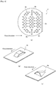
- Fig. 2(a) is a top view illustrating the tray 2 in the apparatus 1 for removing residual monomers shown in Fig. 1 ;
- Fig. 2(b) is a perspective view illustrating the shape of a gas blowout port 2a shown in Fig. 2 (a);
- Fig. 2 (c) is a perspective view illustrating the shape of a gas blowout port 2b.
- the apparatus 1 for removing residual monomers used in the present embodiment has an approximately tube-shaped column main body and multiple valve trays 2 placed therein at a particular gap.
- the column main body also has a polymerization solution inlet port for introduction of the formed polymerization solution in the upper region and a gas inlet port for introduction of an organic solvent gas, i.e., a vaporized organic solvent such as methanol, in the lower region of the column main body.
- the column main body also has a degassing port for discharge of the organic solvent gas together with the monomer in the top region and a outlet port for discharge of the polymer solution after monomer removal in the bottom region.
- each tray 2 installed in the column main body has multiple gas blowout ports 2a each having openings in the direction perpendicular to the flow direction of the polymerization solution, as formed in a matrix shape.
- the gas blowout ports 2a may be configured, for example, to have a through hole formed in the tray bottom face and an arch-shaped cover, as seen from the side, formed over the through hole. As shown in Fig.
- each gas blowout port 2a it is possible to make the openings of each gas blowout port 2a face the direction perpendicular to the flow direction of the polymerization solution, by placing the valve tray 2 in such a manner that the lengthwise direction of the cover of the gas blowout port 2a is in parallel with the flow direction of the polymerization solution.
- the valve tray 2 may have, in addition to the gas blowout ports 2a described above, gas blowout ports 2b having an opening directed downward in the flow direction of the polymerization solution.
- the gas blowout port 2b may be configured, for example, to have a through hole formed in the tray bottom face and a cover formed over the through hole that has an opening only in one direction and is closed in other three directions.
- the gas blowout port 2b can reduce the flow resistance of the polymerization solution, if the cover is formed in the shape ascending in the direction from the edge of the through hole to the opening.
- the positions of the gas blowout ports 2b formed are not particularly limited, but, for example, these ports may be formed in the central region of the tray, as they are aligned in rows in the direction perpendicular to the flow direction of the polymerization solution 4 and separated from each other at a particular gap.
- the flow rate of the polymerization solution is generally smallest in the central region of the tray, but it is possible in such a configuration to make the flow rate of the polymerization solution more uniformized.
- the shape of the through holes for gas blowout ports 2a and 2b is not particularly limited and may be in any shape, e.g., rectangular, trapezoidal, triangular, pentagonal, hexagonal, octagonal, circular or elliptic.
- the heights of the gas blowout ports 2a and 2b are also not particularly limited and can be set properly in accordance with the processing condition of the polymerization solution such as viscosity. However when the height of the gas blowout port 2a or 2b is more than 30 mm, it may result in increase of flow resistance and deterioration in processing efficiency. Thus, the heights of the gas blowout ports 2a and 2b are desirably 30 mm or less.
- the opening areas of the gas blowout ports 2a and 2b can also be set arbitrarily in accordance with the processing condition, but the gas blowout port 2a or 2b having an opening area of less than 300 mm 2 may lead to insufficient amount of the organic solvent gas injected and thus to deterioration in processing efficiency. Therefore, the opening areas of the gas blowout ports 2a and 2b are desirably 300 mm 2 or more.
- the open area ratio of the entire valve tray 2 is desirably 3 to 20%. It is thus possible to improve the efficiency of removing unreacted monomers drastically. An entire-valve-tray open area ratio of less than 3% may result in insufficient contact between the organic solvent gas and the polymerization solution, leading to increased residual of the unreacted monomers. Alternatively, an open area ratio of more than 20% may make it difficult to hold the polymerization solution at a particular depth on the tray 2.
- the valve tray 2 has a liquid-retaining wall 2c formed downstream in the flow direction of the polymerization solution.
- the liquid-retaining wall 2c is formed for preservation of the polymerization fluid at a particular depth, and the height may be, for example, 20 to 100 mm.
- the polymerization solution 4 overflows the liquid-retaining wall 2c into the lower valve tray 2.
- the liquid-retaining wall 2c on the tray 2 is desirably formed, as it is tilted outward at an angle of 5 to 45°. It is possible in this way to suppress residual of the polymerization solution at the bottom of the liquid-retaining wall.
- valve trays 2 described above are placed alternately, for example, such that polymerization-solution flow directions become opposite to each other.
- the number of the stages is not particularly limited, but it is desirably, for example, 10 to 50.
- a method of removing residual monomer from the polymerization solution 4 by using the apparatus 1 for removing residual monomers will be described.
- a polymerization solution 4 is first fed from a polymerization reactor 3 to the top region of the apparatus 1 for removing residual monomers and thus conveyed on the valve trays 2.
- An organic solvent gas such as methanol is introduced from the lower region of the apparatus 1 for removing residual monomers, specifically from the position lower than the lowest stage of the valve tray 2 and injected through the gas blowout holes 2a and 2b in each valve tray 2 into the polymerization solution 4.
- the monomers in the polymerization solution 4 are discharged from the top of the column with the organic solvent gas.
- the monomer-free polymer solution is discharged form the bottom of the column and sent to the saponification step described below.
- the temperature then is preferably 60 to 100°C.
- the concentration of the polymerization solution 4 is desirably 10 to 70 mass % and the viscosity thereof 0.001 to 2.0 Pa • s. It is possible in this way to remove monomers at high efficiency.
- the kind of the organic solvent used in removal of the residual monomers from the polymerization solution 4 is not limited to methanol, as described above, and may be any solvent, if it is volatile. However because the organic solvent used then is the solvent in the saponification step described below, the organic solvent gas used for removal of residual monomers is desirably methanol.
- the monomer-removed polymer (polyvinyl ester) solution is then saponified in a solvent including the organic solvent described above in the presence of a catalyst.
- Alcohols such as methanol, ethanol, propanol, ethylene glycol, propylene glycol, glycerol and diethylene glycol can be used as the solvents for use, but methanol is particularly preferable.
- the saponification catalysts include alkali catalysts such as sodium hydroxide, potassium hydroxide, sodium alcoholate and sodium carbonate and acid catalysts such as sulfuric acid, phosphoric acid and hydrochloric acid.
- alkali catalysts such as sodium hydroxide, potassium hydroxide, sodium alcoholate and sodium carbonate
- acid catalysts such as sulfuric acid, phosphoric acid and hydrochloric acid.
- use of an alkali catalyst is preferable and use of sodium hydroxide is more preferable. It is thus possible to raise saponification rate and improve productivity.
- the saponification step part or all of the vinyl ester groups in the polyvinyl ester are saponificated to vinyl alcohol groups.
- the saponification degree of the PVA resin obtained in the saponification step described above is not particularly limited and may be determined arbitrarily, for example, in accordance with its application.
- a washing step for removal of impurities such as sodium acetate and a drying step may be carried out, as needed, after the polymerization and saponification steps above.
- valve trays having gas blowout ports having openings in the direction perpendicular to the flow direction of the polymerization solution or opening directed downward in the flow direction are used in a shape lower in flow resistance, in the monomer-removing step. It is thus possible to make the depth of the polymerization solution uniformized, to make the flow resistance smaller than that by use of conventional trays, and to elongate the contact time between the organic solvent gas and the polymerization solution. It is thus possible to improve the processing efficiency and reduce the amount of the organic solvent gas used.
- Unreacted vinyl acetate was removed from a polyvinyl acetate solution (polymerization solution) obtained by polymerization of vinyl acetate under the condition shown in the following Table 2.
- the results are summarized in the following Table 2.
- the "distilled amount” shown in the following Table 2 is the total amount of the unreacted monomers and methanol discharged from the top of the column.
- the “discharged amount” and “viscosity” of the polymer solution are respectively the amount and the viscosity of the polyvinyl acetate-methanol solution discharged from the bottom of the column after removal of the monomers.
- the amount of methanol injected could be reduced significantly in the apparatus for removing residual monomers of Example, where valve trays were used, compared to the conventional apparatus, where bubble cap trays were used.
- Figs. 3(a) and 3(b) are charts showing the results of flow analysis of the polymerization solution when the apparatus for removing residual monomers of Example was used.
- Fig. 3(a) shows a difference in liquid depth
- Fig. 3(b) shows the pressure distribution.
- Figs. 4(a) and 4(b) are charts showing the results of flow analysis of the polymerization solution when the apparatus for removing residual monomers of Comparative Example was used.
- Fig. 4(a) shows a difference in liquid depth
- Fig. 4(b) shows the pressure distribution.
- the Comparative Example where the bubble cap trays shown in Figs.
Landscapes
- Chemical & Material Sciences (AREA)
- Chemical Kinetics & Catalysis (AREA)
- Health & Medical Sciences (AREA)
- Medicinal Chemistry (AREA)
- Polymers & Plastics (AREA)
- Organic Chemistry (AREA)
- Dispersion Chemistry (AREA)
- General Chemical & Material Sciences (AREA)
- Addition Polymer Or Copolymer, Post-Treatments, Or Chemical Modifications (AREA)
- Polymerisation Methods In General (AREA)
Claims (6)
- Appareil (1) permettant d'éliminer des monomères résiduels, qui comprend au moins :un corps principal de colonne ; etdes plateaux à clapets (2) dotés de multiples orifices de dégagement gazeux (2a, 2b) ayant des ouvertures uniquement dans une direction perpendiculaire à une direction de l'écoulement d'une solution de polymérisation (4) ou ayant des ouvertures dirigées vers l'aval dans la direction de l'écoulement de la solution de polymérisation (3), oùles plateaux (2) sont agencés en des étages multiples dans le corps principal de colonne, où les plateaux (2) présentent des cloisons de retenue de liquide (2c) formées en aval dans la direction de l'écoulement de la solution de polymérisation (4) et où la cloison de retenue de liquide (2c) est positionnée de manière inclinée vers l'extérieur à un angle de 5 à 45°.
- Appareil (1) permettant d'éliminer des monomères résiduels selon la revendication 1, où chacun des orifices de dégagement gazeux (2a) est configuré de manière à présenter un trou débouchant formé dans la face inférieure d'un plateau et une couverture arquée formée au-dessus du trou débouchant et où le plateau (2) est placé d'une manière telle que la direction longitudinale de la couverture de l'orifice de dégagement gazeux (2a) est la même que la direction de l'écoulement de la solution de polymérisation (4).
- Appareil (1) permettant d'éliminer des monomères résiduels selon les revendications 1 à 2, où chacun des orifices de dégagement gazeux (2a) est configuré de manière à présenter le trou débouchant formé dans la face inférieure du plateau et une couverture formée au-dessus du trou débouchant qui a une ouverture uniquement dans une direction et où le plateau (2) est placé d'une manière telle que l'ouverture de chacun des orifices de dégagement gazeux (2a) est dirigée vers l'aval dans la direction de l'écoulement de la solution de polymérisation (4).
- Utilisation de l'appareil (1) permettant d'éliminer des monomères résiduels selon l'une quelconque des revendications 1 à 3, où l'appareil (1) est utilisé dans un procédé de production d'un alcool polyvinylique.
- Méthode de production d'une résine d'alcool polyvinylique, qui comprend au moins :une étape de polymérisation pour polymériser un ou plusieurs esters de vinyle ou pour copolymériser un ester de vinyle avec d'autres monomères copolymérisables avec celui-ci ;une étape d'élimination de monomères pour éliminer les monomères qui n'ont pas réagi en mettant un solvant organique gazeux en contact avec la solution de polymérisation (4) obtenue à l'étape de polymérisation ; etune étape de saponification pour saponifier la solution exempte de monomères qui n'ont pas réagi dans un solvant contenant le solvant organique en la présence d'un catalyseur alcalin, oùles monomères qui n'ont pas réagi sont éliminés de la solution de polymérisation (4) à l'étape d'élimination de monomères en utilisant un appareil (1) permettant d'éliminer des monomères résiduels selon la revendication 1.
- Méthode de production d'une résine d'alcool polyvinylique selon la revendication 5, où le méthanol est utilisé comme solvant organique.
Applications Claiming Priority (2)
| Application Number | Priority Date | Filing Date | Title |
|---|---|---|---|
| JP2010062309 | 2010-03-18 | ||
| PCT/JP2010/071792 WO2011114585A1 (fr) | 2010-03-18 | 2010-12-06 | Dispositif d'élimination de monomères résiduels et procédé de fabrication de résines d'alcool polyvinylique |
Publications (3)
| Publication Number | Publication Date |
|---|---|
| EP2548896A1 EP2548896A1 (fr) | 2013-01-23 |
| EP2548896A4 EP2548896A4 (fr) | 2014-05-28 |
| EP2548896B1 true EP2548896B1 (fr) | 2017-03-08 |
Family
ID=44648703
Family Applications (1)
| Application Number | Title | Priority Date | Filing Date |
|---|---|---|---|
| EP10847991.6A Active EP2548896B1 (fr) | 2010-03-18 | 2010-12-06 | Dispositif d'élimination de monomères résiduels et procédé de fabrication de résines d'alcool polyvinylique |
Country Status (7)
| Country | Link |
|---|---|
| US (1) | US9022362B2 (fr) |
| EP (1) | EP2548896B1 (fr) |
| JP (1) | JP5759979B2 (fr) |
| CN (1) | CN102803305B (fr) |
| SG (1) | SG184050A1 (fr) |
| TW (1) | TW201132658A (fr) |
| WO (1) | WO2011114585A1 (fr) |
Families Citing this family (4)
| Publication number | Priority date | Publication date | Assignee | Title |
|---|---|---|---|---|
| WO2015033566A1 (fr) * | 2013-09-09 | 2015-03-12 | パナソニックIpマネジメント株式会社 | Dispositif de stockage d'électricité, méthode de fabrication associée, et séparateur |
| CN106117399B (zh) * | 2016-08-17 | 2019-02-26 | 中国石化长城能源化工(宁夏)有限公司 | 一种pva多品种聚合系统生产装置 |
| CN115947444A (zh) * | 2023-03-13 | 2023-04-11 | 湖南博世科环保科技有限公司 | 一种基于臭氧的深度处理装置及废水深度处理系统 |
| KR20260046869A (ko) * | 2024-09-30 | 2026-04-07 | 한화솔루션 주식회사 | 잔류 모노머 제거장치 |
Family Cites Families (15)
| Publication number | Priority date | Publication date | Assignee | Title |
|---|---|---|---|---|
| US3463464A (en) * | 1967-09-26 | 1969-08-26 | Irvin E Nutter | Fluid contact tray |
| GB1449278A (en) | 1973-11-02 | 1976-09-15 | Vyzk Ustav Chem Zarizeni | Gas/liquid contact columns |
| JPS5147076A (en) * | 1974-10-19 | 1976-04-22 | Shinetsu Chemical Co | Jugotaikara mihannotanryotai oyobi kihatsuseijukiseibuno bunrisuru hoho |
| JPS5348850Y2 (fr) * | 1976-04-26 | 1978-11-22 | ||
| JPS52144242A (en) | 1976-05-27 | 1977-12-01 | Mitsubishi Electric Corp | Multi-task control system |
| JPS608687B2 (ja) * | 1980-05-12 | 1985-03-05 | 徳山積水工業株式会社 | 酢酸ビニル重合体の製造方法 |
| US5360583A (en) * | 1993-06-17 | 1994-11-01 | Nutter Dale E | High capacity tray for gas-liquid contact apparatus |
| US5468425A (en) * | 1993-06-17 | 1995-11-21 | Nutter; Dale E. | Gas-liquid contact apparatus including trays with vapor apertures in overlapping panel margins |
| JP3724012B2 (ja) | 1995-08-04 | 2005-12-07 | チッソ株式会社 | 残留モノマー除去装置およびそれを用いる残留モノマー除去方法 |
| JPH0987320A (ja) * | 1995-09-20 | 1997-03-31 | Shin Etsu Chem Co Ltd | ビニルエステル系重合体組成物からの単量体除去方法及び装置 |
| US5788894A (en) * | 1996-04-05 | 1998-08-04 | Koch Engineering Company, Inc. | High capacity vapor-liquid contact tray |
| JP2001233914A (ja) * | 2000-02-21 | 2001-08-28 | Nippon Synthetic Chem Ind Co Ltd:The | 酢酸ビニル系重合体の製造法 |
| JP4620284B2 (ja) | 2001-03-30 | 2011-01-26 | 日本酢ビ・ポバール株式会社 | 環状カーボネート基含有ビニルアルコール系重合体の製造方法 |
| CA2515356C (fr) * | 2003-02-06 | 2011-06-07 | Sulzer Chemtech Ag | Appareil a plateaux, colonne munie de cet appareil et procede d'assemblage et d'utilisation correspondant |
| JP4791216B2 (ja) | 2006-03-14 | 2011-10-12 | 日本酢ビ・ポバール株式会社 | 樹脂の洗浄方法およびその方法により洗浄された樹脂 |
-
2010
- 2010-12-06 EP EP10847991.6A patent/EP2548896B1/fr active Active
- 2010-12-06 CN CN201080065559.2A patent/CN102803305B/zh active Active
- 2010-12-06 WO PCT/JP2010/071792 patent/WO2011114585A1/fr not_active Ceased
- 2010-12-06 SG SG2012067872A patent/SG184050A1/en unknown
- 2010-12-06 JP JP2012505452A patent/JP5759979B2/ja active Active
- 2010-12-06 US US13/634,322 patent/US9022362B2/en active Active
- 2010-12-22 TW TW099145296A patent/TW201132658A/zh unknown
Non-Patent Citations (1)
| Title |
|---|
| None * |
Also Published As
| Publication number | Publication date |
|---|---|
| TW201132658A (en) | 2011-10-01 |
| EP2548896A1 (fr) | 2013-01-23 |
| SG184050A1 (en) | 2012-10-30 |
| US9022362B2 (en) | 2015-05-05 |
| JPWO2011114585A1 (ja) | 2013-06-27 |
| JP5759979B2 (ja) | 2015-08-05 |
| CN102803305A (zh) | 2012-11-28 |
| US20130005906A1 (en) | 2013-01-03 |
| CN102803305B (zh) | 2015-11-25 |
| EP2548896A4 (fr) | 2014-05-28 |
| WO2011114585A1 (fr) | 2011-09-22 |
Similar Documents
| Publication | Publication Date | Title |
|---|---|---|
| CN1143330A (zh) | 供脱降聚合物中挥发分的改进型平板热交换器设计的设备 | |
| US9022362B2 (en) | Residual monomer elimination device and polyvinyl alcohol resin production method | |
| KR100998468B1 (ko) | 대량 처리가능한 중합체로부터 휘발성 재료들을 제거하는장치 및 방법 | |
| CN111699202B (zh) | 一种回收溶液聚合过程中的烯烃的方法 | |
| EP3805280A1 (fr) | Procédé de production d'un copolymère d'éthylène-acétate de vinyle | |
| KR101974295B1 (ko) | 중합체로부터 탄화수소를 분리하는 방법 | |
| CN108025220A (zh) | 用于热处理流体混合物、特别是含有(甲基)丙烯酸单体的流体混合物的塔 | |
| US11149096B2 (en) | Method of recovering olefins in a solution polymerization process | |
| JP5758879B2 (ja) | ポリビニルアルコールの製造方法及び製造装置 | |
| CN109715675B (zh) | 用于从聚合物中分离碳氢化合物的方法 | |
| CN1974522A (zh) | 处理可聚合材料的设备 | |
| CN113164828A (zh) | 用于将挥发性化合物从聚合物溶液中分离的分离器和方法 | |
| CN100427451C (zh) | (甲基)丙烯酸或(甲基)丙烯酸酯的制备方法 | |
| CN105567301B (zh) | 一种抽提塔和溶剂脱沥青的方法 | |
| CN108686590A (zh) | 使用串联的n个塔的模拟移动床分离方法的收集和分布通道的新颖构思 | |
| US11813552B2 (en) | Dispersing apparatus and defoaming apparatus comprising same | |
| EP4691590A1 (fr) | Appareil de séparation de monomères réactifs | |
| CN217248852U (zh) | 一种乙烯-乙烯醇的生产系统 | |
| KR102734942B1 (ko) | 트레이형 증류장치 | |
| KR20250149750A (ko) | 에틸렌계 중합체 및 에틸렌계 중합체의 제조 방법 | |
| KR20220048851A (ko) | 탈휘발/증발 장치 | |
| CN120021414A (zh) | 反应性单体分离装置 | |
| KR101832304B1 (ko) | 기상 중합 반응기 및 이를 이용한 알파-올레핀의 중합 방법 | |
| CN102350294B (zh) | 基于喷射器的逆流式传质、传热、反应装置 |
Legal Events
| Date | Code | Title | Description |
|---|---|---|---|
| PUAI | Public reference made under article 153(3) epc to a published international application that has entered the european phase |
Free format text: ORIGINAL CODE: 0009012 |
|
| 17P | Request for examination filed |
Effective date: 20120913 |
|
| AK | Designated contracting states |
Kind code of ref document: A1 Designated state(s): AL AT BE BG CH CY CZ DE DK EE ES FI FR GB GR HR HU IE IS IT LI LT LU LV MC MK MT NL NO PL PT RO RS SE SI SK SM TR |
|
| DAX | Request for extension of the european patent (deleted) | ||
| A4 | Supplementary search report drawn up and despatched |
Effective date: 20140430 |
|
| RIC1 | Information provided on ipc code assigned before grant |
Ipc: C08F 6/10 20060101AFI20140424BHEP Ipc: C08F 16/06 20060101ALI20140424BHEP Ipc: B01D 3/22 20060101ALI20140424BHEP |
|
| 17Q | First examination report despatched |
Effective date: 20150731 |
|
| RAP1 | Party data changed (applicant data changed or rights of an application transferred) |
Owner name: DENKA COMPANY LIMITED |
|
| GRAP | Despatch of communication of intention to grant a patent |
Free format text: ORIGINAL CODE: EPIDOSNIGR1 |
|
| INTG | Intention to grant announced |
Effective date: 20160921 |
|
| GRAS | Grant fee paid |
Free format text: ORIGINAL CODE: EPIDOSNIGR3 |
|
| GRAA | (expected) grant |
Free format text: ORIGINAL CODE: 0009210 |
|
| AK | Designated contracting states |
Kind code of ref document: B1 Designated state(s): AL AT BE BG CH CY CZ DE DK EE ES FI FR GB GR HR HU IE IS IT LI LT LU LV MC MK MT NL NO PL PT RO RS SE SI SK SM TR |
|
| REG | Reference to a national code |
Ref country code: GB Ref legal event code: FG4D |
|
| REG | Reference to a national code |
Ref country code: CH Ref legal event code: EP Ref country code: AT Ref legal event code: REF Ref document number: 873441 Country of ref document: AT Kind code of ref document: T Effective date: 20170315 |
|
| REG | Reference to a national code |
Ref country code: IE Ref legal event code: FG4D |
|
| REG | Reference to a national code |
Ref country code: DE Ref legal event code: R096 Ref document number: 602010040677 Country of ref document: DE |
|
| REG | Reference to a national code |
Ref country code: LT Ref legal event code: MG4D |
|
| REG | Reference to a national code |
Ref country code: NL Ref legal event code: MP Effective date: 20170308 |
|
| PG25 | Lapsed in a contracting state [announced via postgrant information from national office to epo] |
Ref country code: FI Free format text: LAPSE BECAUSE OF FAILURE TO SUBMIT A TRANSLATION OF THE DESCRIPTION OR TO PAY THE FEE WITHIN THE PRESCRIBED TIME-LIMIT Effective date: 20170308 Ref country code: NO Free format text: LAPSE BECAUSE OF FAILURE TO SUBMIT A TRANSLATION OF THE DESCRIPTION OR TO PAY THE FEE WITHIN THE PRESCRIBED TIME-LIMIT Effective date: 20170608 Ref country code: LT Free format text: LAPSE BECAUSE OF FAILURE TO SUBMIT A TRANSLATION OF THE DESCRIPTION OR TO PAY THE FEE WITHIN THE PRESCRIBED TIME-LIMIT Effective date: 20170308 Ref country code: HR Free format text: LAPSE BECAUSE OF FAILURE TO SUBMIT A TRANSLATION OF THE DESCRIPTION OR TO PAY THE FEE WITHIN THE PRESCRIBED TIME-LIMIT Effective date: 20170308 Ref country code: GR Free format text: LAPSE BECAUSE OF FAILURE TO SUBMIT A TRANSLATION OF THE DESCRIPTION OR TO PAY THE FEE WITHIN THE PRESCRIBED TIME-LIMIT Effective date: 20170609 |
|
| REG | Reference to a national code |
Ref country code: AT Ref legal event code: MK05 Ref document number: 873441 Country of ref document: AT Kind code of ref document: T Effective date: 20170308 |
|
| PG25 | Lapsed in a contracting state [announced via postgrant information from national office to epo] |
Ref country code: ES Free format text: LAPSE BECAUSE OF FAILURE TO SUBMIT A TRANSLATION OF THE DESCRIPTION OR TO PAY THE FEE WITHIN THE PRESCRIBED TIME-LIMIT Effective date: 20170308 Ref country code: LV Free format text: LAPSE BECAUSE OF FAILURE TO SUBMIT A TRANSLATION OF THE DESCRIPTION OR TO PAY THE FEE WITHIN THE PRESCRIBED TIME-LIMIT Effective date: 20170308 Ref country code: BG Free format text: LAPSE BECAUSE OF FAILURE TO SUBMIT A TRANSLATION OF THE DESCRIPTION OR TO PAY THE FEE WITHIN THE PRESCRIBED TIME-LIMIT Effective date: 20170608 Ref country code: RS Free format text: LAPSE BECAUSE OF FAILURE TO SUBMIT A TRANSLATION OF THE DESCRIPTION OR TO PAY THE FEE WITHIN THE PRESCRIBED TIME-LIMIT Effective date: 20170308 Ref country code: SE Free format text: LAPSE BECAUSE OF FAILURE TO SUBMIT A TRANSLATION OF THE DESCRIPTION OR TO PAY THE FEE WITHIN THE PRESCRIBED TIME-LIMIT Effective date: 20170308 |
|
| PG25 | Lapsed in a contracting state [announced via postgrant information from national office to epo] |
Ref country code: NL Free format text: LAPSE BECAUSE OF FAILURE TO SUBMIT A TRANSLATION OF THE DESCRIPTION OR TO PAY THE FEE WITHIN THE PRESCRIBED TIME-LIMIT Effective date: 20170308 |
|
| PG25 | Lapsed in a contracting state [announced via postgrant information from national office to epo] |
Ref country code: EE Free format text: LAPSE BECAUSE OF FAILURE TO SUBMIT A TRANSLATION OF THE DESCRIPTION OR TO PAY THE FEE WITHIN THE PRESCRIBED TIME-LIMIT Effective date: 20170308 Ref country code: RO Free format text: LAPSE BECAUSE OF FAILURE TO SUBMIT A TRANSLATION OF THE DESCRIPTION OR TO PAY THE FEE WITHIN THE PRESCRIBED TIME-LIMIT Effective date: 20170308 Ref country code: CZ Free format text: LAPSE BECAUSE OF FAILURE TO SUBMIT A TRANSLATION OF THE DESCRIPTION OR TO PAY THE FEE WITHIN THE PRESCRIBED TIME-LIMIT Effective date: 20170308 Ref country code: SK Free format text: LAPSE BECAUSE OF FAILURE TO SUBMIT A TRANSLATION OF THE DESCRIPTION OR TO PAY THE FEE WITHIN THE PRESCRIBED TIME-LIMIT Effective date: 20170308 Ref country code: AT Free format text: LAPSE BECAUSE OF FAILURE TO SUBMIT A TRANSLATION OF THE DESCRIPTION OR TO PAY THE FEE WITHIN THE PRESCRIBED TIME-LIMIT Effective date: 20170308 Ref country code: IT Free format text: LAPSE BECAUSE OF FAILURE TO SUBMIT A TRANSLATION OF THE DESCRIPTION OR TO PAY THE FEE WITHIN THE PRESCRIBED TIME-LIMIT Effective date: 20170308 |
|
| PG25 | Lapsed in a contracting state [announced via postgrant information from national office to epo] |
Ref country code: PL Free format text: LAPSE BECAUSE OF FAILURE TO SUBMIT A TRANSLATION OF THE DESCRIPTION OR TO PAY THE FEE WITHIN THE PRESCRIBED TIME-LIMIT Effective date: 20170308 Ref country code: SM Free format text: LAPSE BECAUSE OF FAILURE TO SUBMIT A TRANSLATION OF THE DESCRIPTION OR TO PAY THE FEE WITHIN THE PRESCRIBED TIME-LIMIT Effective date: 20170308 Ref country code: IS Free format text: LAPSE BECAUSE OF FAILURE TO SUBMIT A TRANSLATION OF THE DESCRIPTION OR TO PAY THE FEE WITHIN THE PRESCRIBED TIME-LIMIT Effective date: 20170708 Ref country code: PT Free format text: LAPSE BECAUSE OF FAILURE TO SUBMIT A TRANSLATION OF THE DESCRIPTION OR TO PAY THE FEE WITHIN THE PRESCRIBED TIME-LIMIT Effective date: 20170710 |
|
| REG | Reference to a national code |
Ref country code: DE Ref legal event code: R097 Ref document number: 602010040677 Country of ref document: DE |
|
| PLBE | No opposition filed within time limit |
Free format text: ORIGINAL CODE: 0009261 |
|
| STAA | Information on the status of an ep patent application or granted ep patent |
Free format text: STATUS: NO OPPOSITION FILED WITHIN TIME LIMIT |
|
| PG25 | Lapsed in a contracting state [announced via postgrant information from national office to epo] |
Ref country code: DK Free format text: LAPSE BECAUSE OF FAILURE TO SUBMIT A TRANSLATION OF THE DESCRIPTION OR TO PAY THE FEE WITHIN THE PRESCRIBED TIME-LIMIT Effective date: 20170308 |
|
| 26N | No opposition filed |
Effective date: 20171211 |
|
| PG25 | Lapsed in a contracting state [announced via postgrant information from national office to epo] |
Ref country code: SI Free format text: LAPSE BECAUSE OF FAILURE TO SUBMIT A TRANSLATION OF THE DESCRIPTION OR TO PAY THE FEE WITHIN THE PRESCRIBED TIME-LIMIT Effective date: 20170308 |
|
| REG | Reference to a national code |
Ref country code: CH Ref legal event code: PL |
|
| GBPC | Gb: european patent ceased through non-payment of renewal fee |
Effective date: 20171206 |
|
| REG | Reference to a national code |
Ref country code: IE Ref legal event code: MM4A |
|
| PG25 | Lapsed in a contracting state [announced via postgrant information from national office to epo] |
Ref country code: LU Free format text: LAPSE BECAUSE OF NON-PAYMENT OF DUE FEES Effective date: 20171206 Ref country code: MT Free format text: LAPSE BECAUSE OF NON-PAYMENT OF DUE FEES Effective date: 20171206 |
|
| REG | Reference to a national code |
Ref country code: FR Ref legal event code: ST Effective date: 20180831 |
|
| REG | Reference to a national code |
Ref country code: BE Ref legal event code: MM Effective date: 20171231 |
|
| PG25 | Lapsed in a contracting state [announced via postgrant information from national office to epo] |
Ref country code: FR Free format text: LAPSE BECAUSE OF NON-PAYMENT OF DUE FEES Effective date: 20180102 Ref country code: IE Free format text: LAPSE BECAUSE OF NON-PAYMENT OF DUE FEES Effective date: 20171206 |
|
| PG25 | Lapsed in a contracting state [announced via postgrant information from national office to epo] |
Ref country code: LI Free format text: LAPSE BECAUSE OF NON-PAYMENT OF DUE FEES Effective date: 20171231 Ref country code: CH Free format text: LAPSE BECAUSE OF NON-PAYMENT OF DUE FEES Effective date: 20171231 Ref country code: GB Free format text: LAPSE BECAUSE OF NON-PAYMENT OF DUE FEES Effective date: 20171206 Ref country code: BE Free format text: LAPSE BECAUSE OF NON-PAYMENT OF DUE FEES Effective date: 20171231 |
|
| PG25 | Lapsed in a contracting state [announced via postgrant information from national office to epo] |
Ref country code: HU Free format text: LAPSE BECAUSE OF FAILURE TO SUBMIT A TRANSLATION OF THE DESCRIPTION OR TO PAY THE FEE WITHIN THE PRESCRIBED TIME-LIMIT; INVALID AB INITIO Effective date: 20101206 Ref country code: MC Free format text: LAPSE BECAUSE OF FAILURE TO SUBMIT A TRANSLATION OF THE DESCRIPTION OR TO PAY THE FEE WITHIN THE PRESCRIBED TIME-LIMIT Effective date: 20170308 |
|
| PG25 | Lapsed in a contracting state [announced via postgrant information from national office to epo] |
Ref country code: CY Free format text: LAPSE BECAUSE OF NON-PAYMENT OF DUE FEES Effective date: 20170308 |
|
| PG25 | Lapsed in a contracting state [announced via postgrant information from national office to epo] |
Ref country code: MK Free format text: LAPSE BECAUSE OF FAILURE TO SUBMIT A TRANSLATION OF THE DESCRIPTION OR TO PAY THE FEE WITHIN THE PRESCRIBED TIME-LIMIT Effective date: 20170308 |
|
| REG | Reference to a national code |
Ref country code: DE Ref legal event code: R082 Ref document number: 602010040677 Country of ref document: DE Representative=s name: WITTHOFF JAEKEL STEINECKE PATENTANWAELTE PARTG, DE |
|
| PG25 | Lapsed in a contracting state [announced via postgrant information from national office to epo] |
Ref country code: TR Free format text: LAPSE BECAUSE OF FAILURE TO SUBMIT A TRANSLATION OF THE DESCRIPTION OR TO PAY THE FEE WITHIN THE PRESCRIBED TIME-LIMIT Effective date: 20170308 |
|
| PG25 | Lapsed in a contracting state [announced via postgrant information from national office to epo] |
Ref country code: AL Free format text: LAPSE BECAUSE OF FAILURE TO SUBMIT A TRANSLATION OF THE DESCRIPTION OR TO PAY THE FEE WITHIN THE PRESCRIBED TIME-LIMIT Effective date: 20170308 |
|
| P01 | Opt-out of the competence of the unified patent court (upc) registered |
Effective date: 20230512 |
|
| PGFP | Annual fee paid to national office [announced via postgrant information from national office to epo] |
Ref country code: DE Payment date: 20241029 Year of fee payment: 15 |