EP2549042A1 - Dispositif de facilitation de coulissement - Google Patents
Dispositif de facilitation de coulissement Download PDFInfo
- Publication number
- EP2549042A1 EP2549042A1 EP11756382A EP11756382A EP2549042A1 EP 2549042 A1 EP2549042 A1 EP 2549042A1 EP 11756382 A EP11756382 A EP 11756382A EP 11756382 A EP11756382 A EP 11756382A EP 2549042 A1 EP2549042 A1 EP 2549042A1
- Authority
- EP
- European Patent Office
- Prior art keywords
- latch
- draw
- slider
- case
- standby position
- Prior art date
- Legal status (The legal status is an assumption and is not a legal conclusion. Google has not performed a legal analysis and makes no representation as to the accuracy of the status listed.)
- Withdrawn
Links
- 238000013016 damping Methods 0.000 claims description 2
- 238000000034 method Methods 0.000 description 4
- 210000000078 claw Anatomy 0.000 description 3
- 230000003139 buffering effect Effects 0.000 description 2
- 238000010586 diagram Methods 0.000 description 2
- 239000011347 resin Substances 0.000 description 2
- 229920005989 resin Polymers 0.000 description 2
- 230000002159 abnormal effect Effects 0.000 description 1
- 230000006835 compression Effects 0.000 description 1
- 238000007906 compression Methods 0.000 description 1
- 230000000994 depressogenic effect Effects 0.000 description 1
- 230000000694 effects Effects 0.000 description 1
- 238000005516 engineering process Methods 0.000 description 1
- 230000001965 increasing effect Effects 0.000 description 1
Images





Classifications
-
- E—FIXED CONSTRUCTIONS
- E05—LOCKS; KEYS; WINDOW OR DOOR FITTINGS; SAFES
- E05C—BOLTS OR FASTENING DEVICES FOR WINGS, SPECIALLY FOR DOORS OR WINDOWS
- E05C21/00—Arrangements or combinations of wing fastening, securing, or holding devices, not covered by a single preceding main group; Locking kits
-
- E—FIXED CONSTRUCTIONS
- E05—LOCKS; KEYS; WINDOW OR DOOR FITTINGS; SAFES
- E05F—DEVICES FOR MOVING WINGS INTO OPEN OR CLOSED POSITION; CHECKS FOR WINGS; WING FITTINGS NOT OTHERWISE PROVIDED FOR, CONCERNED WITH THE FUNCTIONING OF THE WING
- E05F1/00—Closers or openers for wings, not otherwise provided for in this subclass
- E05F1/08—Closers or openers for wings, not otherwise provided for in this subclass spring-actuated, e.g. for horizontally sliding wings
- E05F1/16—Closers or openers for wings, not otherwise provided for in this subclass spring-actuated, e.g. for horizontally sliding wings for sliding wings
-
- E—FIXED CONSTRUCTIONS
- E05—LOCKS; KEYS; WINDOW OR DOOR FITTINGS; SAFES
- E05F—DEVICES FOR MOVING WINGS INTO OPEN OR CLOSED POSITION; CHECKS FOR WINGS; WING FITTINGS NOT OTHERWISE PROVIDED FOR, CONCERNED WITH THE FUNCTIONING OF THE WING
- E05F3/00—Closers or openers with braking devices, e.g. checks; Construction of pneumatic or liquid braking devices
- E05F3/02—Closers or openers with braking devices, e.g. checks; Construction of pneumatic or liquid braking devices with pneumatic piston brakes
-
- E—FIXED CONSTRUCTIONS
- E05—LOCKS; KEYS; WINDOW OR DOOR FITTINGS; SAFES
- E05F—DEVICES FOR MOVING WINGS INTO OPEN OR CLOSED POSITION; CHECKS FOR WINGS; WING FITTINGS NOT OTHERWISE PROVIDED FOR, CONCERNED WITH THE FUNCTIONING OF THE WING
- E05F3/00—Closers or openers with braking devices, e.g. checks; Construction of pneumatic or liquid braking devices
- E05F3/04—Closers or openers with braking devices, e.g. checks; Construction of pneumatic or liquid braking devices with liquid piston brakes
-
- E—FIXED CONSTRUCTIONS
- E05—LOCKS; KEYS; WINDOW OR DOOR FITTINGS; SAFES
- E05F—DEVICES FOR MOVING WINGS INTO OPEN OR CLOSED POSITION; CHECKS FOR WINGS; WING FITTINGS NOT OTHERWISE PROVIDED FOR, CONCERNED WITH THE FUNCTIONING OF THE WING
- E05F5/00—Braking devices, e.g. checks; Stops; Buffers
- E05F5/003—Braking devices, e.g. checks; Stops; Buffers for sliding wings
-
- E—FIXED CONSTRUCTIONS
- E05—LOCKS; KEYS; WINDOW OR DOOR FITTINGS; SAFES
- E05Y—INDEXING SCHEME ASSOCIATED WITH SUBCLASSES E05D AND E05F, RELATING TO CONSTRUCTION ELEMENTS, ELECTRIC CONTROL, POWER SUPPLY, POWER SIGNAL OR TRANSMISSION, USER INTERFACES, MOUNTING OR COUPLING, DETAILS, ACCESSORIES, AUXILIARY OPERATIONS NOT OTHERWISE PROVIDED FOR, APPLICATION THEREOF
- E05Y2201/00—Constructional elements; Accessories therefor
- E05Y2201/40—Motors; Magnets; Springs; Weights; Accessories therefor
- E05Y2201/404—Function thereof
- E05Y2201/41—Function thereof for closing
- E05Y2201/412—Function thereof for closing for the final closing movement
-
- E—FIXED CONSTRUCTIONS
- E05—LOCKS; KEYS; WINDOW OR DOOR FITTINGS; SAFES
- E05Y—INDEXING SCHEME ASSOCIATED WITH SUBCLASSES E05D AND E05F, RELATING TO CONSTRUCTION ELEMENTS, ELECTRIC CONTROL, POWER SUPPLY, POWER SIGNAL OR TRANSMISSION, USER INTERFACES, MOUNTING OR COUPLING, DETAILS, ACCESSORIES, AUXILIARY OPERATIONS NOT OTHERWISE PROVIDED FOR, APPLICATION THEREOF
- E05Y2201/00—Constructional elements; Accessories therefor
- E05Y2201/40—Motors; Magnets; Springs; Weights; Accessories therefor
- E05Y2201/404—Function thereof
- E05Y2201/422—Function thereof for opening
- E05Y2201/424—Function thereof for opening for the final opening movement
-
- E—FIXED CONSTRUCTIONS
- E05—LOCKS; KEYS; WINDOW OR DOOR FITTINGS; SAFES
- E05Y—INDEXING SCHEME ASSOCIATED WITH SUBCLASSES E05D AND E05F, RELATING TO CONSTRUCTION ELEMENTS, ELECTRIC CONTROL, POWER SUPPLY, POWER SIGNAL OR TRANSMISSION, USER INTERFACES, MOUNTING OR COUPLING, DETAILS, ACCESSORIES, AUXILIARY OPERATIONS NOT OTHERWISE PROVIDED FOR, APPLICATION THEREOF
- E05Y2201/00—Constructional elements; Accessories therefor
- E05Y2201/40—Motors; Magnets; Springs; Weights; Accessories therefor
- E05Y2201/47—Springs
- E05Y2201/496—Double acting springs
-
- E—FIXED CONSTRUCTIONS
- E05—LOCKS; KEYS; WINDOW OR DOOR FITTINGS; SAFES
- E05Y—INDEXING SCHEME ASSOCIATED WITH SUBCLASSES E05D AND E05F, RELATING TO CONSTRUCTION ELEMENTS, ELECTRIC CONTROL, POWER SUPPLY, POWER SIGNAL OR TRANSMISSION, USER INTERFACES, MOUNTING OR COUPLING, DETAILS, ACCESSORIES, AUXILIARY OPERATIONS NOT OTHERWISE PROVIDED FOR, APPLICATION THEREOF
- E05Y2600/00—Mounting or coupling arrangements for elements provided for in this subclass
- E05Y2600/40—Mounting location; Visibility of the elements
- E05Y2600/41—Concealed
-
- E—FIXED CONSTRUCTIONS
- E05—LOCKS; KEYS; WINDOW OR DOOR FITTINGS; SAFES
- E05Y—INDEXING SCHEME ASSOCIATED WITH SUBCLASSES E05D AND E05F, RELATING TO CONSTRUCTION ELEMENTS, ELECTRIC CONTROL, POWER SUPPLY, POWER SIGNAL OR TRANSMISSION, USER INTERFACES, MOUNTING OR COUPLING, DETAILS, ACCESSORIES, AUXILIARY OPERATIONS NOT OTHERWISE PROVIDED FOR, APPLICATION THEREOF
- E05Y2600/00—Mounting or coupling arrangements for elements provided for in this subclass
- E05Y2600/40—Mounting location; Visibility of the elements
- E05Y2600/46—Mounting location; Visibility of the elements in or on the wing
-
- E—FIXED CONSTRUCTIONS
- E05—LOCKS; KEYS; WINDOW OR DOOR FITTINGS; SAFES
- E05Y—INDEXING SCHEME ASSOCIATED WITH SUBCLASSES E05D AND E05F, RELATING TO CONSTRUCTION ELEMENTS, ELECTRIC CONTROL, POWER SUPPLY, POWER SIGNAL OR TRANSMISSION, USER INTERFACES, MOUNTING OR COUPLING, DETAILS, ACCESSORIES, AUXILIARY OPERATIONS NOT OTHERWISE PROVIDED FOR, APPLICATION THEREOF
- E05Y2800/00—Details, accessories and auxiliary operations not otherwise provided for
- E05Y2800/73—Multiple functions
-
- E—FIXED CONSTRUCTIONS
- E05—LOCKS; KEYS; WINDOW OR DOOR FITTINGS; SAFES
- E05Y—INDEXING SCHEME ASSOCIATED WITH SUBCLASSES E05D AND E05F, RELATING TO CONSTRUCTION ELEMENTS, ELECTRIC CONTROL, POWER SUPPLY, POWER SIGNAL OR TRANSMISSION, USER INTERFACES, MOUNTING OR COUPLING, DETAILS, ACCESSORIES, AUXILIARY OPERATIONS NOT OTHERWISE PROVIDED FOR, APPLICATION THEREOF
- E05Y2900/00—Application of doors, windows, wings or fittings thereof
- E05Y2900/10—Application of doors, windows, wings or fittings thereof for buildings or parts thereof
- E05Y2900/13—Type of wing
- E05Y2900/132—Doors
Definitions
- the present invention relates to a slide assist device which assists an operation switching a mobile body such as a sliding door, a door, and the like from a first position on a main body side to a second position, or an operation switching the mobile body from the second position to the first position, by an urging force.
- a slide assist device which assists an operation switching a mobile body such as a sliding door, a door, and the like from a first position on a main body side to a second position, or an operation switching the mobile body from the second position to the first position, by an urging force.
- Figs. 12(a) and 12(b) show a slide assist device of the following Patent Document 1. Characteristics of the device are that a main body frame slidably disposes the sliding door or the door; a projecting body 9 which is an actuating member is provided in the sliding door or the door; and the sliding door or the door is drawn in through the projecting body 9 by a draw-in unit which is a main portion of the slide assist device provided in the main body frame.
- the draw-in unit comprises a case 1 attached to the main body frame; sliders 2A and 2B slidably placed on the case 1; latches 5 and 5 pivotally supported relative to each slider through a shaft 8; and an urging device 3.
- the projecting body 9 is provided to protrude on an upper end surface side of the sliding door or the door.
- each slider 2A and 2B includes a convex portion 22 provided on upper and lower surfaces.
- Each convex portion 22 fits into guide grooves 12b and 16b provided on the upper and lower surfaces of the case 1, and each convex portion 22 is slid while being guided by the upper and lower guide devices.
- each latch 5 includes a protrusion 52 provided on the upper and lower surfaces.
- the respective protrusions 52 fit into guide grooves 14 and 19 provided on the upper and lower surfaces of the case 1, and the respective protrusions 52 slide while being guided by the upper and lower guide devices.
- the respective guide grooves 14 and 19 include straight grooves 14a and 19a parallel to the guide grooves 12b and 16b, and locking grooves 14b and 19b with an approximately L shape provided on both sides of the straight grooves 14a and 19a.
- the latches 5 on both sides in Fig. 12(a) and the latch 5 on the right side in Fig. 12 (b) are in a standby position.
- the latches 5 in the standby position the upper and lower protrusions 52 are locked in the corresponding locking grooves 14b and 19b, and positions of the latches 5 are controlled against an urging force accumulated in the urging device 3 together with the slider 2A. Then, from a state shown in Fig.
- the latch 5 and the slider 2A are slid by the urging force accumulated in the urging device 3, and automatically switch the sliding door or the door to a closed position through the projecting body 9. Also, from the closed position, by an opening operation of the sliding door or the door, when the projecting body 9 is slid to the left side of the figure together with the latch 5, accompanied by that, the urging force is accumulated in the urging device 3. Moreover, when the sliding door or the door is moved in an open direction, the latch 5 is switched to the standby position again.
- Patent Document 1 Japanese Unexamined Patent Publication No. 2008-144567
- the sliding door or the door when the sliding door or the door is operated to be closed, the sliding door or the door is automatically switched up to the closed position by the urging force during the middle of the closing operation so as to improve usability of the sliding door or the door, and to be capable of solving an occurrence of an incomplete closed state of the sliding door or the door.
- the slide assist device for example, as with a slide assist mechanism (described in Japanese Unexamined Patent Publication No. 2011-006872 and the like) in which the present applicants have developed previously, on the assumption that the slider is slid in a longitudinal direction inside the case as much as possible, especially, a stable switching actuation from the draw-in position to the standby position of the latch is important, i.e., it is important that the protrusion on a latch side enters into the locking groove from the straight groove on a guide groove side so as to lock the latch, and that the locking cannot be unlocked abruptly by a vibration, an impact, and the like.
- the urging device it is preferable that a coil spring whose entire size is long is used, and also that a sliding speed of the slider is controlled by a braking device.
- a braking device in a case where a piston-type braking device with an excellent braking property is used, structural members (a cylinder and a piston rod) of the braking device thereof have to be fixed to the slider or the case.
- a fixation structure of, especially, the piston rod, which becomes a small diameter becomes a problem.
- the present invention provides a slide assist device having characteristics of either of the following (1) to (4).
- the slide assist device comprises a draw-in unit including a case attached to one of the main body or the mobile body, a slider slidably placed on the case, a latch pivotally supported in the slider, and capable of switching between the standby position locking in the corresponding portion of the case and the draw-in position releasing the aforementioned locking, and an urging device; and an actuating member attached to the other of the main body or the mobile body, and switching the latch from the standby position to the draw-in position, or switching the latch from the draw-in position to the standby position.
- the slide assist device comprises a resistance-imparting portion provided on a sliding-and-contacting surface between the latch and the slider, and acting as a resistance or a friction force when the latch is turned as a supporting point of a pivotal support portion relative to the slider.
- the resistance-imparting portion has a structure including a convex portion or a concave-convex portion provided on at least one sliding-and-contacting surface of the latch or the slider.
- the slide assist device includes a piston-type braking device 5 damping a moving speed from the urging force of the mobile body, a temporary fixing member provided in the slider or the case to temporarily fix structural members of the braking device; and an attachment member firmly fixing the structural members of the braking device by being engaged with the slider or the case.
- the slide assist device is preferred for a fixation structure of especially, a piston rod, which becomes a small diameter, among the structural members of the piston-type braking device. From a state wherein the piston rod is temporarily fixed once, the slide assist device firmly fixes the piston rod by an engaging operation of the attachment member relative to the slider or the case.
- the mobile body there also include, for example, a drawer and the like other than a sliding door or a door.
- the main body there also include a frame for the sliding door or the door, a storage portion for the drawer, and the like.
- the first position shows a completely closed position or a completely open position of the mobile body, and also includes a closed position wherein the mobile body has been completely pushed into the storage portion, or an open position wherein the mobile body has been completely pulled out.
- the second position shows a completely open position or a completely closed position of the mobile body, and also includes an open position wherein the mobile body has been completely pulled out of the storage portion, or a closed position wherein the mobile body has been completely pushed in.
- an outer shape of a cross-section of the axis portion and the axis hole is not a complete circular form, and has a shape including a straight portion in which one portion of a circular arc has been cut out (i.e., a shape close to an alphabet "D"), so that the axis portion has the flat surface in one portion of a side surface thereof, and the axis hole also has the flat surface in one portion of an inner surface thereof. Then, when the latch is in the standby position, a fitted state between the axis portion and the axis hole becomes the most stable fitted state wherein the aforementioned flat surface of the axis portion and the flat surface of the axis hole face approximately in parallel.
- the slide assist device of the aforementioned (1) since the latch is structured so as to increase the resistance when the latch turns from the standby position, the slide assist device can prevent the latch from turning by a vibration, an impact, and the like from an outside. Also, in the slide assist device of the aforementioned (1), the shape of the cross-section of the axis portion and the axis hole has the above-mentioned shape, so that when the latch is switched from the standby position to the draw-in position by the actuating member, the latch is turned at a slow speed so as to be capable of reducing an emanating switchover sound.
- the latch when the latch is turned as the supporting point of the pivotal support portion, the latch receives a resisting force by the resistance-imparting portion, so that the latch cannot be easily turned due to the vibration, the impact, and the like from the outside so as to be capable of preventing a mis-actuation.
- the resistance-imparting portion can be easily added so as to be capable of improving an actuation property.
- the slide assist device having the characteristic of the aforementioned (4), in a case where the actuation property is attempted to be improved by the piston-type braking device, the structural members of the braking device thereof have to be fixed to the slider or the case.
- the slide assist device can easily come out since the slide assist device becomes smaller due to a usage constraint. Accordingly, the slide assist device has been devised.
- the slide assist device is preferred when, especially, the piston rod with the small diameter is fixed. From the state wherein the piston rod is temporarily fixed once, the piston rod is firmly fixed by the engaging operation of the attachment member relative to the slider or the case so as to have an excellent operability.
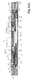
- Fig. 1(a) is a plan view showing a state wherein a cover 15 is removed from a case 1 structuring a draw-in unit 6 of a slide assist device according to an embodiment of the present invention.
- Fig. 1(b) is a right end face view of the draw-in unit 6 in the state wherein the cover 15 is removed from the case 1.
- Fig. 1(c) is a drawing showing an inner surface of the cover 15.
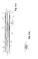
- Fig. 2(a) is a cross-sectional view in a cross-section taken along a line A to A in Fig. 1(a) .
- Fig. 2(b) is a cross-sectional view in a cross-section taken along a line B to B in Fig.
- Fig. 2(c) is a cross-sectional view in a cross-section taken along a line C to C in Fig. 1(a) .
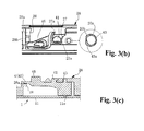
- Fig. 3(a) is a schematic view wherein an inside of a frame shown by assigning the reference alphabet "D" in Fig. 1(a) is enlarged, and shows a standby position of a latch 4.
- Fig. 3(b) is a schematic view wherein the inside of the frame shown by assigning the reference alphabet "D" in Fig. 1(a) is enlarged, and shows a draw-in position of the latch 4.
- Fig. 3(c) is a cross-sectional view in a cross-section taken along a line E to E in Fig. 3(a) .
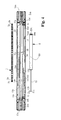
- Fig. 4 is a plan view showing the case 1 without the cover 15 together with an urging device and a braking device.
- Fig. 5(a) is a plan view of a slider 2A on the left side of Fig. 1(a) .
- Fig. 5(b) is a bottom view of the slider 2A on the left side of Fig. 1(a) .
- Fig. 6(a) is a plan view of a slider 2B on the right side of Fig. 1(a) .
- Fig. 6(b) is a bottom view of the slider 2B on the right side of Fig. 1(a) .
- Fig. 5(a) is a plan view of a slider 2A on the left side of Fig. 1(a) .
- Fig. 6(b) is a bottom view of the slider 2B on the right side of Fig. 1(a) .
- Fig. 5(a) is a plan view of a slider 2A on the left
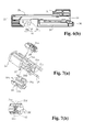
- FIG. 7 (a) is a drawing showing a structure inside a frame shown by assigning the reference alphabet "F” in Fig. 5(a) .
- Fig. 7(b) is a plan view of a connecting portion 21 in a state wherein an attachment member 29 is removed.
- Fig. 8 is a drawing showing a structure inside a frame shown by assigning the reference alphabet "G” in Fig. 5(a) .
- Fig. 9 (a) is a plan view of the latch 4 of the draw-in unit 6.
- Fig. 9(b) is a bottom view of the latch 4 in the draw-in unit 6.
- Fig. 9(c) is a front view of the latch 4 in the draw-in unit 6.
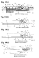
- Fig. 10(a) is a schematic view showing the latch 4 and a surrounding portion thereof when the latch 4 is in the standby position.
- Fig. 10(b) is a schematic view showing the latch 4 and the surrounding portion thereof when the latch 4 is in the standby position.
- Fig. 10(c) is a schematic view showing the latch 4 and the surrounding portion thereof when the latch 4 is switched from the standby position to the draw-in position.
- Fig. 10(d) is a pattern diagram showing a process wherein an urging force is being accumulated in a coil spring 3.
- Fig. 10(b) is a schematic view showing the latch 4 and the surrounding portion thereof when the latch 4 is in the standby position.
- Fig. 10(c) is a schematic view showing the latch 4 and the surrounding portion thereof when the latch 4 is switched from the standby position to the draw-in position.
- Fig. 10(d) is a pattern diagram showing a process wherein an urging force is being accumulated in a coil spring 3.
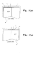
- FIG. 11(a) is a drawing showing a condition wherein the slide assist device according to the present embodiment is applied to a main body 7 and a sliding portion of a door A (a mobile body).
- Fig. 11(b) is a drawing showing a condition wherein the slide assist device according to the present embodiment is applied to the main body 7 and the sliding portion of the door A (the mobile body).
- Fig. 11(c) is a perspective view showing a structural example of a projecting body 8 (an actuating member).
- the slide assist device comprises the draw-in unit 6 attached to one of the main body 7 or the mobile body (hereinafter, explained in an example of the door A) such as a sliding door, a door, and the like; and the projecting body 8 attached to the other of the main body 7 or the door A.
- the door A is one example of the mobile body which is an attachment object of the slide assist device
- the projecting body 8 is one example of the actuating member in the present invention.
- the first structure is a case where the draw-in unit 6 and two projecting bodies 8 as a pair are used.
- the draw-in unit 6 disposes a pair of the sliders 2A and 2B which is slid in a moving direction toward and away from each other relative to the case 1; the coil spring 3 urging in a direction of moving both the sliders 2A and 2B close to each other; a braking device 5 putting a brake on a sliding speed of the sliders 2A and 2B; and a pair of the latches 4 rotatably supported respectively in each slider 2A and 2B, and releasably locked in a corresponding portion inside the case 1 so as to be capable of holding both the sliders 2A and 2B in a separated state.
- the coil spring 3 is one example of the urging device in the present invention.
- a second structure is a case wherein as the mobile body, for example, the double-door-type door (the sliding door) A and a door B respectively slide relative to a corresponding opening portion of the main body 7. Structural members of the draw-in unit 6 corresponding to one door A and the draw-in unit 6 corresponding to the other door B are embedded in the common case 1.
- the draw-in unit 6 there is a unit of the right-and-left sliders 2A and 2B which are slid in the direction of moving toward and away from each other; the coil spring 3 urging both the sliders 2A and 2B in the direction of moving close to each other; and a pair of the latches 4 pivotally supported respectively in each slider 2A and 2B, and also releasably locked in a case 1 side so as to be capable of holding both the sliders 2A and 2B in the separated state.
- the draw-in unit 6 has the structure wherein two pairs of the above are disposed relative to the same case 1. Since an explanation of the above can be easily inferred from the following embodiment, the explanation is omitted.
- a third structure is a case where the mobile body is drawn in only in one direction.
- the draw-in unit 6 is the most simplified structure in which one of the sliders 2A and 2B in Fig. 1(a) is omitted, one end of the coil spring 3 is locked in the slider, and also the other end is locked in a case side, and as necessary, one end of the braking device 5 is locked in the slider, and also the other end is locked in the case 1 side. Since an explanation of the above can be easily inferred from the following embodiment, the explanation is also omitted.
- the case 1 of the draw-in unit 6 is a slender part with an approximately cuboid shape, and includes an internal space 10 divided by a lower surface 11, both side surfaces 12, and right-and-left end portions 13a. On an upper side of the internal space 10, there is provided an opening. Also, the above-mentioned opening is covered by the cover 15. Also, on right and left of the internal space 10 in the case 1, there are provided attachment portions 10a for attaching the case 1 to the main body 7. Also, the end portions 13a divide the internal space 10 on an outer side than end portions 13 in a longitudinal direction of the case 1, and on an inner surface of the end portions 13a, there abut elongation portions 3b of the coil spring 3.
- a guide groove 11a is a shallow concave groove formed along an inner side of one side surface 12, and positions the sliders 2A and 2B, and one portion of the coil spring 3.
- Guide grooves 11d are concave portions which facilitate a cylinder 50 structuring a piston damper as the braking device 5 to slide inside the case 1.
- the reference numeral 11e represents a guide groove which fits into a convex portion 48 provided on a lower surface of the latch 4.
- the cover 15 includes a slider guide groove 19b provided between a rib 19a and a rib 19a formed along the longitudinal direction in an intermediate portion in the width direction; and an approximately concave latch guide portion 16 provided in the middle of right and left.
- the guide portion 16 includes a straight groove 16a extending to the right and left, and locking grooves 16b with an approximately L shape provided on both sides of the straight groove 16a.
- both side surfaces 12 of the case 1 and both sides 17 on a cover side there are provided hook-like locking portions 12a and concave engaging portions 17a mutually engaging when the cover 15 is disposed in the space portion 10 with a plurality of pairs.
- the attachment portions 10a on the case side and right-and-left end surfaces 18 on the cover side there are provided a concave locking portion 10c and a convex engaging portion 18a, and a convex locking portion 10d and a concave engaging portion 18b, which mutually engage when the cover 15 is disposed in the space portion 10. Then, in the example, the cover 15 is placed in the case 1 through engagements of the above-mentioned portions.
- the right-and-left attachment portions 10a have a cross-section of an inverted concave shape in the width direction, and the projecting body 8 can slide along the guide hole 11a from an inverted concave portion thereof.
- the sliders 2A and 2B have a block shape made of resin, and are disposed in a space between the lower surface 11 of the case 1 and the cover 15.
- the braking device 5 since a piston-type damper is used, shapes of the sliders 2A and 2B differ. However, in such a case where a rotary damper is used as the braking device, the sliders 2A and 2B can also have the same shape.
- Connecting portions 21 and 31 for the braking device form one portion of an upper surface 2a and a lower surface 2b, and also include ribs 22 and 32 provided on the upper surface 2a and extending to right and left. Also, there include convex portions 23 and 33 provided in four corners of an approximately intermediate portion of the lower surface 2b. Also, there include guide portions 24 and 34 with an arc-like cross-section provided in parallel to one side, i.e., to the connecting portions 21 and 31, and guiding the braking device 5; and spring placement portions 25 and 35 provided along a longitudinal direction on a lower surface side on the other side.
- concave engaging portions 26 and 36 provided on one end side of each spring placement portion 25 and 35, and locking corresponding end portions 3a of the coil spring 3.
- latch placement portions 20 and 30 located on spring placement portions 25 and 35 sides, and formed in a concave shape in one portion on a lower side.
- escape grooves 28 and 38, and support grooves 27 and 37 provided on an upper wall portion dividing each latch placement portion 20 and 30; and pivotally supporting axis holes 20a and 30a.
- the engaging portion 26 of the slider 2A is an approximately short-formed wall surface vertically protruding relative to the spring placement portion 25.
- the engaging portion 36 of the slider 2B is an approximately short-formed wall surface vertically protruding relative to the spring placement portion 35. The engaging portion 26 of the slider 2A and the engaging portion 36 of the slider 2B abut against the end portions 3a of the coil spring 3.
- the connecting portion 21 includes claws 21a and positioning protrusions 21b, provided on both sides; a housing portion 21d including a window 21c opening in a horizontal direction; and the attachment member 29 which is placed in such a way as to cover the housing portion 21d.
- the attachment member 29 is structured by an approximately short-formed planar portion, and lateral face portions vertically extending relative to the planar portion from both sides of the planar portion. Then, on the aforementioned lateral face portions of the attachment member 29, there are formed engaging holes 29a engaging with the claws 21a of the connecting portion 21; and concave portions 29b engaging with the protrusions 21b of the connecting portion 21.
- the connecting portion 31 of the slider 2B includes an approximately U-shaped clamp portion 34a provided by maintaining a gap 34b between an inner end surface and the clamp portion 34a.
- the axis holes 20a and 30a are provided near end portions of the sliders 2A and 2B, and pass through in an up-and-down direction.
- a cross-sectional shape of the axis holes 20a and 30a has the approximately same shape as a cross-sectional shape of an axis portion 43 of the later-mentioned latch 4. Namely, as shown in Fig. 8 , the cross-sectional shape of the axis holes 20a and 30a has a shape in which one portion of a circular form is notched. Therefore, although most of an inner surface of the axis holes 20a and 30a has an approximately cylindrical form, there is provided a planar portion as a positional control surface 20b in one portion thereof.
- the support grooves 27 and 37 are located on a concentric circle as the axis holes 20a and 30a, are notched in an arc shape from one side, and also include step differences 27a and 37a which become receiving faces provided along an upper edge.
- the step differences 27a and 37a structure a control device 9, which maintains the latch 4 horizontally so that the latch 4 does not tilt up and down, together with a head portion 41b of a support axis 41 on the later-mentioned latch side.
- the escape grooves 28 and 38 are located on a concentric circle as the axis holes 20a and 30a, are notched in an arc shape from one side in a state wherein a groove width is enlarged more than the aforementioned support axis, and include step differences 28a and 38a which become receiving faces provided along an outside upper edge which is separated from the support axis; and a resistance-imparting portion 28b provided on each step difference 27a and 37a.
- the step differences 28a and 38a receive an end portion 45 of the latch 4 from underneath in a state wherein the axis portion 43 of the later-mentioned latch 4 fits into the axis hole 20a or the axis hole 30a so as to be pivotally supported in the sliders 2A and 2B.
- the resistance-imparting portion 28b is a convex portion protruded on the step differences 28a and 38a thereof, and acts as a resistance (an increase portion) or a frictional force (the increase portion) when the latch 4 is turned as a supporting point of a pivotal support portion relative to the sliders 2A and 2B so as to stably hold the latch 4 in the standby position of Fig. 3(a) , and to prevent a tracing protrusion 46 from being abruptly unlocked from the aforementioned locking groove 16b.
- the above-mentioned resistance-imparting portion 28b may be formed in a concave-convex portion other than the convex portion, and furthermore, the resistance-imparting portion 28b may be provided on a lower surface of an end of the latch 4 in place of an upper surface of the step differences 28a and 38a, or together with the upper surface of the step differences 28a and 38a.
- the latch 4 used for the slider 2A and the latch 4 used for the slider 2B are bilaterally symmetric mutually.
- the latch 4 is a resin molded body with a thickness size which can easily fit in the latch placement portions 20 and 30, and integrally forms a support portion 40 pivotally supporting to sliders 2A and 2B sides; an engaging portion 42 provided on one side of the support portion 40, and engaging with/disengaging from the projecting body 8, which is the actuating member, at a normal time; and an assist engaging device 47 located on a lower surface side of the latch 4, and provided on an end portion 45 side rather than the engaging portion 42.
- the support portion 40 includes a pivotally supporting axis portion 43 located on an upper surface side, and provided to protrude on an end portion side; a suspending support axis 41 provided to protrude near the center; and the tracing protrusion 46 provided to protrude on an end side which is separated from the axis portion 43.
- a pivotally supporting axis portion 43 located on an upper surface side, and provided to protrude on an end portion side; a suspending support axis 41 provided to protrude near the center; and the tracing protrusion 46 provided to protrude on an end side which is separated from the axis portion 43.
- the axis portion 43 there is formed a flat surface portion 43a along an axis direction, so that an outer shape of a cross section of the axis portion 43 is not a complete circular form, and includes an arc portion and a straight portion.
- the axis portion 43 of the latch 4 when the axis portion 43 of the latch 4 is turned from the aforementioned fitted state, the axis portion 43 deviates for a predetermined angle from a state wherein the positional control surface 20b of an axis hole 20a side and the flat surface 43a face approximately in parallel as mentioned above.
- the fitting between the axis hole 30a of the slider 2B and the axis portion 43 of the latch 4 is also approximately the same as the fitted state between the slider 2A and the latch 4.
- the above-mentioned cross-sectional shapes may have, for example, an H cut. Namely, in the standby position of the latch 4 shown in Fig.
- the structure may be that the positional control surface 20b and the flat surface 43a of the axis holes 20a and 30a in the sliders 2A and 2B become the fitted state of facing approximately in parallel, so that the tracing protrusion 46 becomes difficult to deviate from the locking groove 16b, and also that when the latch 4 is switched to the draw-in position of Fig. 3(b) from the standby position (when the tracing protrusion 46 enters into the straight groove 16a from the aforementioned locking groove 16b), accompanied by the aforementioned fitted state that is released, a large resistance force acts.
- the cross-sectional shape of the axis portion 43 of the latch 4 and the cross-sectional shape of the axis holes 20a and 30a of the sliders 2A and 2B have the shape as mentioned above so as to be capable of reducing an abnormal noise which can easily occur when the latch 4 is switched to the draw-in position from the standby position.
- the support axis 41 includes a neck portion 41a slidably inserted and passed through the support groove 27 or 37, and the head portion 41b forming the diameter larger than that of the neck portion 41a around a top of the neck portion.
- the head portion 41b structures the control device 9 together with the support groove 27 or 37, and retains the neck portion 41a in a state being inserted and passed through the support groove 27 or 37.
- the protrusion 46 is formed higher than the axis portion 43 and the support axis 41, and in a state wherein the latch 4 is pivotally supported rotatably in each slider 2A and 2B, the latch 4 fits into the guide portion 16 on the cover side, slides along the straight groove 16a, and engages with the locking groove 16b so as to lock sliding of the latch 4 (and the sliders 2A and 2B).
- the assist engaging device 47 engages with the projecting body 8 when the latch 4 has come to the draw-in position by a mis-actuation so as to be capable of switching the latch 4 from the draw-in position to the standby position.
- the assist engaging device 47 has a step-like shape whose end side is widely depressed on the lower surface side of the latch 4, and is structured by a slope-face guide portion 45a on an end side which guides the projecting body 8, and a concave portion 47a continuous with the slope-face guide portion 45a, and deepening one step.
- the slope-face guide portion 45a is a taper which lowers as the slope-face guide portion 45a goes to the end.
- the projecting body 8 when the projecting body 8 abuts upward against the slope-face guide portion 45a, the projecting body 8 slides while reducing a protruding amount, and when the projecting body 8 enters into the concave portion 47a, the projecting body 8 increases the protruding amount again so as to maintain an engagement with the concave portion 47a.
- the coil spring 3 is a compression coil spring.
- the small diameter end portions 3a In a position deviated slightly toward the center rather than end surfaces of both right and left ends in the coil spring 3, there are formed the small diameter end portions 3a in which a diameter of a cross-section is narrowed down smaller than a center portion of the coil spring 3.
- the elongation portions 3b On end surface sides rather than the small diameter end portions 3a, there are provided the elongation portions 3b having an approximately equal diameter of the cross-section to that of the center portion of the coil spring 3.
- the elongation portions 3b act as a buffering portion in the present invention, and a coil wind is formed more roughly than the small diameter end portions 3a.
- the piston-type damper may be a publicly known piston-type damper (for example, see Japanese Unexamined Patent Publication No. 2006-29564 and the like), and may have a structure of including the cylinder 50, and a piston rod 51 gently protruding and entering with respect to the cylinder 50; of gently driving relative to the cylinder 50 wherein the piston rod 51 is fixed; or of gently driving relative to the piston rod 51 wherein the cylinder 50 is fixed.
- the cylinder 50 includes a neck-like locking groove 50a on an outer circumference of a back end
- the piston rod 51 includes a neck-like locking groove 51a on an outer circumference of a front end.
- the protruding body 8 is one example of the actuating member in the present invention, and has a structure freely protruding and entering with respect to the door A, which is one example of the mobile body, through the urging force, i.e., the structure of reducing the protruding amount against the urging force when the protruding body 8 receives a load.
- the present example is described in Japanese Unexamined Patent Publication No.
- the projecting body 8 is not limited to the above, and the projecting body 8 may have a guide axis structure which is disclosed in, for example, Japanese Unexamined Patent Publication No. 2007-107301 , or a structure similar to the above.
- each above-mentioned member is assembled as follows. Namely, first, after each latch 4 is pivotally supported in the sliders 2A and 2B, both the sliders 2A and 2B are connected through the piston-type damper, which is the braking device 5, and the coil spring 3. Next, the above members are assembled to the case 1, and the cover 15 is attached to the case 1 so as to become the draw-in unit 6.
- each latch 4 is rotatably supported relative to the sliders 2A and 2B by fitting of the axis portion 43 and the axis hole 20a, or of the axis portion 43 and the axis hole 30a.
- the support axis 41 is supported in a suspending state relative to the step difference 27a of the arc-like support groove 27, or to the step difference 37a of the support groove 37;
- the protrusion 46 protrudes to an upper side of the sliders 2A and 2B by passing through the escape groove 28 or the escape groove 38; and the end portion 45 is supported so as to be received in a flange-like receiving portion 28a or a receiving portion 38a provided on an inner side edge of the escape groove.
- a fixing ring 52 which is a temporary fixing member, engages with the locking groove 51a on the outer circumference of the rod front end, so that the piston rod 51 is temporarily fixed into the housing portion 21d of the connecting portion 21 through the fixing ring 52.
- the attachment member 29 is placed relative to the connecting portion 21 by engagements between the upper and lower claws 21a and the engaging holes 29a, and engagements between the protrusions 21b and the concave portions 29b, so that the piston rod 51 is firmly fixed from a temporary fixed state, and the position is reliably fixed. Only by matching the locking groove 50a on the aforementioned cylinder side to the gap 34b and by pressing, the cylinder 50 is engaged with and is connected to the clamp portion 34a relative to the connecting portion 31 of the slider 2B.
- each elongation portion 3b protrudes only for a predetermined size more than a corresponding end of the sliders.
- the latch 4 and the sliders 2A and 2B pivotally supporting the latch 4 are disposed relative to the case 1 together with the braking device 5 and the coil spring 3.
- the convex portions 23 or 33 on the lower surface of each slider 2A and 2B fit into the guide grooves 11b of the case 1; the rib 22 or 32 on the upper surface of each slider fits into the guide groove 19b of the cover 15; and lower surface portions structuring the engaging portions 26 and 36 of each slider 2A and 2B are slidably fitted into the guide groove 11c.
- the protrusion 46 is fitted into the guide portion 16 of the case 1 from the escape grooves 28 and 38 of the sliders 2A and 2B, and the latch 4 is switched between the draw-in position which is slid along the straight groove 16a accompanied by sliding of the sliders, and the standby position which enters into the locking groove 16b from the straight groove 16a and is locked.
- the convex portion 48 on the lower surface is consistently fitted into the guide groove 11e on the lower surface of the case 1 so as to allow the latch 4 to stably follow even rapid sliding of the corresponding slider.
- Fig. 10(a) shows a left side portion in the draw-in unit 6, i.e., the stand-by position (a state wherein the protrusion 46 on a latch side is engaged with the locking groove 16b of the guide portion 16 on the cover side) of the latch 4 on the slider 2A side together with the projecting body 8 which is the actuating member.
- Fig. 10(b) shows the same aspect as that of Fig. 10(a) by showing only the slider 2A with imaginary lines so that a relationship of the members can be easily understood.
- the coil spring 3 is stretched, and the urging force has been accumulated.
- the elongation portion 3b on the left side abuts against the end portion 13a of the case 1.
- there is an actuation characteristic as follows.
- the cross-sectional shape of the axis hole 20a has a shape in which one portion of a circular arc is notched in a linear fashion. Therefore, although most of the inner surface of the axis hole 20a has the approximately cylindrical form, there is provided the planar portion as the positional control surface 20b in one portion thereof. Also, the cross-sectional shape of the axis portion 43 has the shape in which one portion of the circular arc is notched in the linear fashion as well. Therefore, although most of an outer surface of the axis portion 43 has the approximately cylindrical form, there is provided the planar portion 43a in one portion thereof.
- Fig. 10(c) shows a state wherein the latch has been switched to the draw-in position.
- the latch 4 when the latch 4 is in the standby position as shown in Fig. 10(b) , the door A has been moved in a right direction (a closing direction) from the left in Fig. 11(a) , and the projecting body 8 of the door hits against a corresponding portion of the engaging portion 42.
- the latch 4 is rotated counterclockwise at a supporting point of the axis portion 43 by stress thereof, and the protrusion 46 is unlocked from the locking groove 16b so as to fit into the straight groove 16a, and the latch 4 is switched to the draw-in position wherein the projecting body 8 has been engaged with the engaging portion 42.
- the slider 2A is drawn into the slider 2B side by the urging force of the urging device 3 together with the latch 4 so as to switch the door to a closed position.
- the door receives braking of the aforementioned braking device 5 so as to be gently slid.
- Fig. 10(d) assumes a state wherein the door A has been operated to slide in an open direction from the closed position.
- the slider 2A is slid to a left side through the projecting body 8 engaged with the engaging portion 42 of the latch 4 which is in the drawn-in position.
- the door is moved to the left further, and reaches the locking groove 16b on the left side as in the case of Fig.
Landscapes
- Engineering & Computer Science (AREA)
- Mechanical Engineering (AREA)
- Closing And Opening Devices For Wings, And Checks For Wings (AREA)
- Vehicle Step Arrangements And Article Storage (AREA)
Applications Claiming Priority (2)
| Application Number | Priority Date | Filing Date | Title |
|---|---|---|---|
| JP2010060234A JP5433466B2 (ja) | 2010-03-17 | 2010-03-17 | 摺動補助装置 |
| PCT/JP2011/056353 WO2011115198A1 (fr) | 2010-03-17 | 2011-03-17 | Dispositif de facilitation de coulissement |
Publications (1)
| Publication Number | Publication Date |
|---|---|
| EP2549042A1 true EP2549042A1 (fr) | 2013-01-23 |
Family
ID=44649281
Family Applications (1)
| Application Number | Title | Priority Date | Filing Date |
|---|---|---|---|
| EP11756382A Withdrawn EP2549042A1 (fr) | 2010-03-17 | 2011-03-17 | Dispositif de facilitation de coulissement |
Country Status (6)
| Country | Link |
|---|---|
| US (1) | US8671520B2 (fr) |
| EP (1) | EP2549042A1 (fr) |
| JP (1) | JP5433466B2 (fr) |
| KR (1) | KR101409045B1 (fr) |
| CN (1) | CN102822436B (fr) |
| WO (1) | WO2011115198A1 (fr) |
Cited By (2)
| Publication number | Priority date | Publication date | Assignee | Title |
|---|---|---|---|---|
| EP4343097A4 (fr) * | 2022-06-29 | 2024-11-27 | Guangdong OPK Smart Home Technology Co., Ltd. | Nouvel amortisseur pour porte et fenêtre coulissantes |
| US20250033775A1 (en) * | 2021-12-07 | 2025-01-30 | Safran Seats | Partition for aircraft seat arrangement with sliding door and associated aircraft seat arrangement |
Families Citing this family (18)
| Publication number | Priority date | Publication date | Assignee | Title |
|---|---|---|---|---|
| JP2011196015A (ja) * | 2010-03-17 | 2011-10-06 | Nifco Inc | 摺動補助装置 |
| JP5433466B2 (ja) * | 2010-03-17 | 2014-03-05 | 株式会社ニフコ | 摺動補助装置 |
| ITMI20121718A1 (it) * | 2012-10-12 | 2014-04-13 | Salice Arturo Spa | Mobile con almeno un cassetto o simile |
| CN103874368A (zh) * | 2012-12-12 | 2014-06-18 | 富泰华工业(深圳)有限公司 | 电子装置 |
| WO2014169771A1 (fr) * | 2013-04-15 | 2014-10-23 | Xu Jiangde | Dispositif de roue supérieure anti-rebondissement à amortissement à double tuyau |
| DE102013104886A1 (de) * | 2013-05-13 | 2014-11-13 | Karl Simon Gmbh & Co. Kg | Schiebeanordnung |
| ES2627883T3 (es) * | 2013-07-26 | 2017-07-31 | Hawa Sliding Solutions Ag | Mecanismo de rodadura ajustable y dispositivo deslizante |
| DE102013114309A1 (de) * | 2013-12-18 | 2015-06-18 | Paul Hettich Gmbh & Co. Kg | Einzugs- und Dämpfungseinheit für ein Schiebeelement |
| DE102015003415B3 (de) * | 2015-03-17 | 2016-02-25 | Günther Zimmer | Beschleunigungs- und Verzögerungsvorrichtung mit geräuscharmer Bewegung |
| US9863178B2 (en) * | 2015-08-21 | 2018-01-09 | Weider Metal Inc. | Two-way soft closing device for a sliding door and soft closing activation trigger assembly thereof |
| US11008775B2 (en) | 2015-12-03 | 2021-05-18 | Lawrence E Chaffin | Lift glide door lock assembly and lift glide window lock assembly and dual lift glide door lock assembly and dual lift glide window lock assembly |
| US10526829B2 (en) | 2015-12-03 | 2020-01-07 | Lawrence E Chaffin | Lift glide door lock assembly and lift glide window lock assembly |
| CN105507720B (zh) * | 2016-01-18 | 2018-04-06 | 王胜利 | 一种双向阻尼器及其应用的移动门 |
| US10591728B2 (en) * | 2016-03-02 | 2020-03-17 | Mentor Acquisition One, Llc | Optical systems for head-worn computers |
| WO2017192112A1 (fr) * | 2016-06-30 | 2017-11-09 | Rollmech Automotive Sanayi Ve Ticaret Anonim Sirketi | Butoir de porte coulissante |
| US10292494B1 (en) * | 2017-07-03 | 2019-05-21 | Nan Jeun International Co., Ltd. | Slide rail self-return mechanism |
| TWI640276B (zh) * | 2017-09-22 | 2018-11-11 | 川湖科技股份有限公司 | 滑軌總成及其驅動機構 |
| TWI693041B (zh) * | 2018-04-30 | 2020-05-11 | 川湖科技股份有限公司 | 滑軌總成 |
Family Cites Families (71)
| Publication number | Priority date | Publication date | Assignee | Title |
|---|---|---|---|---|
| US1174210A (en) * | 1915-06-16 | 1916-03-07 | Benjamin Wexler | Door-check. |
| US2601604A (en) * | 1950-10-17 | 1952-06-24 | Wade O Ford | Automatic control for swinging doors |
| US2882112A (en) * | 1956-12-04 | 1959-04-14 | Haskell Mfg Co Inc | Drawer lock |
| US3358318A (en) * | 1965-03-05 | 1967-12-19 | Roto Swing Door Co Inc | Door check |
| US3637247A (en) * | 1970-07-10 | 1972-01-25 | Peter M Manion | Locking bar for horizontally sliding building closure assemblies |
| US4656781A (en) * | 1985-02-22 | 1987-04-14 | Ardco, Inc. | Sliding door assembly |
| US4675938A (en) * | 1985-11-06 | 1987-06-30 | Bundschuh Robert L | Retraction device for doors or windows |
| DE9007365U1 (de) * | 1990-06-26 | 1991-07-11 | Karl Lautenschläger GmbH & Co KG Möbelbeschlagfabrik, 6107 Reinheim | Einzugsautomatik für Schubladen-Ausziehführungen |
| AT401717B (de) * | 1993-06-23 | 1996-11-25 | Blum Gmbh Julius | Schliessvorrichtung für schubladen |
| US5529148A (en) * | 1993-08-24 | 1996-06-25 | O'leary; Thomas M. | Automatic brake and hold mechanism for sliding rods |
| GB9322491D0 (en) * | 1993-11-01 | 1993-12-22 | Christ Manfred | Adjustable delayed-action door closer |
| AT407602B (de) * | 1994-08-31 | 2001-05-25 | Alfit Ag | Einzugsvorrichtung für schubladen |
| US5832562A (en) * | 1995-10-25 | 1998-11-10 | Luca; Valentin | Door closer |
| US5842255A (en) * | 1995-10-25 | 1998-12-01 | Luca; Valentin | Door closers with automatic latching or/and delayed action |
| DE19626831C1 (de) * | 1996-07-04 | 1998-01-08 | Dorma Gmbh & Co Kg | Türschließer zur Erzeugung eines Übersetzungssprunges während der Schließphase |
| US5967587A (en) * | 1997-03-18 | 1999-10-19 | Prince Corporation | Sliding visor |
| US6971729B1 (en) * | 2000-05-01 | 2005-12-06 | Accuride International, Inc. | Self-closing slide |
| TW508040U (en) * | 2001-09-05 | 2002-10-21 | Hinge Basestrong Co Ltd | Radial pressing structure of rotation shaft |
| US6848759B2 (en) * | 2002-04-03 | 2005-02-01 | Illinois Tool Works Inc. | Self-closing slide mechanism with damping |
| ITMC20030144A1 (it) * | 2003-12-05 | 2005-06-06 | Compagnucci Spa Ora Compagnucci Ho Lding Spa | Dispositivo per la chiusura automatica ed ammortizzata dei cassetti e delle strutture estraibili per mobili. |
| JP4685380B2 (ja) | 2004-07-21 | 2011-05-18 | 株式会社ニフコ | 移動体の衝撃吸収装置 |
| JP4459679B2 (ja) * | 2004-03-30 | 2010-04-28 | 株式会社ニフコ | 摺動補助装置 |
| GB2415014B (en) * | 2004-06-12 | 2008-10-22 | Heath Samuel & Sons Plc | Door closer |
| JP4446823B2 (ja) * | 2004-07-21 | 2010-04-07 | 株式会社ニフコ | 摺動補助装置 |
| JP4446824B2 (ja) * | 2004-07-21 | 2010-04-07 | 株式会社ニフコ | スライド補助装置 |
| US20060021189A1 (en) * | 2004-07-30 | 2006-02-02 | Johnson Loring M | Door closer |
| DE202005009860U1 (de) * | 2004-12-17 | 2006-04-20 | Alfit Ag | Schließ- und Öffnungsvorrichtung für Schubladen |
| US20060272129A1 (en) * | 2005-06-04 | 2006-12-07 | Torqmaster, Inc. | Friction hinge with viscous damping |
| JP2007107301A (ja) | 2005-10-14 | 2007-04-26 | Murakoshi Mfg Corp | 引戸などのガイド装置 |
| CN101305150B (zh) * | 2005-11-08 | 2012-02-29 | 株式会社利富高 | 引入机构 |
| JP2007182714A (ja) | 2006-01-10 | 2007-07-19 | Tsuchikawa Zenji | 引戸装置 |
| US7815267B1 (en) * | 2006-09-15 | 2010-10-19 | Gus Frousiakis | Drawer slide closure apparatus |
| JP5004329B2 (ja) | 2006-10-30 | 2012-08-22 | 株式会社ニフコ | ガラスホルダー |
| JP5093881B2 (ja) | 2006-11-13 | 2012-12-12 | 株式会社ニフコ | 摺動補助機構及び引込ユニット |
| JP4970117B2 (ja) * | 2006-11-30 | 2012-07-04 | 株式会社ニフコ | 可動体の自走往動機構 |
| CN200991010Y (zh) * | 2006-12-25 | 2007-12-19 | 谢银旺 | 抽屉缓冲器及带抽屉缓冲器的抽屉滑轨 |
| TWI321996B (en) * | 2007-02-17 | 2010-03-21 | King Slide Works Co Ltd | Slide assembly having an automatic retractable device |
| US7708357B2 (en) * | 2007-03-20 | 2010-05-04 | Weon-Dong Cho | Automatic locking apparatus used in guide rail for drawer |
| JP5020148B2 (ja) * | 2007-04-06 | 2012-09-05 | トゥルース ハードウェア コーポレイション | 引き戸の二重ロック |
| TWI321995B (en) * | 2007-05-15 | 2010-03-21 | King Slide Works Co Ltd | Drawer slide assembly with an undermount drawer slide |
| US8083304B2 (en) * | 2007-07-18 | 2011-12-27 | Accuride International, Inc. | Self closing mechanism for drawer slides |
| CN201087610Y (zh) * | 2007-09-14 | 2008-07-16 | 李昌玉 | 中控锁齿轮传动机构 |
| DE202008003328U1 (de) * | 2007-10-02 | 2009-02-12 | Paul Hettich Gmbh & Co. Kg | Auszugsführung mit einer Selbsteinzugsvorrichtung |
| DE102008021458A1 (de) * | 2008-04-29 | 2010-01-07 | Zimmer, Günther | Beschleunigungsvorrichtung mit zwei Energiespeichern |
| TWI367083B (en) * | 2008-05-07 | 2012-07-01 | King Slide Works Co Ltd | Retraction mechanism for a drawer |
| JP5294714B2 (ja) * | 2008-06-06 | 2013-09-18 | 株式会社ニフコ | 摺動補助機構 |
| CN102065726A (zh) * | 2008-07-24 | 2011-05-18 | 格拉斯美国公司 | 用于抽屉滑动装置的控制机构 |
| TWM349712U (en) * | 2008-07-30 | 2009-02-01 | Nan Juen Int Co Ltd | Automatic returning slide device |
| US20100031469A1 (en) * | 2008-08-07 | 2010-02-11 | Chou-Chih Chiang | Damped Closing Mechanism for automatic Shutting Pull Door |
| JP5176795B2 (ja) | 2008-09-05 | 2013-04-03 | パナソニック株式会社 | 給湯装置 |
| US8060983B2 (en) * | 2008-09-25 | 2011-11-22 | Bortoluzzi Mobili S.R.L. | Device for cushioning an opening and closing movement of sliding shutters |
| ES2397814T3 (es) * | 2008-10-13 | 2013-03-11 | Arturo Salice S.P.A. | Dispositivo de abertura y cierre automático, particularmente para una parte móvil de un mueble |
| JP2010112012A (ja) * | 2008-11-04 | 2010-05-20 | Nifco Inc | 可動体の往動機構 |
| TWI392465B (zh) * | 2008-11-20 | 2013-04-11 | King Slide Works Co Ltd | 用於滑軌組件之自動回歸裝置 |
| IT1392184B1 (it) * | 2008-12-12 | 2012-02-22 | Salice Arturo Spa | Dispositivo di apertura e chiusura di una parte spostabile di un mobile |
| EP2424404B1 (fr) * | 2009-04-27 | 2016-09-21 | Accuride International Inc. | Mécanisme de coulissement et de verrouillage de tiroir |
| JP2011001781A (ja) | 2009-06-19 | 2011-01-06 | Nifco Inc | 移動体のガイド装置 |
| JP2011006872A (ja) * | 2009-06-24 | 2011-01-13 | Nifco Inc | 摺動補助機構及び引込ユニット |
| US8079653B2 (en) * | 2009-07-07 | 2011-12-20 | Nan Juen International Co., Ltd | Sliding track assembly |
| US8205951B2 (en) * | 2009-11-04 | 2012-06-26 | Knape & Vogt Manufacturing Company | Closing device for drawers |
| US8307497B2 (en) * | 2010-01-14 | 2012-11-13 | Door & Window Hardware Co. | Soft-closing device for a sliding door |
| US8240788B2 (en) * | 2010-03-04 | 2012-08-14 | Sun Chain Metal Industry Co., Ltd. | Hidden self-closing drawer slide assembly |
| JP5433466B2 (ja) * | 2010-03-17 | 2014-03-05 | 株式会社ニフコ | 摺動補助装置 |
| JP2011196015A (ja) * | 2010-03-17 | 2011-10-06 | Nifco Inc | 摺動補助装置 |
| MY155806A (en) * | 2010-07-29 | 2015-11-30 | Harn Marketing Sdn Bhd | Drawer guide rail system |
| PL2746508T3 (pl) * | 2010-09-06 | 2019-05-31 | In & Tec Srl | Zawias zamykający drzwi, w szczególności do drzwi szklanych |
| US8469468B2 (en) * | 2010-09-10 | 2013-06-25 | King Slide Works Co., Ltd. | Slide assembly with buffering device |
| TWI361862B (en) * | 2011-02-15 | 2012-04-11 | Yuan Deng Metals Ind Co Ltd | Stress-absorbing shaft structure |
| ITMI20110517A1 (it) * | 2011-03-30 | 2012-10-01 | Salice Arturo Spa | Dispositivo di ritegno per dispositivo di apertura e chiusura automatica per parte spostabile di mobile |
| US8402606B1 (en) * | 2011-10-18 | 2013-03-26 | Patrick Tsai | Door closer with buffer mechanism for a sliding door |
| JP5497833B2 (ja) * | 2012-05-10 | 2014-05-21 | 株式会社ニフコ | 摺動補助機構 |
-
2010
- 2010-03-17 JP JP2010060234A patent/JP5433466B2/ja active Active
-
2011
- 2011-03-17 EP EP11756382A patent/EP2549042A1/fr not_active Withdrawn
- 2011-03-17 CN CN201180014353.1A patent/CN102822436B/zh not_active Expired - Fee Related
- 2011-03-17 WO PCT/JP2011/056353 patent/WO2011115198A1/fr not_active Ceased
- 2011-03-17 KR KR1020127023703A patent/KR101409045B1/ko not_active Expired - Fee Related
- 2011-03-17 US US13/634,115 patent/US8671520B2/en not_active Expired - Fee Related
Non-Patent Citations (1)
| Title |
|---|
| See references of WO2011115198A1 * |
Cited By (2)
| Publication number | Priority date | Publication date | Assignee | Title |
|---|---|---|---|---|
| US20250033775A1 (en) * | 2021-12-07 | 2025-01-30 | Safran Seats | Partition for aircraft seat arrangement with sliding door and associated aircraft seat arrangement |
| EP4343097A4 (fr) * | 2022-06-29 | 2024-11-27 | Guangdong OPK Smart Home Technology Co., Ltd. | Nouvel amortisseur pour porte et fenêtre coulissantes |
Also Published As
| Publication number | Publication date |
|---|---|
| US8671520B2 (en) | 2014-03-18 |
| WO2011115198A1 (fr) | 2011-09-22 |
| US20130019438A1 (en) | 2013-01-24 |
| JP2011196014A (ja) | 2011-10-06 |
| JP5433466B2 (ja) | 2014-03-05 |
| CN102822436A (zh) | 2012-12-12 |
| CN102822436B (zh) | 2016-06-22 |
| KR101409045B1 (ko) | 2014-06-18 |
| KR20120125539A (ko) | 2012-11-15 |
Similar Documents
| Publication | Publication Date | Title |
|---|---|---|
| EP2549042A1 (fr) | Dispositif de facilitation de coulissement | |
| EP2549041A1 (fr) | Dispositif de facilitation du coulissement | |
| KR101971950B1 (ko) | 멀티 링크 힌지 장치 | |
| US8888200B2 (en) | Slide assist mechanism and draw-in unit | |
| RU2594867C2 (ru) | Шарнир | |
| JP2010161796A (ja) | スライド型携帯電話用のスライダー組立体及びスライド型携帯電話 | |
| KR101559676B1 (ko) | 댐퍼수납부가 확장된 슬라이더 완충장치 | |
| KR20100064188A (ko) | 도어용 슬라이더 장착 브래킷 | |
| KR102492726B1 (ko) | 도어 스토퍼 | |
| JP4231223B2 (ja) | 引戸用取手 | |
| JP2017150147A (ja) | 施錠装置 | |
| JP4838082B2 (ja) | ドアクローザー | |
| KR102048626B1 (ko) | 반자동 연동형 도어 시스템 | |
| JP5576255B2 (ja) | 開閉体閉止装置 | |
| EP3407444A1 (fr) | Mécanisme d'ouverture et de fermeture du couvercle d'un logement | |
| JP4693535B2 (ja) | 施錠装置 | |
| KR101242448B1 (ko) | 슬라이드식 창문용 개폐기 | |
| KR101885426B1 (ko) | 슬라이딩 창호용 잠금장치 | |
| JPH059411Y2 (fr) | ||
| JP4808344B2 (ja) | コンパクトの蓋係止機構 | |
| KR20230174345A (ko) | 슬라이딩 도어의 개폐 조절을 위한 링크모듈 | |
| JP2003148026A (ja) | 収納体の開閉装置 | |
| KR100781587B1 (ko) | 곡면 슬라이딩 휴대폰용 슬라이드장치 | |
| JP2023092625A (ja) | 引き戸用の係止装置 | |
| JP2006063719A (ja) | 引戸用クローザー |
Legal Events
| Date | Code | Title | Description |
|---|---|---|---|
| PUAI | Public reference made under article 153(3) epc to a published international application that has entered the european phase |
Free format text: ORIGINAL CODE: 0009012 |
|
| 17P | Request for examination filed |
Effective date: 20120919 |
|
| AK | Designated contracting states |
Kind code of ref document: A1 Designated state(s): AL AT BE BG CH CY CZ DE DK EE ES FI FR GB GR HR HU IE IS IT LI LT LU LV MC MK MT NL NO PL PT RO RS SE SI SK SM TR |
|
| DAX | Request for extension of the european patent (deleted) | ||
| STAA | Information on the status of an ep patent application or granted ep patent |
Free format text: STATUS: THE APPLICATION HAS BEEN WITHDRAWN |
|
| 18W | Application withdrawn |
Effective date: 20160406 |