EP2549258B2 - Dispositif d'essai de pneu - Google Patents
Dispositif d'essai de pneu Download PDFInfo
- Publication number
- EP2549258B2 EP2549258B2 EP12007247.5A EP12007247A EP2549258B2 EP 2549258 B2 EP2549258 B2 EP 2549258B2 EP 12007247 A EP12007247 A EP 12007247A EP 2549258 B2 EP2549258 B2 EP 2549258B2
- Authority
- EP
- European Patent Office
- Prior art keywords
- tire
- tyre
- testing
- test
- turning
- Prior art date
- Legal status (The legal status is an assumption and is not a legal conclusion. Google has not performed a legal analysis and makes no representation as to the accuracy of the status listed.)
- Active
Links
Images

Classifications
-
- G—PHYSICS
- G01—MEASURING; TESTING
- G01M—TESTING STATIC OR DYNAMIC BALANCE OF MACHINES OR STRUCTURES; TESTING OF STRUCTURES OR APPARATUS, NOT OTHERWISE PROVIDED FOR
- G01M17/00—Testing of vehicles
- G01M17/007—Wheeled or endless-tracked vehicles
- G01M17/02—Tyres
- G01M17/027—Tyres using light, e.g. infrared, ultraviolet or holographic techniques
Definitions
- the invention relates to a tire testing system for testing tires and a method for testing tires with such a tire testing system.
- the interferometric test is a relative test method in which the surface contour of the tire is compared in two or more different states. Typically, the tire experiences a change in load between the individual states, which causes a significant change in the surface contour at defective spots.
- the change in load is particularly a change in the ambient pressure.
- the change in the surface contour can be used to determine whether there are defects in the tire.
- tires are therefore tested without a rim and lying on a sidewall in order to ensure that the tire is supported over as much of the entire surface as possible and to minimize vibrations and inherent movements.
- at least one test head tests the entire tire in sections, whereby the tread can be tested in individual sectors from the inside and the bead and sidewall can be tested from the outside.
- the EP 1 284 409 A1 discloses a device for examining tires with an interferometric measuring head and with a light section contour detection system for generating light surfaces which are aligned towards a camera such that the generated light sections on the tire can be observed with the camera.
- test head In the previously known tire testing devices, the test head is moved around the circumference of the tire in order to first test the entire tread and then the first sidewall in a second pass. The tire must then be lifted and turned in order to test the second sidewall in a third pass.
- tire testing devices are available from DE 103 19 099 B4 , DE 689 22 855 T2 , EN 10 2006 015 123 A1 , EN 42 32 201 A1 , EP 1 808 686 A1 , EP 1 500 917 A2 and US 2005/0058333 A1 known.
- the older, non-prepublished EP 1 959 227 A2 discloses a tire testing system for testing tires lying flat on a base with four or more measuring heads for testing the sidewall of the tire.
- a tire testing device with a hanging tire in which there is a measuring head for the tire sidewall, a measuring head for inspecting the tire inner wall and a measuring head for inspecting the opposite sidewall.
- the object of the invention is to propose an improved tire testing system of the type specified at the outset and an improved method for testing tires with such a tire testing system.
- the tire testing system for testing tires lying flat with their side surface on a horizontal base comprises a tire testing device with several test heads for testing the inner tread of the tire and twice as many test heads for testing the outer side surface of the tire.
- the test heads are in particular interferometric test heads.
- the test heads preferably comprise a source of directed light, in particular laser light, an interferometer and a camera.
- the camera preferably comprises a recording optics and an image sensor, in particular a CCD sensor.
- the test heads are preferably pivotable. They can be pivoted about one or more axes. Instead or in addition, the test heads can be moved in one or more directions.
- the tire testing device preferably comprises a pressure chamber, in particular a vacuum chamber.
- the invention is characterized in that the tire testing device has several test heads for testing the inner tread of the tire and twice as many test heads for testing the outer side surface of the tire.
- the test heads for testing the inner tread of the tire and the test heads for testing the outer side surface of the tire are preferably distributed at equal angular intervals around the circumference.
- first half of the inner tread of the tire and the entirety of one outer side surface of the tire are tested. If, for example, there are two test heads for testing the inner tread of the tire and four test heads for testing the outer side surface of the tire, the test heads and/or the tire must be rotated by 90° to carry out this test. The tire is then turned over and the remaining half of the inner tread of the tire and the entirety of the other outer side surface of the tire are tested.
- the tire testing system may include a turning device for turning the tire.
- the tire can also be turned by hand.
- the tire testing system includes a marking device for marking the tire before turning the tire. This ensures that the tire is positioned correctly in the tire testing device after turning.
- the tire testing system may comprise a position detection device for detecting the position of the tire before and/or after turning the tire.
- the tire testing system comprises a positioning device for correctly positioning the tire after turning the tire.
- the object underlying the invention is achieved in that several or all test heads test a part of the tire, that the tire is turned over and that several or all test heads test the remaining part of the tire.
- test heads check the inner tread and the outer side surface of the tire. Preferably only the inner tread and the outer side surface of the tire are checked.
- a further advantageous development is characterized in that before or after turning the tire, an outer side surface and one half of the inner tread of the tire are checked and that after or before turning the tire, the other outer side surface and the other half of the inner tread of the tire are checked. Preferably, only the inner tread of the tire is checked.
- an outer side surface and the inner tread, preferably only the inner tread, of the tire are checked before or after turning the tire and the other outer side surface of the tire is checked after or before turning the tire.
- the tire can be marked before turning.
- the position of the tire is detected before and/or after turning.
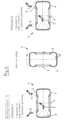
- the tire 1 lies flat on a base.
- the side surface 2 lies on the horizontal base (not shown in the drawing).
- the other side surface 3 is on top and is freely accessible.
- the tire center axis 4 runs vertically.
- the tire 1 is not mounted on a rim.
- the first test head 5 is moved into the interior of the tire 1.
- the test head 5 is vertically movable. It can also be horizontally movable. Furthermore, the test head can be pivoted about a horizontal axis.
- the second test head 6 and the third test head 7 are positioned above the tire in such a way that they can test the upper side surface 3 of the tire 1.
- the test heads 6 and 7 are offset by 180° in the circumferential direction. They are located opposite each other.
- the tire 1 and the test heads 5, 6, 7 can be located in a pressure chamber, in particular a vacuum chamber, of the tire testing device. In the first test run, the tire 1 is rotated by 180° around the vertical axis 4. Instead or in addition, the test heads 5, 6, 7 can be rotated to allow a relative rotation of the tire 1 with respect to the test heads 5, 6, 7. In this way, half of the inner running surface 8 and the entire side surface 3 are tested in the first test run.
- the tire is then turned ("flipped") so that the side surface 2 that was previously on the base is now on top and the tire with the tested side surface 3 rests on the base.
- the test head 5 can be moved out of the tire 1 beforehand.
- the tire 1 can be taken out of the tire testing device for turning and then put back into the tire testing device. This can be done manually or using a turning device.
- a mark can be applied to the tire 1 to ensure that the tire is positioned correctly in the tire testing device after turning.
- the tire testing device can have a position detection device for detecting the position of the tire 1 before and/or after turning the tire 1.
- the tire testing device can have a positioning device for positioning the tire in the correct position after turning the tire.
- the tire is again rotated by 180° and/or the test heads 5, 6, 7 are rotated so that the tire 1 rotates by 180° relative to the test heads 5, 6, 7.
- the angle of rotation can be somewhat larger than 180° in order to create a certain overlap area.
- the marking device and/or position detection device and/or positioning device ensure that both halves of the inner surface, in particular the inner tread, of the tire are tested.
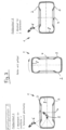
- test heads 5, 9 for the inner surface of the tire and four test heads 6, 7, 10, 11 for the side surface of the tire.
- the test heads 5, 9 and the test heads 6, 7, 10, 11 are each offset by 90° in the circumferential direction.
- a relative rotation of 90° or slightly more than 90° between the tire and the test heads is sufficient to fully test the tire.
- Fig.3 An example with two test heads is shown.
- the first test head is used to test the inner surface, in particular the inner tread 8, of the tire 1.
- the second test head is used to test a side surface of the tire 1.
- the invention makes it possible to reduce the number of test runs from three to two.
- three test heads or an integer multiple of three test heads are used, with two test heads or two thirds of the test heads testing the entire first sidewall from the outside, while the third test head or the third third of the test heads examines half of the inner surface or inner tread. After turning the tire over, the second sidewall and the second half of the inner surface of the tire are tested in the same way in a second test run.
- the tire can be rotated relative to the test heads.
- the test heads can also be rotated separately or together around the circumference of the tire. Both options can also be combined.
Landscapes
- Physics & Mathematics (AREA)
- General Physics & Mathematics (AREA)
- Tires In General (AREA)
Claims (12)
- Installation de vérification de pneus destinée à vérifier des pneus dont la surface latérale (2) est posée à plat sur un soubassement horizontal, avec un appareil de vérification de pneus,
caractérisée en ce que
l'appareil de vérification de pneus présente plusieurs têtes de vérification (5, 9) destinées vérifier la surface intérieure de roulement (8) du pneu (1) et un nombre double de têtes de vérification (6, 10, 7, 11) destinées vérifier la surface latérale extérieure (3, 2) du pneu (1). - Installation de vérification de pneus selon la revendication 1, caractérisée par un dispositif de retournement destiné à retourner le pneu (1).
- Installation de vérification de pneus selon la revendication 2, caractérisée par un dispositif de marquage destiné à marquer le pneu (1) avant le retournement du pneu (1).
- Installation de vérification de pneus selon l'une des revendications 2 ou 3, caractérisée par un dispositif de saisie de position destiné à saisir la position du pneu (1) avant et/ou après le retournement du pneu (1).
- Installation de vérification de pneus selon l'une des revendications 2 à 4, caractérisée par un dispositif de positionnement destiné à positionner correctement le pneu (1) après le retournement du pneu (1).
- Procédé de vérification de pneus comprenant une installation de vérification de pneus selon l'une des revendications précédentes,
caractérisé en ce queune, plusieurs ou toutes les têtes de vérification (5, 9 ; 6, 7, 10, 11) vérifient une partie (8 ; 3, 2) du pneu (1),en ce que le pneu (1) est retourné eten ce qu'une, plusieurs ou toutes les têtes de vérification (5, 9 ; 6, 7, 10, 11) vérifient la partie restante (8 ; 2, 3) du pneu. - Procédé selon la revendication 6, caractérisé en ce que les têtes de vérification (5, 9 ; 6, 7, 10, 11) vérifient la surface intérieure de roulement (8) et la surface latérale extérieure (3, 2) du pneu (1).
- Procédé selon la revendication 6 ou 7, caractérisé en ce qu'avant ou après le retournement du pneu (1), une surface latérale extérieure (3, 2) et une moitié de la surface intérieure de roulement (8) du pneu (1) sont vérifiées et en ce qu'après ou avant le retournement du pneu (1), l'autre surface latérale extérieure (2, 3) et l'autre moitié de la surface intérieure de roulement (8) du pneu (1) sont vérifiées.
- Procédé selon la revendication 6 ou 7, caractérisé en ce qu'avant ou après le retournement du pneu (1), une surface latérale extérieure (3, 2) et la surface intérieure de roulement (8) du pneu (1) sont vérifiées et en ce qu'après ou avant le retournement du pneu (1), l'autre surface latérale extérieure (2, 3) du pneu (1) est vérifiée.
- Procédé selon l'une des revendications 6 à 9, caractérisé en ce que le pneu (1) est marqué avant le retournement.
- Procédé selon l'une des revendications 6 à 10, caractérisé en ce que la position du pneu (1) est saisie avant et/ou après le retournement.
- Procédé selon l'une des revendications 6 à 11, caractérisé en ce que le pneu (1) est positionné correctement après le retournement.
Applications Claiming Priority (2)
| Application Number | Priority Date | Filing Date | Title |
|---|---|---|---|
| DE102007038176A DE102007038176A1 (de) | 2007-08-13 | 2007-08-13 | Reifenprüfanlage |
| EP08012116A EP2026056A3 (fr) | 2007-08-13 | 2008-07-04 | Dispositif d'essai de pneu |
Related Parent Applications (2)
| Application Number | Title | Priority Date | Filing Date |
|---|---|---|---|
| EP08012116.3 Division | 2008-07-04 | ||
| EP08012116A Division EP2026056A3 (fr) | 2007-08-13 | 2008-07-04 | Dispositif d'essai de pneu |
Publications (3)
| Publication Number | Publication Date |
|---|---|
| EP2549258A1 EP2549258A1 (fr) | 2013-01-23 |
| EP2549258B1 EP2549258B1 (fr) | 2018-12-05 |
| EP2549258B2 true EP2549258B2 (fr) | 2024-07-31 |
Family
ID=39971076
Family Applications (2)
| Application Number | Title | Priority Date | Filing Date |
|---|---|---|---|
| EP08012116A Ceased EP2026056A3 (fr) | 2007-08-13 | 2008-07-04 | Dispositif d'essai de pneu |
| EP12007247.5A Active EP2549258B2 (fr) | 2007-08-13 | 2008-07-04 | Dispositif d'essai de pneu |
Family Applications Before (1)
| Application Number | Title | Priority Date | Filing Date |
|---|---|---|---|
| EP08012116A Ceased EP2026056A3 (fr) | 2007-08-13 | 2008-07-04 | Dispositif d'essai de pneu |
Country Status (4)
| Country | Link |
|---|---|
| US (1) | US7810388B2 (fr) |
| EP (2) | EP2026056A3 (fr) |
| JP (1) | JP2009047691A (fr) |
| DE (1) | DE102007038176A1 (fr) |
Families Citing this family (6)
| Publication number | Priority date | Publication date | Assignee | Title |
|---|---|---|---|---|
| DE102006015123B4 (de) * | 2006-03-31 | 2008-03-20 | Mähner, Bernward | Vorrichtung und Verfahren zum Prüfen eines Reifens, insbesondere mittels eines interferometrischen Messverfahrens |
| DE102007038176A1 (de) * | 2007-08-13 | 2009-02-19 | Steinbichler Optotechnik Gmbh | Reifenprüfanlage |
| EP2353890A1 (fr) * | 2010-01-29 | 2011-08-10 | Snap-on Equipment Srl a unico socio | Procédé et appareil pour déterminer les dimensions géométriques d'une roue de véhicule avec des capteurs optiques |
| DE102013010402A1 (de) | 2013-06-21 | 2014-12-24 | Steinbichler Optotechnik Gmbh | Reifenprüfgerät, Reifenprüfanlage und Verfahren zur Reifenprüfung |
| DE102022115800B3 (de) | 2022-04-08 | 2022-11-24 | Stefan Dengler | Verfahren und Vorrichtung zum Prüfen eines Reifens, insbesondere mittels eines interferometrischen Messverfahrens |
| DE102023132675B3 (de) | 2023-11-23 | 2024-12-24 | Stefan Dengler | Vorrichtung und Verfahren zum Prüfen eines Reifens, insbesondere mittels eines interferometrischen Messverfahrens |
Family Cites Families (32)
| Publication number | Priority date | Publication date | Assignee | Title |
|---|---|---|---|---|
| DE2721215C3 (de) * | 1977-05-11 | 1981-02-05 | Opto-Produkte Ag, Zuerich (Schweiz) | Reifenprüfgerät zur zerstörungsfreien holographischen Werkstoffprüfung von Fahr- und Flugzeugreifen auf Fehlstellen |
| US4702594A (en) * | 1982-11-15 | 1987-10-27 | Industrial Holographics, Inc. | Double exposure interferometric analysis of structures and employing ambient pressure stressing |
| JPS63202432A (ja) * | 1987-02-18 | 1988-08-22 | Honda Motor Co Ltd | タイヤ反転装置 |
| US4936138A (en) * | 1988-09-14 | 1990-06-26 | Oliver Rubber Company | Method and apparatus for tire inspection |
| DE4232201A1 (de) * | 1992-09-25 | 1994-03-31 | Sp Reifenwerke Gmbh | Vorrichtung zur Querschnittsvermessung von Fahrzeugreifen |
| US5703680A (en) * | 1996-01-16 | 1997-12-30 | The Goodyear Tire & Rubber Company | Method for dynamic interference pattern testing |
| DE59813129D1 (de) * | 1997-06-10 | 2005-12-01 | Beissbarth Gmbh | Verfahren und Vorrichtung zum Prüfen von Reifen |
| DE19731486C2 (de) * | 1997-07-22 | 2001-02-22 | Beissbarth Gmbh | Reifenprüfvorrichtung |
| JP3949796B2 (ja) * | 1997-11-06 | 2007-07-25 | 株式会社ブリヂストン | タイヤ形状判定装置 |
| EP1043578B1 (fr) * | 1999-04-09 | 2004-10-13 | Steinbichler Optotechnik Gmbh | Appareil optique pour tester des roues |
| US6225576B1 (en) | 1999-04-20 | 2001-05-01 | Cts Corporation | Shear beam load cell |
| JP4265707B2 (ja) * | 1999-06-08 | 2009-05-20 | 株式会社ブリヂストン | タイヤチャック装置およびタイヤチャック方法 |
| US6791695B2 (en) * | 1999-06-16 | 2004-09-14 | Bandag Licensing Corporation | Shearographic imaging machine with archive memory for animation data and air handling system |
| US6417918B1 (en) * | 1999-09-22 | 2002-07-09 | Bridgestone Corporation | Tire Inspecting method and apparatus |
| EP1099947A3 (fr) | 1999-11-12 | 2003-01-29 | Laser Technology Inc. | Procédé et dispositif pour faire un essai optique d'un pneu |
| GB2369607B (en) * | 2000-12-01 | 2003-11-12 | Billy-Jay Smart | Vessel navigation and docking system and method |
| EP1284409A1 (fr) | 2001-08-16 | 2003-02-19 | Bernward Mähner | Procédé et appareil pour l'inspection de la déformation d'objets |
| JP2003240521A (ja) | 2002-02-21 | 2003-08-27 | Bridgestone Corp | 被検体の外観・形状検査方法とその装置、及び、被検体の外観・形状検出装置 |
| DE20205944U1 (de) | 2002-04-16 | 2003-08-21 | Steinbichler Optotechnik GmbH, 83115 Neubeuern | Reifenprüfgerät |
| US6988397B1 (en) * | 2003-02-11 | 2006-01-24 | Akron Special Machinery, Inc. | Rim chucking machine |
| DE10319099B4 (de) * | 2003-04-28 | 2005-09-08 | Steinbichler Optotechnik Gmbh | Verfahren zur Interferenzmessung eines Objektes, insbesondere eines Reifens |
| JP4238071B2 (ja) * | 2003-06-12 | 2009-03-11 | 株式会社ブリヂストン | マーキング装置 |
| DE10333802B4 (de) * | 2003-07-24 | 2005-09-08 | Steinbichler Optotechnik Gmbh | Verfahren und Vorrichtung zum Prüfen von Reifen |
| US6934018B2 (en) * | 2003-09-10 | 2005-08-23 | Shearographics, Llc | Tire inspection apparatus and method |
| DE20314939U1 (de) | 2003-09-30 | 2003-12-11 | Dengler, Stefan | Reifenprüfeinrichtung mit hängendem Reifen |
| US6935170B2 (en) * | 2003-11-05 | 2005-08-30 | Bruce L Saunders | Tire inspection apparatus |
| US8157613B2 (en) * | 2004-02-27 | 2012-04-17 | Akron Special Machinery, Inc. | Tire uniformity machine grinding assembly |
| DE102006001848A1 (de) * | 2006-01-13 | 2007-07-26 | Steinbichler Optotechnik Gmbh | Prüfgerät für Reifen und dergleichen |
| DE102006015123B4 (de) * | 2006-03-31 | 2008-03-20 | Mähner, Bernward | Vorrichtung und Verfahren zum Prüfen eines Reifens, insbesondere mittels eines interferometrischen Messverfahrens |
| DE102006061003B4 (de) * | 2006-12-22 | 2009-03-26 | Mähner, Bernward | Vorrichtung zum Prüfen eines Prüfobjekts, insbesondere eines Reifens, mittels eines zerstörungsfreien Messverfahrens |
| DE102007009040C5 (de) | 2007-02-16 | 2013-05-08 | Bernward Mähner | Vorrichtung und Verfahren zum Prüfen eines Reifens, insbesondere mittels eines interferometrischen Messverfahrens |
| DE102007038176A1 (de) * | 2007-08-13 | 2009-02-19 | Steinbichler Optotechnik Gmbh | Reifenprüfanlage |
-
2007
- 2007-08-13 DE DE102007038176A patent/DE102007038176A1/de not_active Ceased
-
2008
- 2008-07-04 EP EP08012116A patent/EP2026056A3/fr not_active Ceased
- 2008-07-04 EP EP12007247.5A patent/EP2549258B2/fr active Active
- 2008-08-04 JP JP2008201114A patent/JP2009047691A/ja active Pending
- 2008-08-06 US US12/186,943 patent/US7810388B2/en active Active
Also Published As
| Publication number | Publication date |
|---|---|
| JP2009047691A (ja) | 2009-03-05 |
| EP2026056A2 (fr) | 2009-02-18 |
| US7810388B2 (en) | 2010-10-12 |
| DE102007038176A1 (de) | 2009-02-19 |
| EP2026056A3 (fr) | 2010-12-29 |
| US20090044615A1 (en) | 2009-02-19 |
| EP2549258B1 (fr) | 2018-12-05 |
| EP2549258A1 (fr) | 2013-01-23 |
Similar Documents
| Publication | Publication Date | Title |
|---|---|---|
| EP2002235B1 (fr) | Dispositif et procede de controle d'un pneumatique, en particulier au moyen d'une mesure interferometrique | |
| EP1959227B2 (fr) | Dispositif et procédé destinés à la vérification d'un pneu, en particulier à l'aide d'un procédé de mesure interférométrique | |
| DE3137248C2 (fr) | ||
| EP2549258B2 (fr) | Dispositif d'essai de pneu | |
| DE102012007270B4 (de) | Reifenprüfgerät und Verfahren zum Prüfen eines Reifens | |
| EP1999448B1 (fr) | Dispositif et procédé pour vérifier un pneumatique, notamment au moyen d'un procédé de mesure interférométrique | |
| DE102009036145A1 (de) | Biaxiale Rad-Testanordnung | |
| EP3787900A1 (fr) | Procédé de surveillance d'un cylindre d'impression et ensemble correspondant | |
| EP1647817B1 (fr) | Méthode et dispositif pour test optique de surface de roue | |
| EP4416459B1 (fr) | Procédé de test de pneumatiques | |
| EP1999447A1 (fr) | Dispositif et procédé de contrôle d'un pneu | |
| WO2014096452A1 (fr) | Dispositif et procédé destinés à vérifier un pneumatique au moyen d'un procédé de mesure par interférométrie, notamment par shearographie | |
| DE19944314C2 (de) | Prüfgerät für Reifen | |
| EP0884560B1 (fr) | Procédé et dispositif de contrôle des pneus | |
| DE102006053161B4 (de) | Reifenprüfanlage und Verfahren zu ihrem Betrieb | |
| DE102009008468B4 (de) | Verfahren zur Prüfung von Reifen | |
| EP4560259B1 (fr) | Dispositif et procédé de contrôle d'un pneumatique, en particulier au moyen d'un procédé de mesure interférométrique | |
| DE102006001848A1 (de) | Prüfgerät für Reifen und dergleichen | |
| DE69621854T2 (de) | Verfahren zur angepassten erwärmung einer maschine zur erfassung von kraftänderungen | |
| DE102019121662A1 (de) | Verfahren zur Prüfung eines Reifens | |
| DE102021118449B3 (de) | Vorrichtung und Verfahren zur Bildaufnahme eines Reifens eines Fahrzeugs | |
| DE102005032735B3 (de) | Vorrichtung und Verfahren zum Prüfen eines Reifens | |
| DE102019212060A1 (de) | Verfahren zum Ausbessern von Oberflächenanomalien an vulkanisierten Reifen | |
| DE102022126613A1 (de) | Verfahren zum Prüfen von Reifen | |
| EP1225435A2 (fr) | Procédé et dispositif d'essai de pneus |
Legal Events
| Date | Code | Title | Description |
|---|---|---|---|
| PUAI | Public reference made under article 153(3) epc to a published international application that has entered the european phase |
Free format text: ORIGINAL CODE: 0009012 |
|
| AC | Divisional application: reference to earlier application |
Ref document number: 2026056 Country of ref document: EP Kind code of ref document: P |
|
| AK | Designated contracting states |
Kind code of ref document: A1 Designated state(s): AT BE BG CH CY CZ DE DK EE ES FI FR GB GR HR HU IE IS IT LI LT LU LV MC MT NL NO PL PT RO SE SI SK TR |
|
| 17P | Request for examination filed |
Effective date: 20130719 |
|
| RBV | Designated contracting states (corrected) |
Designated state(s): AT BE BG CH CY CZ DE DK EE ES FI FR GB GR HR HU IE IS IT LI LT LU LV MC MT NL NO PL PT RO SE SI SK TR |
|
| STAA | Information on the status of an ep patent application or granted ep patent |
Free format text: STATUS: EXAMINATION IS IN PROGRESS |
|
| 17Q | First examination report despatched |
Effective date: 20171016 |
|
| TPAC | Observations filed by third parties |
Free format text: ORIGINAL CODE: EPIDOSNTIPA |
|
| RAP1 | Party data changed (applicant data changed or rights of an application transferred) |
Owner name: CARL ZEISS OPTOTECHNIK GMBH |
|
| GRAP | Despatch of communication of intention to grant a patent |
Free format text: ORIGINAL CODE: EPIDOSNIGR1 |
|
| STAA | Information on the status of an ep patent application or granted ep patent |
Free format text: STATUS: GRANT OF PATENT IS INTENDED |
|
| INTG | Intention to grant announced |
Effective date: 20180525 |
|
| TPAC | Observations filed by third parties |
Free format text: ORIGINAL CODE: EPIDOSNTIPA |
|
| RBV | Designated contracting states (corrected) |
Designated state(s): DE FR IT |
|
| RIN1 | Information on inventor provided before grant (corrected) |
Inventor name: SUN, JUNLI Inventor name: HUBER, RAINER Inventor name: STEINBICHLER, MARCUS, DR. Inventor name: LEITNER, BERND |
|
| GRAJ | Information related to disapproval of communication of intention to grant by the applicant or resumption of examination proceedings by the epo deleted |
Free format text: ORIGINAL CODE: EPIDOSDIGR1 |
|
| STAA | Information on the status of an ep patent application or granted ep patent |
Free format text: STATUS: EXAMINATION IS IN PROGRESS |
|
| GRAR | Information related to intention to grant a patent recorded |
Free format text: ORIGINAL CODE: EPIDOSNIGR71 |
|
| GRAS | Grant fee paid |
Free format text: ORIGINAL CODE: EPIDOSNIGR3 |
|
| STAA | Information on the status of an ep patent application or granted ep patent |
Free format text: STATUS: GRANT OF PATENT IS INTENDED |
|
| INTC | Intention to grant announced (deleted) | ||
| GRAA | (expected) grant |
Free format text: ORIGINAL CODE: 0009210 |
|
| RIN1 | Information on inventor provided before grant (corrected) |
Inventor name: LEITNER, BERND Inventor name: STEINBICHLER, MARCUS, DR. Inventor name: SUN, JUNLI Inventor name: HUBER, RAINER |
|
| INTG | Intention to grant announced |
Effective date: 20181025 |
|
| GRAA | (expected) grant |
Free format text: ORIGINAL CODE: 0009210 |
|
| STAA | Information on the status of an ep patent application or granted ep patent |
Free format text: STATUS: THE PATENT HAS BEEN GRANTED |
|
| AC | Divisional application: reference to earlier application |
Ref document number: 2026056 Country of ref document: EP Kind code of ref document: P |
|
| AK | Designated contracting states |
Kind code of ref document: B1 Designated state(s): DE FR IT |
|
| REG | Reference to a national code |
Ref country code: DE Ref legal event code: R096 Ref document number: 502008016509 Country of ref document: DE |
|
| REG | Reference to a national code |
Ref country code: DE Ref legal event code: R026 Ref document number: 502008016509 Country of ref document: DE |
|
| PLBI | Opposition filed |
Free format text: ORIGINAL CODE: 0009260 |
|
| PLAX | Notice of opposition and request to file observation + time limit sent |
Free format text: ORIGINAL CODE: EPIDOSNOBS2 |
|
| 26 | Opposition filed |
Opponent name: ISYM INFORMATIONS- UND SYSTEMTECHNIK GMBH Effective date: 20190905 |
|
| PLBB | Reply of patent proprietor to notice(s) of opposition received |
Free format text: ORIGINAL CODE: EPIDOSNOBS3 |
|
| APBM | Appeal reference recorded |
Free format text: ORIGINAL CODE: EPIDOSNREFNO |
|
| APBP | Date of receipt of notice of appeal recorded |
Free format text: ORIGINAL CODE: EPIDOSNNOA2O |
|
| APAH | Appeal reference modified |
Free format text: ORIGINAL CODE: EPIDOSCREFNO |
|
| APBM | Appeal reference recorded |
Free format text: ORIGINAL CODE: EPIDOSNREFNO |
|
| APBP | Date of receipt of notice of appeal recorded |
Free format text: ORIGINAL CODE: EPIDOSNNOA2O |
|
| APBQ | Date of receipt of statement of grounds of appeal recorded |
Free format text: ORIGINAL CODE: EPIDOSNNOA3O |
|
| APBQ | Date of receipt of statement of grounds of appeal recorded |
Free format text: ORIGINAL CODE: EPIDOSNNOA3O |
|
| APBU | Appeal procedure closed |
Free format text: ORIGINAL CODE: EPIDOSNNOA9O |
|
| PUAH | Patent maintained in amended form |
Free format text: ORIGINAL CODE: 0009272 |
|
| STAA | Information on the status of an ep patent application or granted ep patent |
Free format text: STATUS: PATENT MAINTAINED AS AMENDED |
|
| 27A | Patent maintained in amended form |
Effective date: 20240731 |
|
| AK | Designated contracting states |
Kind code of ref document: B2 Designated state(s): DE FR IT |
|
| REG | Reference to a national code |
Ref country code: DE Ref legal event code: R102 Ref document number: 502008016509 Country of ref document: DE |
|
| REG | Reference to a national code |
Ref country code: DE Ref legal event code: R081 Ref document number: 502008016509 Country of ref document: DE Owner name: ITALMATIC SRL, IT Free format text: FORMER OWNER: CARL ZEISS OPTOTECHNIK GMBH, 83115 NEUBEUERN, DE |
|
| PGFP | Annual fee paid to national office [announced via postgrant information from national office to epo] |
Ref country code: DE Payment date: 20250731 Year of fee payment: 18 |
|
| PGFP | Annual fee paid to national office [announced via postgrant information from national office to epo] |
Ref country code: IT Payment date: 20250729 Year of fee payment: 18 |
|
| PGFP | Annual fee paid to national office [announced via postgrant information from national office to epo] |
Ref country code: FR Payment date: 20250729 Year of fee payment: 18 |