EP1959227B2 - Dispositif et procédé destinés à la vérification d'un pneu, en particulier à l'aide d'un procédé de mesure interférométrique - Google Patents
Dispositif et procédé destinés à la vérification d'un pneu, en particulier à l'aide d'un procédé de mesure interférométrique Download PDFInfo
- Publication number
- EP1959227B2 EP1959227B2 EP07150011.0A EP07150011A EP1959227B2 EP 1959227 B2 EP1959227 B2 EP 1959227B2 EP 07150011 A EP07150011 A EP 07150011A EP 1959227 B2 EP1959227 B2 EP 1959227B2
- Authority
- EP
- European Patent Office
- Prior art keywords
- measuring
- tyre
- tire
- test
- heads
- Prior art date
- Legal status (The legal status is an assumption and is not a legal conclusion. Google has not performed a legal analysis and makes no representation as to the accuracy of the status listed.)
- Not-in-force
Links
Images




Classifications
-
- G—PHYSICS
- G01—MEASURING; TESTING
- G01B—MEASURING LENGTH, THICKNESS OR SIMILAR LINEAR DIMENSIONS; MEASURING ANGLES; MEASURING AREAS; MEASURING IRREGULARITIES OF SURFACES OR CONTOURS
- G01B11/00—Measuring arrangements characterised by the use of optical techniques
- G01B11/16—Measuring arrangements characterised by the use of optical techniques for measuring the deformation in a solid, e.g. optical strain gauge
- G01B11/161—Measuring arrangements characterised by the use of optical techniques for measuring the deformation in a solid, e.g. optical strain gauge by interferometric means
-
- G—PHYSICS
- G01—MEASURING; TESTING
- G01B—MEASURING LENGTH, THICKNESS OR SIMILAR LINEAR DIMENSIONS; MEASURING ANGLES; MEASURING AREAS; MEASURING IRREGULARITIES OF SURFACES OR CONTOURS
- G01B11/00—Measuring arrangements characterised by the use of optical techniques
- G01B11/24—Measuring arrangements characterised by the use of optical techniques for measuring contours or curvatures
- G01B11/2441—Measuring arrangements characterised by the use of optical techniques for measuring contours or curvatures using interferometry
-
- G—PHYSICS
- G01—MEASURING; TESTING
- G01M—TESTING STATIC OR DYNAMIC BALANCE OF MACHINES OR STRUCTURES; TESTING OF STRUCTURES OR APPARATUS, NOT OTHERWISE PROVIDED FOR
- G01M17/00—Testing of vehicles
- G01M17/007—Wheeled or endless-tracked vehicles
- G01M17/02—Tyres
- G01M17/027—Tyres using light, e.g. infrared, ultraviolet or holographic techniques
Definitions
- the present invention relates to a device and a method for testing a tire, in particular by means of an interferometric measuring method.
- the object to be tested is a tire, but other components can also be tested using the device according to the invention.
- the measuring method used to test the tire is in particular an interferometric measuring method.
- the device has a measuring device by which the tire can be scanned to generate a measurement result.
- the device is also provided with a positioning means by which the measuring device can be positioned in a measuring position and aligned in a measuring direction.
- Tires or other components that are subjected to stress during use are subjected to a material test for quality control and to reduce safety risks. This allows faulty areas, known as defects, to be identified. In particular, when it comes to used tires that are to be retreaded, non-destructive material testing is usually used, which ensures a comparatively quick series of tests.
- Optical measuring methods are often used in industrial practice, such as holography or shearography, also known as speckle pattern shearing interferometry.
- Shearography is a relative interferometric measuring method that produces a result image that shows the difference between two temporally offset states of the test object.
- the result image which is nowadays usually digital due to the increasing use of electronic image sensors such as CCD or CMOS sensors, it is therefore necessary to change the state of the test object between two measurements by applying a mechanical, thermal or pneumatic force.
- known devices have a pressure chamber that is either evacuated or pressurized, so that the test object in the pressure chamber is deformed as a result of the pressure change and thus changes from a first reference state to a second measurement state.
- shearography does not determine the deformation on the surface of a test object, but measures the gradient of the deformation. This is due to the fact that shearography uses a so-called shearing element, which is a shear optic, such as an optical wedge, an optical biprism or a Michelson interferometer, which creates an image doubling.
- the shearing element creates two slightly spatially offset images of the test object, which are superimposed to generate an interferogram based on the interference that results in this way.
- the shearogram characterizing the gradient of the deformation is generated by subtracting the intensities of the interferograms obtained in the reference state and the measurement state.
- the shearogram shows whether the position of a point in relation to a neighboring point has changed due to the deformation of the test object. If so, then this path difference leads to a local change in the intensity distribution. which provides information about a defect.
- Interferometric measurement methods based on this speckle interferometry are used in DE 42 31 578 A1 and EP 1 014 036 B1 described.
- the devices used to test a test object using an interferometric measuring method are usually provided with at least one measuring head, which has an illumination unit and an image recording unit.
- the illumination unit is often formed by a laser or laser diodes that emit coherent light.
- the image recording unit is usually a camera that is provided with an image sensor, i.e. a light-sensitive semiconductor sensor, for example a CCD or CMOS sensor. In order to obtain a meaningful measurement result, it is necessary to coordinate the field of view of the camera and the section of the test object to be tested.
- Such coordination is usually carried out by positioning the measuring head in a measuring position and aligning it in a measuring direction that ensures that, on the one hand, the selected measuring section of the test object is completely captured by the angle of view of the camera and thus lies in the field of view of the camera, and, on the other hand, successive measuring sections overlap sufficiently to enable a gapless test.
- the measuring position and the measuring direction of the measuring head depend on the dimensions of the test object. Consequently, the EP 1 284 409 A1 A device is known which makes it possible to measure the test object optically, for example by means of so-called light sections, in order to position and align the measuring head depending on the data obtained in this way.
- a tire testing device in which a tire to be tested without rim and wheel disc is placed in a lying position in a pressure chamber discloses the EP 1 043 578 B1
- the tire testing device has several measuring heads that are located at a predetermined distance from the inner surface of the tire to inspect the tire's substructure, i.e. the carcass, a belt often located between the carcass and the tread, and the tire's sidewall from the inside.
- the measuring heads each have a lighting unit and an image recording unit and are arranged at an angle to each other so that different sections of the tire can be inspected simultaneously in order to achieve a comparatively fast inspection.
- the measuring heads are connected to a positioning device that allows the measuring heads to be moved from a parking position outside the tire, which allows the tires to be tested to be changed, to a measuring position inside the tire.
- the positioning device has an arm that can be adjusted in the axial direction of the tire and on which the measuring heads are arranged.
- the measuring heads are adjustable in the radial direction of the tire and are arranged on the arm so that they can rotate about a pivot axis.
- the known tire testing device has the disadvantage that, due to the arrangement of the measuring heads in the measuring position inside the tire, only tires with a comparatively large inner diameter can be tested.
- the arrangement of the measuring heads that can rotate around a pivot axis which is absolutely necessary in order to be able to fully test the inner surface of the tire, has proven to be disadvantageous. This is because the pivoting arrangement of the measuring heads requires a high level of mechanical and control technology effort, which is accompanied by cost-intensive production.
- a method and apparatus for measuring the shape and/or deformation of an object which may be a tire, is described in EP 1 473 539 A1 described.
- a first image is taken with a first setting that is adapted to a first image area and a second image with a second setting that is adapted to a second image area using a camera. Both images are then combined.
- EP 1 099 947 A2 a method and a device for carrying out an optical tire inspection are known.
- the key areas of a tire to be tested in particular the tread section, the shoulders and the beads on both sidewalls, are inspected in two test runs using two height-adjustable cameras along the entire circumference.
- an upper camera inspects the upper shoulder/sidewall area from the outside and a lower camera inspects the inner shoulder area up to the tread section.
- the measuring position of the cameras is then changed and in a second test run the upper camera inspects the inner lower shoulder and the lower camera inspects the lower bead area.
- four cameras arranged 90° apart with a viewing angle of 45° each can be provided.
- EP 1 808 686 A1 a test device for hollow test objects, such as tires, pipes or tanks, is known.
- the test device comprises a closure which serves to close an opening of the test object.
- the test object further comprises a test arrangement which is located inside the test object in order to test the test object.
- the closure is connected to a pressure feedthrough in an airtight manner.
- the pressure feedthrough serves to generate a negative pressure or an overpressure in the cavity formed by the closure. Pressurizing a tire from the inside makes the provision of a vacuum chamber unnecessary.
- the invention is based on the object of creating a device and a test arrangement for testing a tire, which enable a quick and complete test of the tire.
- the device according to the invention for testing a tire has a measuring device by which the tire can be scanned to generate a measurement result.
- the measuring device has at least three measuring heads, which can, for example, have a design as shown in the EP 1 014 036 B1 is described in order to test the tire using an interferometric measuring method.
- the measuring heads it is also possible for the measuring heads to have a design that enables other non-destructive measuring methods to be carried out, such as ultrasonic testing or radiographic testing using X-rays.
- the device according to the invention is further provided with a positioning means by which the measuring heads can be positioned in their respective measuring position and aligned in their respective measuring direction.
- the positioning means is designed so that at least two of the measuring heads of the measuring device can be aligned in measuring directions that enable the outer surface of the side walls to be scanned.
- the positioning means is also designed such that at least one of the measuring heads of the measuring device can be aligned in a measuring direction which makes it possible to scan the inner surface of the tire, at least in the region of the tread section.
- the test device has at least three measuring heads.
- the first measuring head and the second measuring head are positioned and aligned so that the outer surface of the side walls can be scanned.
- the third measuring head is positioned and aligned so that the inner surface of at least the tread section can be scanned.
- the tire is intermittently rotated about the axis of rotation relative to the measuring heads and scanned section by section by the measuring heads.
- the first measuring head scans half of the measuring sections on the outer surface of the first side wall
- the second measuring head scans the other half of the measuring sections on the outer surface of the first side wall.
- the third measuring head scans half of the measuring sections on the inner surface.
- the tire After the first test run, the tire is turned over and then, in a second test run, it is again intermittently rotated about the axis of rotation relative to the measuring heads and scanned section by section by the measuring heads.
- the first measuring head then scans one half of the measuring sections on the outer surface of the second side wall, whereas the second measuring head scans the other half of the measuring sections on the outer surface of the second side wall.
- the third measuring head scans the remaining half of the measuring sections on the inner surface.
- the outer surface of both the first sidewall and the second sidewall as well as the inner surface of at least the tread section are completely scanned and the tire is thus completely tested.
- the invention makes use of the knowledge that a complete test of the tire, i.e. a so-called bead-to-bead test, can be achieved by testing the sidewalls from the outside and the tread section from the inside. The sidewalls are scanned using two measuring heads, whereas a single measuring head is sufficient for scanning the tread section.
- the invention is of particular importance when the tire is in a lying position. Position is tested and it is therefore essential to turn the tire in order to be able to test the sidewall, which is located underneath during the first test run, from the outside in the second test run.
- the division of the test of the tread section into the two test runs is particularly important. This division means that the tread section can be completely tested with just one single measuring head during the time period during which the two measuring heads are testing the sidewalls from the outside.
- the device according to the invention can therefore also be used to test tires with a comparatively small inner diameter.
- the device according to the invention can also be equipped with more than three measuring heads if required.
- OTR off-the-road
- the advantage of using the two test runs resulting from turning the tire in order to distribute the testing of the tread section between the two test runs always arises when the arrangement of the measuring heads which test the sidewalls from the outside and the arrangement of the measuring heads which test the tread section from the inside are selected such that the outer surface of the sidewalls is completely tested and the inner surface of the tread section is half tested during one test run.
- the measuring device in a preferred embodiment of the device according to the invention comprises a fourth measuring head which is aligned in a fourth measuring direction to scan the inner surface of at least the tread section.
- the fourth measuring direction and the third measuring direction in which the third measuring head is aligned preferably run in a radial direction of the tire and are preferably oriented in opposite directions for the aforementioned purpose.
- the third and fourth measuring directions it is also possible for the third and fourth measuring directions to extend at an angle to the tire center plane, which corresponds to the tire's plane of symmetry if the tire is symmetrical.
- the first measuring direction and the second measuring direction preferably run in an axial direction of the tire. Depending on the application, however, it is also possible for the first and second measuring directions to run at an angle to an axial plane extending in the axial direction.
- the axial direction is vertical, whereas the radial direction is horizontal.
- At least one of the measuring heads is arranged rigidly with respect to the measuring direction.
- all measuring heads are arranged rigidly in relation to their respective measuring direction.
- the rigid arrangement of the measuring heads i.e. the lack of possibility to rotate the measuring heads in the measuring position about a pivot axis running orthogonally to the measuring direction, offers the advantage of a simple and therefore cost-effective design.
- the rigid arrangement of the measuring heads also offers the advantage of a low-wear and low-maintenance design.
- At least one of the measuring heads can be rotated about a pivot axis running orthogonally to the measuring direction.
- a pivot axis running orthogonally to the measuring direction.
- the measuring head can be pivoted between a first measuring position and a second measuring position.
- the measuring head can advantageously be pivoted from the first measuring position to the second measuring position against the effect of a restoring force caused, for example, by a spring element.
- the movement from the first measuring position to the second measuring position can be generated, for example, by a pneumatically operated actuator.
- the measuring head is aligned in the first measuring position in a measuring direction extending substantially in the axial direction of the tire and in the second measuring position in a measuring direction extending substantially in the radial direction of the tire.
- the measuring head In the first measuring position, the measuring head can be used to measure the side walls of the tire from the outside.
- the measuring head In the second measuring position, the measuring head can be used to check the tread section of the tire from the inside. If the pivoting measuring head is the first measuring head or the second measuring head, then in the second measuring position it can scan the tread section together with the third measuring head in a comparatively short test time if a complete test of the tire is not required.
- the pivoting arrangement of only one of the measuring heads thus ensures that the device according to the invention can be used universally.
- the measuring head can be pivoted in such a way that in the first measuring position it is aligned in a measuring direction extending in the radial direction of the tire and in the second measuring position it is aligned in a measuring direction inclined by an adjustment angle relative to this radial measuring direction.
- Such an embodiment is particularly suitable when the tires to be tested have a comparatively large width and, as a result, the tread section is not completely covered by the viewing angle of the measuring head. Due to the rotation of the measuring head by the adjustment angle, it is possible to carry out a so-called split crown shot, i.e.
- the adjustment angle is between 0° and ⁇ 30°, preferably between 0° and ⁇ 15°. If the inner surface of the tire is tested using a split crown shot, the advantages of the method according to the invention can be achieved if the inner surface of the tire is scanned simultaneously by two measuring heads.
- the device according to the invention has a pressure chamber in which the tire to be tested can be exposed to a predetermined pressure.
- the pressure chamber enables an interferometric, in particular shearographic, measuring method to be carried out in a practical manner.
- the device according to the invention also has a base frame on which the tire can be stored during the test.
- the base frame can also be used to minimize vibrations that occur, such as airborne or structure-borne noise, which could distort the measurement result. It is expedient for not only the positioning device but also the pressure chamber to be supported on the base frame.
- the measuring heads can be moved in the axial direction and in the radial direction by the positioning means.
- the positioning means according to the invention has at least one axial adjustment unit, by means of which the measuring head can be moved in the axial direction, and at least one radial adjustment unit, by means of which the measuring head can be moved in the radial direction.
- Each of the measuring heads is expediently assigned an axial adjustment unit and a radial adjustment unit, so that the measuring heads can be positioned independently of one another in their respective measuring position and aligned in their respective measuring direction.
- the adjustment units are designed, for example, as a linear guide or linear motor and can be coupled to one another. A simple and cost-effective design is obtained if at least two radial adjustment units and/or at least two axial adjustment units are each coupled to one another in such a way that they are driven by a common drive.
- the measuring device is rotatable relative to the tire about a rotation axis or rolling axis extending in the axial direction of the tire in order to completely scan the tire in the circumferential direction.
- the base frame with a rotating device by means of which the tire can be rotated about the rotation axis.
- the relative movement of the tire and the measuring device can be achieved by a rotatable design of the positioning means. The latter design, however, is associated with a high technical effort and enormous space requirements.
- the measuring heads advantageously each comprise a lighting unit by which the tire to be tested is illuminated, a shearing element by which the light beams scattered back by the tire are caused to interfere, and an electronic image sensor which is arranged in the beam path of the shearing element and records the interfering light beams.
- the lighting unit formed for example by laser diodes, can either be an integral part of the measuring heads or be formed separately from them.
- the device according to the invention has a control and evaluation device by means of which the measuring device and/or the positioning means and/or the rotating device and/or the pressure prevailing in the pressure chamber can be controlled and the measurement result obtained can be evaluated.
- the control and evaluation device has an image capture circuit, i.e. a so-called frame or video grabber, by means of which the images recorded by the image sensor of the measuring heads are read in.
- the image capture circuit is expediently multi-channel. designed to be able to read in the images from the measuring heads simultaneously.
- a particularly cost-effective design is achieved when the measuring device has three measuring heads and a three-channel frame grabber is therefore required for the simultaneous reading of the images.
- three-channel frame grabbers are used for processing video signals from conventional color cameras and are therefore inexpensive to purchase on the market.
- the side walls and the tread section are each divided into an even number of measuring sections.
- a division into eight measuring sections has proven to be suitable for most tire types.
- the first test run is carried out on a first test device and the second test run on a second test device.
- the measuring sections are scanned simultaneously by the measuring heads, wherein the tire is expediently placed in a pressure chamber and exposed to a predetermined pressure, so that the measuring heads can interferometrically detect a deformation of the tire resulting from a change in the pressure in the pressure chamber.
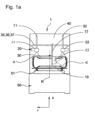
- the in Fig. 1a The device 1 shown is used to test a tire 10 by means of an interferometric measuring method.
- the testing device 1 has a measuring device 20 by which the tire 10 can be scanned to generate a measurement result.
- the measuring device 20 comprises three measuring heads 21, 22, 23, each of which has a design, as they come from the EP 1 014 036 B1 is known to test the tire 10 by means of an interferometric, in particular shearographic, measuring method.
- the measuring heads 21, 22, 23 each have an illumination unit by which the tire 10 can be illuminated and which is formed, for example, by a plurality of laser diodes.
- the measuring heads 21, 22, 23 also each have a shearing element by which the light beams scattered by the tire 10 are caused to interfere.
- the shearing element is composed, for example, of a beam splitter, a movable mirror and a stationary mirror. Furthermore, the measuring heads 21, 22, 23 each have a camera which is provided with an electronic image sensor, for example a CCD or CMOS sensor. The image sensor is arranged in the beam path of the shearing element and serves to record the interfering light beams.
- the testing device 1 has a positioning means 30 by means of which the measuring heads 21, 22, 23 can each be positioned in a measuring position and aligned in a measuring direction.
- the positioning means 30 comprises axial adjustment units 31, 32, 33 by means of which the measuring heads 21, 22, 23 can each be moved in an axial direction z of the tire 10.
- the positioning means 30 comprises radial adjustment units 35, 36, 37 by means of which the measuring heads 21, 22, 23 can each be moved in a radial direction r of the tire 10, which extends orthogonally to the axial direction z.
- Both the axial adjustment units 31, 32, 33 and the radial adjustment units 35, 36, 37 are designed, for example, as a linear guide or linear motor and therefore enable a linear movement of the measuring heads 21, 22, 23 in the axial direction z and the radial direction r.
- One axial adjustment unit 31, 32, 33 and one radial adjustment unit 35, 36, 37 are assigned to a measuring head 21, 22, 23 and are coupled to one another.
- the adjustment units 31, 35 assigned to the measuring head 21 are coupled to one another in such a way that the adjustment unit 31 can be moved in the radial direction r by the adjustment unit 35.
- adjustment units 31, 32, 33, 35, 36, 37 assigned to different measuring heads 21, 22, 23 can also be coupled to one another, in particular to reduce the number of drives and thus ensure a cost-effective design.
- the axial adjustment units 31, 32 can be coupled to one another in order to be moved in the axial direction z by a common drive.
- the test device 1 also has a pressure chamber 40 in which the tire 10 can be subjected to a predetermined pressure.
- the pressure prevailing in the pressure chamber 40 can be an overpressure or a negative pressure.
- a safety valve (not shown) prevents an excessive overpressure or negative pressure from occurring in the pressure chamber 40, which could cause deformation or damage to the pressure chamber 40.
- the device also has a base frame 50 on which the tire 10 is stored during the test and on which the positioning means 30 is supported.
- the tire 10 is, as in Fig. 1a can be seen, is stored lying down. Accordingly, the axial direction z is vertical and the radial direction r is horizontal.
- the base frame 50 is provided with a rotating device 51 which enables rotation of the tire 10 about a rotation axis R.
- the rotation axis R extends in the axial direction z.
- a tire 10 usually has two side walls 11, 13 and a Tread section 15.
- the transition areas from the tread section 15 to the sidewalls 11, 13 are generally referred to as shoulder section or shoulder 16.
- the free, often thickened end of the sidewalls 11, 13 ensures a firm connection between the tire 10 and the rim of a wheel and is usually referred to as bead section or bead 17.
- the supporting substructure of the tire 10 is the carcass 18, which generally consists of one or more layers of a fabric comprising synthetic fibers or steel cords embedded in rubber.
- the carcass 18 is the crucial strength member of the tire 10 and is completed by the belt 19 located in the tread section 15.
- the measuring heads 21, 22, 23 are first positioned in their respective measuring positions and aligned in their respective measuring directions using the adjustment units 31, 32, 33, 35, 36, 37.
- the measuring heads 21, 22 are aligned in a measuring direction extending in the axial direction z to scan the outer surface 12 of the side wall 11 located on top during a first test run and are positioned in a measuring position in which the respective viewing angle ⁇ of the measuring heads 21, 22 completely covers one of the eight measuring sections or sectors in the present case into which the outer surface 12 is divided.
- the measuring head 23 is aligned to scan the inner surface 14 of the tread section 15 in a measuring direction extending in the radial direction r and is positioned in a measuring position in which the viewing angle ⁇ of the measuring head 23 completely covers one of the measuring sections, in this case also eight, into which the inner surface 14 is divided.
- the measuring sections on the outer surface 12 and the inner surface 14 are then illuminated by means of the respective lighting unit of the measuring heads 21, 22, 23.
- the light beams scattered back from the surface of the tire 10 are recorded by means of a lens which the measuring heads 21, 22, 23 each have and imaged onto the respective shearing element of the measuring heads 21, 22, 23 and caused to interfere with it.
- the interfering light beams are recorded by the image sensor of the respective camera of the measuring heads 21, 22, 23 arranged in the beam path of the shearing element in order to generate an interferogram.
- the measuring heads 21, 22, 23 are connected to a control and evaluation device (not shown) which has a multi-channel image capture circuit in order to simultaneously read in the images recorded by the respective image sensor of the measuring heads 21, 22, 23, i.e. interferograms.
- the interferograms are processed in the control and evaluation device in order to create a shearogram indicating the deformation on the surface of the tire 10, for example from different states of the tire 10 which result due to a change in the pressure in the pressure chamber 40.
- the control and evaluation device also serves to control the positioning means 30, the rotating device 51 and the pressure prevailing in the pressure chamber 40.
- Fig. 1c As can be clearly seen, during a first test run all measuring sections on the outer surface 12 of the upper side wall 11 and half of the measuring sections on the inner surface 14 of the tread section 15 are tested. On the outer surface 12 the measuring sections 1a to 4a are scanned one after the other by the measuring head 22 and the measuring sections 5a to 8a are scanned one after the other by the measuring head 21, whereas on the inner surface 14 the measuring sections 1 to 4 are scanned one after the other by the measuring head 23. In order to scan the approximately 45° measuring sections one after the other, the tire 10 is rotated intermittently about the rotation axis R. After the first test run the outer surface 12 of the side wall 11 has been completely tested and the inner surface 14 of the tread section 15 has been half tested.
- the tire 10 is then turned over.
- the outer surface 12 of the then upper side wall 13 is measured by the measuring heads 21, 22 and the inner surface 14 of the tread section 15 is scanned by the measuring head 23.
- the measuring sections 1b to 4b are checked one after the other by the measuring head 21 and the measuring sections 5b to 8b are checked one after the other by the measuring head 22.
- the measuring head 23, checks the measuring sections 5 to 8 on the inner surface 14 one after the other, which were not scanned during the first test run.
- the tire 10 is completely tested, i.e. bead to bead.
- the in Fig. 2a The test arrangement shown has two test devices 1a, 1b, which have the same structure as the previously described test device 1 and which are arranged one behind the other in a test sequence P.
- a turning device 2 is arranged between the test devices 1a, 1b, which makes it possible to rotate the tire 10 about a turning axis W, which in the present case extends in the horizontal direction, in order to turn the tire 10.
- Fig. 2b As can be seen, the previously described first test run is carried out on the first test device 1a in the test sequence P, whereas the second test run is carried out on the second test device 1b in the test sequence P.
- the measuring heads 21, 22, 23 of the testing device 1a test the measuring sections 1a to 8a on the outer surface 12 of the sidewall 11 and the measuring sections 1 to 4 on the inner surface 14 of the tread section 15.
- the measuring heads 21, 22, 23 of the testing device 1b test the measuring sections 1b to 8b on the outer surface 12 of the sidewall 13 and the measuring sections 5 to 8 on the inner surface 14 of the tread section 15 after the tire 10 has been turned by the turning device 2.
- the division of the two test runs between the testing devices 1a, 1b enables an extremely fast series examination of tires 10.
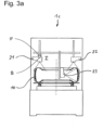
- the test device 1c shown differs from the test device 1 in that the measuring head 21 is pivoted about a pivot axis S is rotatably mounted.
- the measuring heads 22, 23 of the test device 1c are, like all measuring heads 21, 22, 23 of the test device 1, rigidly arranged in relation to the respective measuring direction. Due to the rotatable mounting, the measuring head 21 can be pivoted by an adjustment angle ⁇ , which in the present case is approximately 90°. In this way, it is possible to move the measuring head 21 between a first measuring position I, which is in Fig. 3a shown, and a second measuring position II, which is shown in Fig. 3b shown.
- the measuring head 21 In the first measuring position I, the measuring head 21 is aligned in the axial direction z and thus enables the outer surface 12 of the side walls 11, 13 to be checked. In the second measuring position II, however, the measuring head 21 is aligned in the radial direction r and thus enables the inner surface 14 of the tread section 15 to be checked.
- the pivoting arrangement of the measuring head 21 is particularly useful when the tire 10 is not to be checked completely, but only in the area of the tread section 15. In this case, as in Fig. 3b shown, the measuring heads 21, 23 are arranged together inside the tire 10 and aligned diametrically in order to simultaneously scan the tread portion 15 in a single test run.
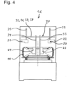
- the test device 1d shown differs from the test device 1 primarily in that the measuring device 20 has a fourth measuring head 24.
- the positioning means 30 additionally has an axial adjustment unit 34 and a radial adjustment unit 38 in order to position the measuring head 24 in the desired measuring position.
- the measuring head 24 has the same structure as the measuring heads 21, 22, 23 and is aligned diametrically to the measuring head 23 in the radial direction r. In this way, the inner surface 14 of the running surface section 15 can be scanned simultaneously by the measuring heads 23, 24 in order to achieve a particularly fast test.
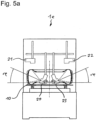
- the test device 1e shown differs from the test device 1d in that the measuring heads 23, 24 are pivotally mounted and can thus be rotated by the adjustment angle ⁇ .
- the adjustment angle ⁇ in this case is approx. +/- 25° in relation to the Fig. 1b shown tire center plane E or a plane parallel to the tire center plane E.
- the measuring heads 23, 24 are each pivoted upwards and thus enable a split crown shot on the tread section 15 including the upper shoulder 16.
- Fig. 5a the measuring heads 23, 24 are each pivoted upwards and thus enable a split crown shot on the tread section 15 including the upper shoulder 16.
- the measuring head 23 is pivoted upwards, while the measuring head 24 is pivoted downwards, so that the measuring head 23 performs a split crown shot on the tread section 15 including the upper shoulder 16 and the measuring head 24 performs a split crown shot on the tread section 15 including the lower shoulder 16.
- the pivoting arrangement of the measuring heads 23, 24 is particularly suitable when the tire 10 to be tested has a comparatively large width and/or a small rim width, so that the tread section 15 would not be completely captured by the viewing angle ⁇ of the measuring heads 23, 24 if the measuring heads 23, 24 were aligned in the radial direction r.
- test devices 1, 1a, 1b, 1c have only three measuring heads 21, 22, 23 and thus have an optimal design to fully test the tire 10 when carrying out the method according to the invention.
- the test devices 1d, 1e which have four measuring heads 21, 22, 23, 24, also make it possible to carry out the method according to the invention, but due to the fourth measuring head 24, not only create redundancy that contributes to a high level of reliability, but also enable the most varied of process controls to be implemented if required.
- the rigid arrangement of most of the measuring heads 21, 22, 23, 24 of the test devices 1, 1a, 1b, 1c, 1d, 1e contributes to a simple and cost-effective design that leads to which is low in wear and maintenance.
Landscapes
- Physics & Mathematics (AREA)
- General Physics & Mathematics (AREA)
- Tires In General (AREA)
- Length Measuring Devices By Optical Means (AREA)
- Length Measuring Devices With Unspecified Measuring Means (AREA)
- Investigating Materials By The Use Of Optical Means Adapted For Particular Applications (AREA)
Claims (20)
- Appareil pour contrôler un pneumatique (10) qui comprend une première paroi latérale (11), une seconde paroi latérale (13) et un tronçon formant bande de roulement (15), qui peuvent être organisés en un certain nombre de tronçons de mesure (1 à 8; 1a à 8a ; 1b à 8b), en particulier au moyen d'un procédé de mesure interférométrique, comprenant:un dispositif de mesure (20) au moyen duquel le pneumatique (10) peut être palpé par tronçons dans une passe de contrôle afin d'engendrer un résultat de mesure ;un châssis (50) sur lequel le pneumatique (10) peut être posé couché de telle façon que la première paroi latérale (11) se trouve en haut dans une première passe de contrôle et, après retournement du pneumatique (10), la seconde paroi latérale (13) se trouve en haut dans une seconde passe de contrôle ;un moyen de positionnement (30) pour le dispositif de mesure (20), qui est supporté sur le châssis (50), etune chambre à pression (40) dans laquelle le pneumatique (10) peut être soumis à une pression prédéterminée ;dans lequel le pneumatique (10) peut être mis en rotation de façon intermittente par rapport au dispositif de mesure (20) autour d'un axe de rotation (R) qui s'étend en direction axiale (z) du pneumatique (10) ;dans lequel le dispositif de mesure (20) comprend :au moins une première tête de mesure (21) qui peut être orientée dans une première direction de mesure (z) pour palper la surface extérieure (12) des parois latérales (11, 13) ;au moins une seconde tête de mesure (22) qui peut être orientée dans une seconde direction de mesure (z) pour palper la surface extérieure (12) des parois latérales (11, 13), etau moins une troisième tête de mesure (23) qui peut être orientée dans une troisième direction de mesure (r) pour palper la surface intérieure (14) au moins du tronçon formant bande de roulement (15) ;dans lequel les moyens de positionnement (30) comprennent au moins une unité de déplacement axial (31, 32, 33) au moyen de laquelle la tête de mesure (21, 22, 23) est déplaçable dans la direction axiale (z), et au moins une unité de déplacement radial (35, 36, 37) au moyen de laquelle la tête de mesure (21, 22, 23) est déplaçable dans la direction radiale (r) ;dans lequel la première tête de mesure (21) et la seconde tête de mesure (22) pouvant être déplacées par le moyen de positionnement (30) dans la direction axiale (z) et dans la direction radiale (r) et pouvant être positionnées chacune dans une position de mesure de telle sorte que dans la première passe de contrôle la totalité des tronçons de mesure (1a à 8a) sur la surface extérieure (12) de la première paroi latérale (11) peuvent être palpés et, dans la seconde passe de contrôle la totalité des tronçons de mesure (1b à 8b) sur la surface extérieure (12) de la seconde paroi latérale (13) peuvent être palpés, etdans lequel la troisième tête de mesure (23) pouvant être déplacée dans la direction axiale (z) et dans la direction radiale (r) et pouvant être positionnée dans une position de mesure par le moyen de positionnement (30) de telle façon que dans la première passe de contrôle une moitié des tronçons de mesure (1 à 4) sur la surface intérieure (14) au moins du tronçon formant bande de roulement (15) peuvent être palpés et, dans la seconde passe de contrôle l'autre moitié des tronçons de mesure (5 à 8) sur la surface intérieure (14) au moins du tronçon formant bande de roulement (15) peuvent être palpés.
- Appareil selon la revendication 1, caractérisé en ce que le dispositif de mesure (20) comprend une quatrième tête de mesure (24) qui peut être orientée dans une quatrième direction de mesure (r) pour palper la surface intérieure (14) au moins du tronçon formant bande de roulement (15).
- Appareil selon la revendication 1 ou 2, caractérisé en ce que la première direction de mesure et la seconde direction de mesure s'étendent dans la direction axiale (z) du pneumatique (10).
- Appareil selon l'une des revendications 1 à 3, caractérisé en ce que la troisième direction de mesure et/ou la quatrième direction de mesure s'étendent dans une direction radiale (r) du pneumatique (10) et sont de préférence orientées en sens opposé.
- Appareil selon l'une des revendications 1 à 4, caractérisé en ce qu'au moins une des têtes de mesure (21, 22, 23, 24), de préférence toutes les têtes de mesure (21, 22, 23, 24), sont agencées de manière rigide par rapport à la direction de mesure (r, z).
- Appareil selon l'une des revendications 1 à 4, caractérisé en ce qu'au moins une des têtes de mesure (21, 22, 23, 24), de préférence toutes les têtes de mesure (21, 22, 23, 24) sont capables de tourner autour d'un axe de pivotement (S) qui s'étend perpendiculairement à la direction de mesure (r, z).
- Appareil selon la revendication 6, caractérisé en ce qu'uniquement une des têtes de mesure (21, 22, 23, 24) est capable de tourner autour de l'axe de pivotement (S).
- Appareil selon la revendication 6 ou 7, caractérisé en ce que la tête de mesure (21, 22, 23, 24) est capable de pivoter entre une première position de mesure (I) et une seconde position de mesure (II), et de préférence la tête de mesure (21, 22, 23, 24) est capable de pivoter à l'encontre de l'action d'une force de rappel de la première position de mesure (I) vers la seconde position de mesure (II).
- Appareil selon la revendication 8, caractérisé en ce que la tête de mesure (21, 22, 23, 24) est orientée dans une direction de mesure axiale (z) dans la première position de mesure (I), et est orientée dans une direction de mesure radiale (r) dans la seconde position de mesure (II).
- Appareil selon la revendication 8, caractérisé en ce que la tête de mesure (21, 22, 23, 24) est orientée dans une direction de mesure radiale (r) dans la première position de mesure (I) et est orientée dans une direction de mesure inclinée à raison d'un angle de décalage (ϕ) par rapport à la direction de mesure radiale (r) dans la seconde position de mesure (II).
- Appareil selon la revendication 10, caractérisé en ce que l'angle de décalage (ϕ) est entre 0° et +/-30°, de préférence entre 0° et +/-15°.
- Appareil selon la revendication 1 à 11, caractérisé en ce que la chambre à pression (40) est soutenus sur le châssis (50).
- Appareil selon l'une des revendications 1 à 12, caractérisé par au moins deux unités de déplacement axial (31, 32, 33, 34) et/ou au moins deux unités de déplacement radial (35, 36, 37, 38) qui sont couplées les unes avec les autres.
- Appareil selon l'une des revendications 1 à 13, caractérisé en ce que le dispositif de mesure (20) est capable de rotation par rapport au pneumatique (10) autour d'un axe de rotation (R) qui s'étend dans la direction axiale (z).
- Appareil selon l'une des revendications 1 à 14, caractérisé en ce que le châssis (50) est pourvu d'un dispositif de rotation (51) au moyen duquel le pneumatique (10) peut être tourné autour de l'axe de rotation (R).
- Appareil selon l'une des revendications 1 à 15, caractérisé en ce que les têtes de mesure (21, 22, 23, 24) comprennent chacune :une unité d'éclairage qui est appropriée pour éclairer le pneumatique (10) ;un élément de Shearing qui est approprié pour amener le faisceau lumineux renvoyé par le pneumatique (10) en interférence, etun capteur d'images électronique qui est agencé dans le trajet des rayons de l'élément de Shearing et qui est approprié pour recevoir le faisceau lumineux en interférence.
- Appareil selon l'une des revendications 1 à 16, caractérisé par une unité de commande et d'évaluation pour commander le dispositif de mesure (20) et/ou les moyens de positionnement (30) et/ou le dispositif de rotation (51) et/ou la pression régnant dans la chambre à pression, et pour évaluer le résultat de mesure.
- Appareil selon la revendication 17, caractérisé en ce que l'unité de commande et d'évaluation comprend un circuit de capture d'images au moyen duquel les images prises par le capteur d'images des têtes de mesure (21, 22, 23, 24) sont lues, le circuit de capture d'images étant de préférence approprié pour lire les images simultanément.
- Appareil selon l'une des revendications 1 à 18, caractérisé par une soupape de sécurité qui est appropriée pour éviter une surpression excessive ou une dépression excessive dans la chambre à pression (40) provoquant une déformation ou un endommagement de la chambre à pression (40).
- Agencement de contrôle pour contrôler un pneumatique (10), en particulier au moyen d'un procédé de mesure interférométrique, comprenantau moins deux appareils de contrôle (1a, 1b) selon l'une des revendications 1 à 19, qui sont agencés l'un derrière l'autre dans un processus de contrôle (P), etun dispositif de retournement (2) qui est approprié pour retourner le pneumatique (10) ;dans lequel le dispositif de retournement (2) est agencé entre les appareils de contrôle (1a, 1b) dans le processus de contrôle (P).
Applications Claiming Priority (2)
| Application Number | Priority Date | Filing Date | Title |
|---|---|---|---|
| DE102007007816 | 2007-02-16 | ||
| DE102007009040A DE102007009040C5 (de) | 2007-02-16 | 2007-02-23 | Vorrichtung und Verfahren zum Prüfen eines Reifens, insbesondere mittels eines interferometrischen Messverfahrens |
Publications (4)
| Publication Number | Publication Date |
|---|---|
| EP1959227A2 EP1959227A2 (fr) | 2008-08-20 |
| EP1959227A3 EP1959227A3 (fr) | 2010-12-22 |
| EP1959227B1 EP1959227B1 (fr) | 2012-09-05 |
| EP1959227B2 true EP1959227B2 (fr) | 2025-01-01 |
Family
ID=39311500
Family Applications (1)
| Application Number | Title | Priority Date | Filing Date |
|---|---|---|---|
| EP07150011.0A Not-in-force EP1959227B2 (fr) | 2007-02-16 | 2007-12-13 | Dispositif et procédé destinés à la vérification d'un pneu, en particulier à l'aide d'un procédé de mesure interférométrique |
Country Status (5)
| Country | Link |
|---|---|
| US (1) | US7568385B2 (fr) |
| EP (1) | EP1959227B2 (fr) |
| JP (1) | JP4611393B2 (fr) |
| CN (1) | CN101245987B (fr) |
| DE (1) | DE102007009040C5 (fr) |
Families Citing this family (63)
| Publication number | Priority date | Publication date | Assignee | Title |
|---|---|---|---|---|
| DE102006014058B4 (de) * | 2006-03-27 | 2008-04-17 | Mähner, Bernward | Vorrichtung und Verfahren zum optischen Prüfen eines Reifens |
| DE102006015123B4 (de) * | 2006-03-31 | 2008-03-20 | Mähner, Bernward | Vorrichtung und Verfahren zum Prüfen eines Reifens, insbesondere mittels eines interferometrischen Messverfahrens |
| DE102007038176A1 (de) * | 2007-08-13 | 2009-02-19 | Steinbichler Optotechnik Gmbh | Reifenprüfanlage |
| IT1390690B1 (it) | 2008-07-15 | 2011-09-13 | Societa' Italiana Costr Elettromeccaniche - S I C E - S P A | Dispositivo e metodo per ottenere informazioni di una ruota. |
| DE102008037356C5 (de) | 2008-08-12 | 2020-09-17 | Bernward Mähner | Stapelmodul und Zentriermodul für eine Prüfanlage zum Prüfen von Reifen |
| ES2389916T3 (es) * | 2009-01-22 | 2012-11-05 | Snap-On Equipment Srl A Unico Socio | Sistema de diagnóstico de rueda |
| BRPI1016098A2 (pt) * | 2009-04-15 | 2017-07-18 | Oberhoff Dietmar | sistema de teste ultrassônico |
| JP5373676B2 (ja) * | 2010-03-18 | 2013-12-18 | 株式会社ブリヂストン | タイヤの形状測定方法および形状測定装置 |
| JP5555049B2 (ja) * | 2010-05-24 | 2014-07-23 | 株式会社ブリヂストン | タイヤ検査装置 |
| JP5570890B2 (ja) * | 2010-07-05 | 2014-08-13 | 株式会社ブリヂストン | タイヤの外観検査方法および外観検査装置 |
| CN102168825B (zh) * | 2010-12-30 | 2012-11-21 | 天津大学 | 轮胎脱层气泡检测大视场照明方法与照明光源 |
| DE102011076068A1 (de) * | 2011-05-18 | 2012-11-22 | Bayerische Motoren Werke Aktiengesellschaft | Verfahren und Vorrichtung zur Fahrzeugrad-Kontrolle |
| KR101291166B1 (ko) * | 2012-05-30 | 2013-07-31 | 금호타이어 주식회사 | 적외선 스테레오 비젼을 이용한 타이어 접지력 측정 방법 |
| EP2856075B1 (fr) * | 2012-06-01 | 2018-05-16 | Bridgestone Bandag, LLC | Machine d'imagerie de shéarographie et procédé associé |
| JP6170167B2 (ja) * | 2012-10-31 | 2017-07-26 | ミシュラン ルシェルシュ エ テクニーク ソシエテ アノニム | タイヤ試験の間のタイヤフットプリントに従った粒子物質を散布する方法および装置 |
| US9361641B2 (en) * | 2012-11-21 | 2016-06-07 | Maciej Wisniewski | System and method for tire inventory and promotion |
| DE102013102296B4 (de) | 2012-12-21 | 2018-11-08 | Bernward Mähner | Vorrichtung und Verfahren zum Prüfen eines Reifens mittels eines interferometrischen Messverfahrens |
| JP6062261B2 (ja) * | 2013-01-24 | 2017-01-18 | 株式会社ブリヂストン | タイヤの寸法測定方法および装置 |
| DE102013010402A1 (de) * | 2013-06-21 | 2014-12-24 | Steinbichler Optotechnik Gmbh | Reifenprüfgerät, Reifenprüfanlage und Verfahren zur Reifenprüfung |
| ITMI20131157A1 (it) | 2013-07-10 | 2015-01-11 | Pirelli | Metodo e apparato per controllare pneumatici in una linea di produzione |
| FR3009081B1 (fr) | 2013-07-25 | 2017-01-20 | Michelin & Cie | Dispositif d'entrainement en rotation destine a l'inspection visuelle d'un pneumatique et procede associe |
| FR3011077B1 (fr) * | 2013-09-26 | 2017-03-24 | Michelin Rech Tech | Dispositif de maintien et d'entrainement en rotation destine a l'inspection visuelle d'un pneumatique et procede associe |
| FR3011079B1 (fr) | 2013-09-26 | 2015-09-25 | Michelin & Cie | Procede d'inspection et ligne d'inspection de pneumatiques |
| FR3011080B1 (fr) | 2013-09-26 | 2017-01-20 | Michelin & Cie | Dispositif d'acquisition d'images destine a l'inspection visuelle de la surface interieure d'un pneumatique et procede associe |
| WO2015065357A1 (fr) * | 2013-10-30 | 2015-05-07 | Compagnie Generale Des Etablissements Michelin | Dispositif pour positionner un capteur à l'intérieur d'un pneu |
| JP6328923B2 (ja) * | 2013-12-21 | 2018-05-23 | 東洋ゴム工業株式会社 | タイヤ形状計測装置およびタイヤ形状計測方法 |
| JP6168147B2 (ja) | 2014-02-12 | 2017-07-26 | 横浜ゴム株式会社 | タイヤ内面撮像方法及びその装置 |
| CN104316651B (zh) * | 2014-10-23 | 2016-12-07 | 成都卓微科技有限公司 | 一种车轮探伤仪辅助装置 |
| CN114720159B (zh) | 2014-12-05 | 2025-08-12 | 倍耐力轮胎股份公司 | 用于检查轮胎的方法和设备 |
| KR102534392B1 (ko) | 2014-12-22 | 2023-05-19 | 피렐리 타이어 소시에떼 퍼 아찌오니 | 생산라인에서 타이어를 제어하기 위한 기기 |
| EP3237837B1 (fr) | 2014-12-22 | 2020-02-19 | Pirelli Tyre S.p.A. | Procédé et appareil pour contrôler des pneus dans une chaîne de production |
| US10458883B2 (en) | 2015-04-30 | 2019-10-29 | Pirelli Tyre S.P.A. | Process and apparatus for controlling tyres, in a process and plant for manufacturing tyres for vehicle wheels |
| RU2733978C2 (ru) * | 2015-12-16 | 2020-10-08 | Пирелли Тайр С.П.А. | Способ и установка для контроля шин |
| US10670497B2 (en) | 2015-12-16 | 2020-06-02 | Pirelli Tyre S.P.A | Device and method for analysis of tyres comprising first and second image acquistion systems |
| US10697858B2 (en) | 2015-12-16 | 2020-06-30 | Pirelli Tyre S.P.A. | Method and device for checking tyres |
| CN108474719B (zh) * | 2015-12-17 | 2020-08-28 | 倍耐力轮胎股份公司 | 用于校准轮胎检查系统的光学工具的方法和设备 |
| RU2722984C2 (ru) | 2015-12-28 | 2020-06-05 | Пирелли Тайр С.П.А. | Установка и способ контроля шин |
| CN108603813B (zh) | 2015-12-28 | 2020-10-27 | 倍耐力轮胎股份公司 | 用于检查轮胎的设备 |
| CN107014817B (zh) * | 2016-01-27 | 2020-02-07 | 合肥美亚光电技术股份有限公司 | 轮胎检具 |
| JP6233434B2 (ja) * | 2016-03-16 | 2017-11-22 | 横浜ゴム株式会社 | 円形部材の内周長測定方法 |
| ITUA20162722A1 (it) * | 2016-04-19 | 2017-10-19 | Butler Eng And Marketing S P A | Dispositivo e metodo per l'analisi e il rilevamento di caratteristiche geometriche di un oggetto |
| KR101770511B1 (ko) | 2016-05-09 | 2017-09-05 | 한국타이어 주식회사 | 흡음재 부착력 평가장치 |
| MX2018013828A (es) * | 2016-05-31 | 2019-03-28 | Pirelli | Metodo para verificar neumaticos. |
| US10302532B2 (en) * | 2016-10-03 | 2019-05-28 | Akron Special Machinery, Inc. | Test wheel for use in a tire analysis machine |
| IT201700016046A1 (it) * | 2017-02-14 | 2018-08-14 | Tekna Automazione E Controllo S R L | Apparato per il rilevamento e la verifica di difetti superficiali di un pneumatico al termine di un processo di produzione |
| US20190107385A1 (en) * | 2017-08-21 | 2019-04-11 | Bartell Machinery Systems, L.L.C. | Bead measurement system with a movable camera |
| IT201700119150A1 (it) * | 2017-10-20 | 2019-04-20 | Pirelli | Metodo ed apparato per controllare pneumatici |
| WO2019123313A1 (fr) | 2017-12-20 | 2019-06-27 | Pirelli Tyre S.P.A. | Procédé et station de vérification des pneus |
| CN110108221B (zh) * | 2018-02-01 | 2022-06-07 | 卡尔蔡司光电科技有限责任公司 | 用于通过干涉法来测试轮胎的方法 |
| DE102018001255A1 (de) | 2018-02-18 | 2019-08-22 | Bernward Mähner | Verfahren und Vorrichtung zur Untersuchung von rotationssymmetrischen Prüfobjekten |
| CN108414537A (zh) * | 2018-04-10 | 2018-08-17 | 广州迅智机械科技有限公司 | 全方位快速检测轮胎胎面和胎侧内部缺陷的装置和方法 |
| CN109049625B (zh) * | 2018-08-29 | 2024-02-13 | 江苏通用科技股份有限公司 | 一种轮胎胎面拉伸测量装置 |
| CN112147148A (zh) * | 2019-06-27 | 2020-12-29 | 卡尔蔡司光电科技有限责任公司 | 轮胎测试系统 |
| CN111322977B (zh) * | 2020-04-09 | 2025-02-28 | 上海宝洲人工智能科技有限公司 | 一种汽车轮胎花纹磨损的检测装置及检测方法 |
| CN117178163B (zh) * | 2021-05-28 | 2024-08-06 | 横滨橡胶株式会社 | 轮胎的形状测定装置及方法 |
| CN113865505B (zh) * | 2021-09-09 | 2026-01-13 | 贵州轮胎股份有限公司 | 便携式轮胎内轮廓检测装置和检测方法 |
| KR102473365B1 (ko) * | 2021-12-30 | 2022-12-06 | (주)체인브리지 | 머신러닝을 이용한 타이어 검사 시스템 및 이를 이용한 타이어 검사 방법 |
| CN114034712A (zh) * | 2022-01-07 | 2022-02-11 | 深圳思谋信息科技有限公司 | 产品外观缺陷检测装置 |
| JP2023131667A (ja) * | 2022-03-09 | 2023-09-22 | 株式会社ブリヂストン | リトレッド可否判定方法及びリトレッド可否判定装置 |
| DE102022106813A1 (de) | 2022-03-23 | 2023-09-28 | Italmatic Srl | Prüfgerät, insbesondere Reifenprüfgerät |
| DE102022115800B3 (de) | 2022-04-08 | 2022-11-24 | Stefan Dengler | Verfahren und Vorrichtung zum Prüfen eines Reifens, insbesondere mittels eines interferometrischen Messverfahrens |
| CN114485375B (zh) * | 2022-04-18 | 2022-07-01 | 山东优盛轮胎有限公司 | 一种轮胎胎壁厚度检测装置及方法 |
| DE102023132675B3 (de) * | 2023-11-23 | 2024-12-24 | Stefan Dengler | Vorrichtung und Verfahren zum Prüfen eines Reifens, insbesondere mittels eines interferometrischen Messverfahrens |
Citations (2)
| Publication number | Priority date | Publication date | Assignee | Title |
|---|---|---|---|---|
| DE20314939U1 (de) † | 2003-09-30 | 2003-12-11 | Dengler, Stefan | Reifenprüfeinrichtung mit hängendem Reifen |
| EP1808686A1 (fr) † | 2006-01-13 | 2007-07-18 | Steinbichler Optotechnik Gmbh | Dispositif d'inspection pour des objets creux |
Family Cites Families (24)
| Publication number | Priority date | Publication date | Assignee | Title |
|---|---|---|---|---|
| US4258567A (en) * | 1979-09-27 | 1981-03-31 | The Firestone Tire & Rubber Company | Tire sidewall deformity tester and method |
| JPS61102857U (fr) * | 1984-12-10 | 1986-06-30 | ||
| US4936138A (en) * | 1988-09-14 | 1990-06-26 | Oliver Rubber Company | Method and apparatus for tire inspection |
| US5060250A (en) * | 1990-03-06 | 1991-10-22 | The Goodyear Tire & Rubber Company | Method and system for detecting defects in tire sidewalls |
| DE4231578C2 (de) * | 1992-09-21 | 1995-06-29 | Nova C O R D Ag | Verfahren zur Ermittlung von Verformungen an einem Prüfobjekt mit diffus streuender Oberfläche, insbesondere an Reifen, sowie Vorrichtung zur Durchführung des Verfahrens |
| DE4232201A1 (de) * | 1992-09-25 | 1994-03-31 | Sp Reifenwerke Gmbh | Vorrichtung zur Querschnittsvermessung von Fahrzeugreifen |
| JPH09239866A (ja) * | 1996-03-13 | 1997-09-16 | Bridgestone Corp | 更生タイヤの判別方法及び更生タイヤの製造方法 |
| JPH10170238A (ja) * | 1996-12-06 | 1998-06-26 | Bridgestone Corp | 被検査物の外形状異常判別方法及び装置 |
| US6100923A (en) * | 1997-03-20 | 2000-08-08 | The United States Of America As Represented By The Secretary Of The Army | Method of infrared imaging |
| JP3949796B2 (ja) * | 1997-11-06 | 2007-07-25 | 株式会社ブリヂストン | タイヤ形状判定装置 |
| DE19859725C2 (de) * | 1998-12-23 | 2001-02-22 | Stefan Dengler | Vorrichtung zur Ermittlung von Verformungen an einer Objektoberfläche, insbesondere einer diffus streuenden Objektoberfläche und Verwendung der Vorichtung |
| EP1043578B1 (fr) * | 1999-04-09 | 2004-10-13 | Steinbichler Optotechnik Gmbh | Appareil optique pour tester des roues |
| DE19944314C2 (de) * | 1999-09-03 | 2003-03-13 | Steinbichler Optotechnik Gmbh | Prüfgerät für Reifen |
| JP2000343915A (ja) * | 1999-06-09 | 2000-12-12 | Mitsubishi Heavy Ind Ltd | タイヤの断面構造測定方法及び測定装置 |
| US6791695B2 (en) * | 1999-06-16 | 2004-09-14 | Bandag Licensing Corporation | Shearographic imaging machine with archive memory for animation data and air handling system |
| EP1099947A3 (fr) * | 1999-11-12 | 2003-01-29 | Laser Technology Inc. | Procédé et dispositif pour faire un essai optique d'un pneu |
| JP4514007B2 (ja) * | 1999-12-28 | 2010-07-28 | 株式会社ブリヂストン | 被検体の外観形状検査方法及び装置 |
| EP1284409A1 (fr) * | 2001-08-16 | 2003-02-19 | Bernward Mähner | Procédé et appareil pour l'inspection de la déformation d'objets |
| GB2395791B (en) * | 2001-09-18 | 2005-11-02 | Charlesworth Frank | Electronic inspection system for the detection of penetrations and partial penetrations in pneumatic tyres |
| US6907777B2 (en) * | 2002-04-04 | 2005-06-21 | Arnold A. Weiss | Apparatus and method for electronic tire testing |
| DE10319099B4 (de) * | 2003-04-28 | 2005-09-08 | Steinbichler Optotechnik Gmbh | Verfahren zur Interferenzmessung eines Objektes, insbesondere eines Reifens |
| JP4445215B2 (ja) * | 2003-06-06 | 2010-04-07 | 住友ゴム工業株式会社 | タイヤサイド部の凹凸検査方法 |
| DE10333802B4 (de) * | 2003-07-24 | 2005-09-08 | Steinbichler Optotechnik Gmbh | Verfahren und Vorrichtung zum Prüfen von Reifen |
| DE102006061003B4 (de) * | 2006-12-22 | 2009-03-26 | Mähner, Bernward | Vorrichtung zum Prüfen eines Prüfobjekts, insbesondere eines Reifens, mittels eines zerstörungsfreien Messverfahrens |
-
2007
- 2007-02-23 DE DE102007009040A patent/DE102007009040C5/de not_active Expired - Fee Related
- 2007-12-13 EP EP07150011.0A patent/EP1959227B2/fr not_active Not-in-force
-
2008
- 2008-02-13 CN CN2008100082186A patent/CN101245987B/zh not_active Expired - Fee Related
- 2008-02-14 JP JP2008032827A patent/JP4611393B2/ja not_active Expired - Fee Related
- 2008-02-15 US US12/032,325 patent/US7568385B2/en not_active Expired - Fee Related
Patent Citations (2)
| Publication number | Priority date | Publication date | Assignee | Title |
|---|---|---|---|---|
| DE20314939U1 (de) † | 2003-09-30 | 2003-12-11 | Dengler, Stefan | Reifenprüfeinrichtung mit hängendem Reifen |
| EP1808686A1 (fr) † | 2006-01-13 | 2007-07-18 | Steinbichler Optotechnik Gmbh | Dispositif d'inspection pour des objets creux |
Non-Patent Citations (1)
| Title |
|---|
| Urteil Bünctespatentgericht vom 15:03.2022 4 Ni 18/09 † |
Also Published As
| Publication number | Publication date |
|---|---|
| JP2008203258A (ja) | 2008-09-04 |
| US20080202229A1 (en) | 2008-08-28 |
| DE102007009040C5 (de) | 2013-05-08 |
| JP4611393B2 (ja) | 2011-01-12 |
| CN101245987A (zh) | 2008-08-20 |
| EP1959227A3 (fr) | 2010-12-22 |
| US7568385B2 (en) | 2009-08-04 |
| EP1959227B1 (fr) | 2012-09-05 |
| CN101245987B (zh) | 2011-03-23 |
| EP1959227A2 (fr) | 2008-08-20 |
| DE102007009040B3 (de) | 2008-05-21 |
Similar Documents
| Publication | Publication Date | Title |
|---|---|---|
| EP1959227B2 (fr) | Dispositif et procédé destinés à la vérification d'un pneu, en particulier à l'aide d'un procédé de mesure interférométrique | |
| EP2002235B1 (fr) | Dispositif et procede de controle d'un pneumatique, en particulier au moyen d'une mesure interferometrique | |
| EP3787900B1 (fr) | Méthode d'investigation d'un cylindre pour imprimer et dispositif correspondant | |
| EP1999448B1 (fr) | Dispositif et procédé pour vérifier un pneumatique, notamment au moyen d'un procédé de mesure interférométrique | |
| DE19849793C1 (de) | Vorrichtung und Verfahren zur berührungslosen Erfassung von Unebenheiten in einer gewölbten Oberfläche | |
| EP1342073B1 (fr) | Dispositif et procédé pour positionner un défaut d'un pneu | |
| EP1500917B1 (fr) | Procédé et dispositif d'essai de pneus | |
| WO2007110412A1 (fr) | Dispositif et procédé de contrôle d'un pneu | |
| EP4416459B1 (fr) | Procédé de test de pneumatiques | |
| EP1647817B1 (fr) | Méthode et dispositif pour test optique de surface de roue | |
| WO2014096452A1 (fr) | Dispositif et procédé destinés à vérifier un pneumatique au moyen d'un procédé de mesure par interférométrie, notamment par shearographie | |
| DE19944314C2 (de) | Prüfgerät für Reifen | |
| EP3545259B1 (fr) | Procédé et dispositif d'analyse d'objets de test à symétrie de révolution | |
| DE102006061003B4 (de) | Vorrichtung zum Prüfen eines Prüfobjekts, insbesondere eines Reifens, mittels eines zerstörungsfreien Messverfahrens | |
| EP2549258B2 (fr) | Dispositif d'essai de pneu | |
| EP1808686A1 (fr) | Dispositif d'inspection pour des objets creux | |
| DE102022115800B3 (de) | Verfahren und Vorrichtung zum Prüfen eines Reifens, insbesondere mittels eines interferometrischen Messverfahrens | |
| DE102005032735B3 (de) | Vorrichtung und Verfahren zum Prüfen eines Reifens | |
| DE10019387C2 (de) | Verfahren und Vorrichtung zur Untersuchung von Reifen | |
| DE102019121662A1 (de) | Verfahren zur Prüfung eines Reifens | |
| EP4560259B1 (fr) | Dispositif et procédé de contrôle d'un pneumatique, en particulier au moyen d'un procédé de mesure interférométrique | |
| DE102007040353B3 (de) | Vorrichtung zum Prüfen eines Prüfobjekts, insbesondere eines Reifens, mittels eines zerstörungsfreien Messverfahrens | |
| DE102022126613A1 (de) | Verfahren zum Prüfen von Reifen | |
| DE102021118449B3 (de) | Vorrichtung und Verfahren zur Bildaufnahme eines Reifens eines Fahrzeugs | |
| DE20006840U1 (de) | Prüfvorrichtung für Reifen |
Legal Events
| Date | Code | Title | Description |
|---|---|---|---|
| PUAI | Public reference made under article 153(3) epc to a published international application that has entered the european phase |
Free format text: ORIGINAL CODE: 0009012 |
|
| AK | Designated contracting states |
Kind code of ref document: A2 Designated state(s): AT BE BG CH CY CZ DE DK EE ES FI FR GB GR HU IE IS IT LI LT LU LV MC MT NL PL PT RO SE SI SK TR |
|
| AX | Request for extension of the european patent |
Extension state: AL BA HR MK RS |
|
| PUAL | Search report despatched |
Free format text: ORIGINAL CODE: 0009013 |
|
| AK | Designated contracting states |
Kind code of ref document: A3 Designated state(s): AT BE BG CH CY CZ DE DK EE ES FI FR GB GR HU IE IS IT LI LT LU LV MC MT NL PL PT RO SE SI SK TR |
|
| AX | Request for extension of the european patent |
Extension state: AL BA HR MK RS |
|
| RIC1 | Information provided on ipc code assigned before grant |
Ipc: G01M 17/02 20060101ALI20101118BHEP Ipc: G01B 11/02 20060101AFI20080611BHEP Ipc: G01B 11/16 20060101ALI20101118BHEP |
|
| 17P | Request for examination filed |
Effective date: 20110621 |
|
| AKX | Designation fees paid |
Designated state(s): AT BE BG CH CY CZ DE DK EE ES FI FR GB GR HU IE IS IT LI LT LU LV MC MT NL PL PT RO SE SI SK TR |
|
| 17Q | First examination report despatched |
Effective date: 20111104 |
|
| REG | Reference to a national code |
Ref country code: DE Ref legal event code: R079 Ref document number: 502007010498 Country of ref document: DE Free format text: PREVIOUS MAIN CLASS: G01B0011020000 Ipc: G01B0011240000 |
|
| RIC1 | Information provided on ipc code assigned before grant |
Ipc: G01B 11/16 20060101ALI20120104BHEP Ipc: G01B 11/02 20060101ALI20120104BHEP Ipc: G01B 11/24 20060101AFI20120104BHEP Ipc: G01M 17/02 20060101ALI20120104BHEP |
|
| GRAP | Despatch of communication of intention to grant a patent |
Free format text: ORIGINAL CODE: EPIDOSNIGR1 |
|
| GRAS | Grant fee paid |
Free format text: ORIGINAL CODE: EPIDOSNIGR3 |
|
| GRAA | (expected) grant |
Free format text: ORIGINAL CODE: 0009210 |
|
| AK | Designated contracting states |
Kind code of ref document: B1 Designated state(s): AT BE BG CH CY CZ DE DK EE ES FI FR GB GR HU IE IS IT LI LT LU LV MC MT NL PL PT RO SE SI SK TR |
|
| REG | Reference to a national code |
Ref country code: GB Ref legal event code: FG4D Free format text: NOT ENGLISH |
|
| REG | Reference to a national code |
Ref country code: CH Ref legal event code: EP |
|
| REG | Reference to a national code |
Ref country code: AT Ref legal event code: REF Ref document number: 574316 Country of ref document: AT Kind code of ref document: T Effective date: 20120915 |
|
| REG | Reference to a national code |
Ref country code: IE Ref legal event code: FG4D Free format text: LANGUAGE OF EP DOCUMENT: GERMAN |
|
| REG | Reference to a national code |
Ref country code: DE Ref legal event code: R096 Ref document number: 502007010498 Country of ref document: DE Effective date: 20121025 |
|
| REG | Reference to a national code |
Ref country code: NL Ref legal event code: VDEP Effective date: 20120905 |
|
| PG25 | Lapsed in a contracting state [announced via postgrant information from national office to epo] |
Ref country code: CY Free format text: LAPSE BECAUSE OF FAILURE TO SUBMIT A TRANSLATION OF THE DESCRIPTION OR TO PAY THE FEE WITHIN THE PRESCRIBED TIME-LIMIT Effective date: 20120905 Ref country code: FI Free format text: LAPSE BECAUSE OF FAILURE TO SUBMIT A TRANSLATION OF THE DESCRIPTION OR TO PAY THE FEE WITHIN THE PRESCRIBED TIME-LIMIT Effective date: 20120905 Ref country code: LT Free format text: LAPSE BECAUSE OF FAILURE TO SUBMIT A TRANSLATION OF THE DESCRIPTION OR TO PAY THE FEE WITHIN THE PRESCRIBED TIME-LIMIT Effective date: 20120905 |
|
| REG | Reference to a national code |
Ref country code: LT Ref legal event code: MG4D Effective date: 20120905 |
|
| PG25 | Lapsed in a contracting state [announced via postgrant information from national office to epo] |
Ref country code: GR Free format text: LAPSE BECAUSE OF FAILURE TO SUBMIT A TRANSLATION OF THE DESCRIPTION OR TO PAY THE FEE WITHIN THE PRESCRIBED TIME-LIMIT Effective date: 20121206 Ref country code: SI Free format text: LAPSE BECAUSE OF FAILURE TO SUBMIT A TRANSLATION OF THE DESCRIPTION OR TO PAY THE FEE WITHIN THE PRESCRIBED TIME-LIMIT Effective date: 20120905 Ref country code: LV Free format text: LAPSE BECAUSE OF FAILURE TO SUBMIT A TRANSLATION OF THE DESCRIPTION OR TO PAY THE FEE WITHIN THE PRESCRIBED TIME-LIMIT Effective date: 20120905 Ref country code: SE Free format text: LAPSE BECAUSE OF FAILURE TO SUBMIT A TRANSLATION OF THE DESCRIPTION OR TO PAY THE FEE WITHIN THE PRESCRIBED TIME-LIMIT Effective date: 20120905 |
|
| PG25 | Lapsed in a contracting state [announced via postgrant information from national office to epo] |
Ref country code: CZ Free format text: LAPSE BECAUSE OF FAILURE TO SUBMIT A TRANSLATION OF THE DESCRIPTION OR TO PAY THE FEE WITHIN THE PRESCRIBED TIME-LIMIT Effective date: 20120905 Ref country code: RO Free format text: LAPSE BECAUSE OF FAILURE TO SUBMIT A TRANSLATION OF THE DESCRIPTION OR TO PAY THE FEE WITHIN THE PRESCRIBED TIME-LIMIT Effective date: 20120905 Ref country code: NL Free format text: LAPSE BECAUSE OF FAILURE TO SUBMIT A TRANSLATION OF THE DESCRIPTION OR TO PAY THE FEE WITHIN THE PRESCRIBED TIME-LIMIT Effective date: 20120905 Ref country code: IS Free format text: LAPSE BECAUSE OF FAILURE TO SUBMIT A TRANSLATION OF THE DESCRIPTION OR TO PAY THE FEE WITHIN THE PRESCRIBED TIME-LIMIT Effective date: 20130105 Ref country code: EE Free format text: LAPSE BECAUSE OF FAILURE TO SUBMIT A TRANSLATION OF THE DESCRIPTION OR TO PAY THE FEE WITHIN THE PRESCRIBED TIME-LIMIT Effective date: 20120905 Ref country code: ES Free format text: LAPSE BECAUSE OF FAILURE TO SUBMIT A TRANSLATION OF THE DESCRIPTION OR TO PAY THE FEE WITHIN THE PRESCRIBED TIME-LIMIT Effective date: 20121216 |
|
| PG25 | Lapsed in a contracting state [announced via postgrant information from national office to epo] |
Ref country code: PL Free format text: LAPSE BECAUSE OF FAILURE TO SUBMIT A TRANSLATION OF THE DESCRIPTION OR TO PAY THE FEE WITHIN THE PRESCRIBED TIME-LIMIT Effective date: 20120905 Ref country code: PT Free format text: LAPSE BECAUSE OF FAILURE TO SUBMIT A TRANSLATION OF THE DESCRIPTION OR TO PAY THE FEE WITHIN THE PRESCRIBED TIME-LIMIT Effective date: 20130107 Ref country code: SK Free format text: LAPSE BECAUSE OF FAILURE TO SUBMIT A TRANSLATION OF THE DESCRIPTION OR TO PAY THE FEE WITHIN THE PRESCRIBED TIME-LIMIT Effective date: 20120905 |
|
| PLBI | Opposition filed |
Free format text: ORIGINAL CODE: 0009260 |
|
| BERE | Be: lapsed |
Owner name: MAHNER, BERNWARD Effective date: 20121231 Owner name: DENGLER, STEFAN Effective date: 20121231 |
|
| PLAX | Notice of opposition and request to file observation + time limit sent |
Free format text: ORIGINAL CODE: EPIDOSNOBS2 |
|
| 26 | Opposition filed |
Opponent name: STEINBICHLER OPTOTECHNIK GMBH Effective date: 20130605 |
|
| PG25 | Lapsed in a contracting state [announced via postgrant information from national office to epo] |
Ref country code: MC Free format text: LAPSE BECAUSE OF NON-PAYMENT OF DUE FEES Effective date: 20121231 Ref country code: DK Free format text: LAPSE BECAUSE OF FAILURE TO SUBMIT A TRANSLATION OF THE DESCRIPTION OR TO PAY THE FEE WITHIN THE PRESCRIBED TIME-LIMIT Effective date: 20120905 Ref country code: BG Free format text: LAPSE BECAUSE OF FAILURE TO SUBMIT A TRANSLATION OF THE DESCRIPTION OR TO PAY THE FEE WITHIN THE PRESCRIBED TIME-LIMIT Effective date: 20121205 |
|
| REG | Reference to a national code |
Ref country code: CH Ref legal event code: PL |
|
| GBPC | Gb: european patent ceased through non-payment of renewal fee |
Effective date: 20121213 |
|
| PG25 | Lapsed in a contracting state [announced via postgrant information from national office to epo] |
Ref country code: IT Free format text: LAPSE BECAUSE OF FAILURE TO SUBMIT A TRANSLATION OF THE DESCRIPTION OR TO PAY THE FEE WITHIN THE PRESCRIBED TIME-LIMIT Effective date: 20120905 |
|
| REG | Reference to a national code |
Ref country code: DE Ref legal event code: R026 Ref document number: 502007010498 Country of ref document: DE Effective date: 20130605 |
|
| REG | Reference to a national code |
Ref country code: IE Ref legal event code: MM4A |
|
| REG | Reference to a national code |
Ref country code: FR Ref legal event code: ST Effective date: 20130830 |
|
| PG25 | Lapsed in a contracting state [announced via postgrant information from national office to epo] |
Ref country code: BE Free format text: LAPSE BECAUSE OF NON-PAYMENT OF DUE FEES Effective date: 20121231 |
|
| PLBB | Reply of patent proprietor to notice(s) of opposition received |
Free format text: ORIGINAL CODE: EPIDOSNOBS3 |
|
| PG25 | Lapsed in a contracting state [announced via postgrant information from national office to epo] |
Ref country code: LI Free format text: LAPSE BECAUSE OF NON-PAYMENT OF DUE FEES Effective date: 20121231 Ref country code: CH Free format text: LAPSE BECAUSE OF NON-PAYMENT OF DUE FEES Effective date: 20121231 Ref country code: IE Free format text: LAPSE BECAUSE OF NON-PAYMENT OF DUE FEES Effective date: 20121213 |
|
| PG25 | Lapsed in a contracting state [announced via postgrant information from national office to epo] |
Ref country code: MT Free format text: LAPSE BECAUSE OF FAILURE TO SUBMIT A TRANSLATION OF THE DESCRIPTION OR TO PAY THE FEE WITHIN THE PRESCRIBED TIME-LIMIT Effective date: 20120905 Ref country code: GB Free format text: LAPSE BECAUSE OF NON-PAYMENT OF DUE FEES Effective date: 20121213 Ref country code: FR Free format text: LAPSE BECAUSE OF NON-PAYMENT OF DUE FEES Effective date: 20130102 |
|
| PG25 | Lapsed in a contracting state [announced via postgrant information from national office to epo] |
Ref country code: TR Free format text: LAPSE BECAUSE OF FAILURE TO SUBMIT A TRANSLATION OF THE DESCRIPTION OR TO PAY THE FEE WITHIN THE PRESCRIBED TIME-LIMIT Effective date: 20120905 |
|
| PG25 | Lapsed in a contracting state [announced via postgrant information from national office to epo] |
Ref country code: LU Free format text: LAPSE BECAUSE OF NON-PAYMENT OF DUE FEES Effective date: 20121213 |
|
| PG25 | Lapsed in a contracting state [announced via postgrant information from national office to epo] |
Ref country code: HU Free format text: LAPSE BECAUSE OF FAILURE TO SUBMIT A TRANSLATION OF THE DESCRIPTION OR TO PAY THE FEE WITHIN THE PRESCRIBED TIME-LIMIT Effective date: 20071213 |
|
| APBM | Appeal reference recorded |
Free format text: ORIGINAL CODE: EPIDOSNREFNO |
|
| APBP | Date of receipt of notice of appeal recorded |
Free format text: ORIGINAL CODE: EPIDOSNNOA2O |
|
| APBM | Appeal reference recorded |
Free format text: ORIGINAL CODE: EPIDOSNREFNO |
|
| APBP | Date of receipt of notice of appeal recorded |
Free format text: ORIGINAL CODE: EPIDOSNNOA2O |
|
| APAH | Appeal reference modified |
Free format text: ORIGINAL CODE: EPIDOSCREFNO |
|
| APAW | Appeal reference deleted |
Free format text: ORIGINAL CODE: EPIDOSDREFNO |
|
| APAY | Date of receipt of notice of appeal deleted |
Free format text: ORIGINAL CODE: EPIDOSDNOA2O |
|
| APBM | Appeal reference recorded |
Free format text: ORIGINAL CODE: EPIDOSNREFNO |
|
| APBP | Date of receipt of notice of appeal recorded |
Free format text: ORIGINAL CODE: EPIDOSNNOA2O |
|
| APAL | Date of receipt of statement of grounds of an appeal modified |
Free format text: ORIGINAL CODE: EPIDOSCNOA3O |
|
| APBQ | Date of receipt of statement of grounds of appeal recorded |
Free format text: ORIGINAL CODE: EPIDOSNNOA3O |
|
| PLAB | Opposition data, opponent's data or that of the opponent's representative modified |
Free format text: ORIGINAL CODE: 0009299OPPO |
|
| R26 | Opposition filed (corrected) |
Opponent name: CARL ZEISS OPTOTECHNIK GMBH Effective date: 20130605 |
|
| PGFP | Annual fee paid to national office [announced via postgrant information from national office to epo] |
Ref country code: AT Payment date: 20201215 Year of fee payment: 14 |
|
| PGFP | Annual fee paid to national office [announced via postgrant information from national office to epo] |
Ref country code: DE Payment date: 20210113 Year of fee payment: 14 |
|
| REG | Reference to a national code |
Ref country code: DE Ref legal event code: R119 Ref document number: 502007010498 Country of ref document: DE |
|
| POAG | Date of filing of petition for review recorded |
Free format text: ORIGINAL CODE: EPIDOSNPRV3 |
|
| POAH | Number of petition for review recorded |
Free format text: ORIGINAL CODE: EPIDOSNPRV1 |
|
| POAI | Petitioner in petition for review recorded |
Free format text: ORIGINAL CODE: EPIDOSNPRV2 |
|
| REG | Reference to a national code |
Ref country code: AT Ref legal event code: MM01 Ref document number: 574316 Country of ref document: AT Kind code of ref document: T Effective date: 20211213 |
|
| PG25 | Lapsed in a contracting state [announced via postgrant information from national office to epo] |
Ref country code: DE Free format text: LAPSE BECAUSE OF NON-PAYMENT OF DUE FEES Effective date: 20220701 Ref country code: AT Free format text: LAPSE BECAUSE OF NON-PAYMENT OF DUE FEES Effective date: 20211213 |
|
| APAN | Information on closure of appeal procedure modified |
Free format text: ORIGINAL CODE: EPIDOSCNOA9O |
|
| APBU | Appeal procedure closed |
Free format text: ORIGINAL CODE: EPIDOSNNOA9O |
|
| APAN | Information on closure of appeal procedure modified |
Free format text: ORIGINAL CODE: EPIDOSCNOA9O |
|
| APAN | Information on closure of appeal procedure modified |
Free format text: ORIGINAL CODE: EPIDOSCNOA9O |
|
| PUAH | Patent maintained in amended form |
Free format text: ORIGINAL CODE: 0009272 |
|
| STAA | Information on the status of an ep patent application or granted ep patent |
Free format text: STATUS: PATENT MAINTAINED AS AMENDED |
|
| PLAB | Opposition data, opponent's data or that of the opponent's representative modified |
Free format text: ORIGINAL CODE: 0009299OPPO |
|
| 27A | Patent maintained in amended form |
Effective date: 20250101 |
|
| AK | Designated contracting states |
Kind code of ref document: B2 Designated state(s): AT BE BG CH CY CZ DE DK EE ES FI FR GB GR HU IE IS IT LI LT LU LV MC MT NL PL PT RO SE SI SK TR |
|
| REG | Reference to a national code |
Ref country code: DE Ref legal event code: R102 Ref document number: 502007010498 Country of ref document: DE |
|
| R26 | Opposition filed (corrected) |
Opponent name: CARL ZEISS INDUSTRIELLE MESSTECHNIK GMBH Effective date: 20130605 |
|
| POAD | Information related to date of filing of petition for review deleted |
Free format text: ORIGINAL CODE: EPIDOSDPRV3 |
|
| POAK | Decision taken: petition for review obviously unsubstantiated |
Free format text: ORIGINAL CODE: 0009255 |
|
| PRVN | Petition for review not allowed |
Free format text: PETITION FOR REVIEW OBVIOUSLY INADMISSABLE Effective date: 20250707 |