EP2550400B2 - Dichtungsanordnung - Google Patents
Dichtungsanordnung Download PDFInfo
- Publication number
- EP2550400B2 EP2550400B2 EP10710851.6A EP10710851A EP2550400B2 EP 2550400 B2 EP2550400 B2 EP 2550400B2 EP 10710851 A EP10710851 A EP 10710851A EP 2550400 B2 EP2550400 B2 EP 2550400B2
- Authority
- EP
- European Patent Office
- Prior art keywords
- pad
- sealing arrangement
- sealing
- pressing
- transition
- Prior art date
- Legal status (The legal status is an assumption and is not a legal conclusion. Google has not performed a legal analysis and makes no representation as to the accuracy of the status listed.)
- Active
Links
Images


Classifications
-
- E—FIXED CONSTRUCTIONS
- E04—BUILDING
- E04C—STRUCTURAL ELEMENTS; BUILDING MATERIALS
- E04C5/00—Reinforcing elements, e.g. for concrete; Auxiliary elements therefor
- E04C5/08—Members specially adapted to be used in prestressed constructions
- E04C5/12—Anchoring devices
-
- E—FIXED CONSTRUCTIONS
- E01—CONSTRUCTION OF ROADS, RAILWAYS, OR BRIDGES
- E01D—CONSTRUCTION OF BRIDGES, ELEVATED ROADWAYS OR VIADUCTS; ASSEMBLY OF BRIDGES
- E01D11/00—Suspension or cable-stayed bridges
-
- E—FIXED CONSTRUCTIONS
- E01—CONSTRUCTION OF ROADS, RAILWAYS, OR BRIDGES
- E01D—CONSTRUCTION OF BRIDGES, ELEVATED ROADWAYS OR VIADUCTS; ASSEMBLY OF BRIDGES
- E01D19/00—Structural or constructional details of bridges
- E01D19/14—Towers; Anchors ; Connection of cables to bridge parts; Saddle supports
-
- E—FIXED CONSTRUCTIONS
- E01—CONSTRUCTION OF ROADS, RAILWAYS, OR BRIDGES
- E01D—CONSTRUCTION OF BRIDGES, ELEVATED ROADWAYS OR VIADUCTS; ASSEMBLY OF BRIDGES
- E01D19/00—Structural or constructional details of bridges
- E01D19/16—Suspension cables; Cable clamps for suspension cables ; Pre- or post-stressed cables
Definitions
- the invention relates to a new structure for a sealing arrangement to be used in bridge saddles.
- the invention likewise relates to a corresponding building element, being a bridge saddle, comprising the sealing arrangement.
- the invention applies more specifically, but not exclusively, to elements comprising tension members, such as metal strands of cables which, made up of a multiplicity of strands, are used in civil engineering and building activities.
- bridges comprise cables which are used in particular to support elements of these structures. Such cables are stressed in traction between their opposite ends by use of anchoring devices, which are used for fixing a structural cable to a building element. Frequently saddles, also known as guiding devices, are used for holding cables in such a manner as to deviate them in whatever way in the direction in which they must extend.
- a saddle of the type cited above is thus to permit lateral and/or longitudinal and local holding of a cable and transfer of the stress caused by this deviation to a support, such as a bridge pylon, provided for this purpose.
- a saddle of the aforementioned type is intended to be interposed between the support and the cable such as inside a pylon for stay cables or a bridge girder diaphragm for external tendons.
- Conventional saddles used one simple steel pipe for all strands, i.e. the bundle of strands placed inside one common pipe. In some solutions individual steel tubes were provided for the strands. More recently, saddles with holes or channels (obtained by so-called void formers which are removed after the grouting) for each individual strand were developed. In some solutions these holes have a V shape to improve the clamping effect.
- Saddles with individual tubes or channels are conceived to allow individual local support of each strand of a cable.
- a recent saddle comprises at least one bearing area for guiding a strand of a cable, and preferably a plurality of bearing areas for deviation, each permitting the individual support of one of the strands of a cable.
- the strands are often unsheathed to increase friction between the strands and some parts of the saddle.
- the increased friction helps to keep the strands in place in the saddle.
- the unsheathed strands are prone to corrosion, and for this reason the saddles need to be properly sealed off from the outside environment.
- corrosion is used to mean any process, for example chemical or electrolytic, which can have a deleterious effect on the chemical integrity, and hence the mechanical properties, of the strands.
- bridge structural cables such as stay cables
- the exposure to wind creates forces on, and movements of, cables that are transferred to the rest of the structure.
- the problem is thus how to cope with cable deviation due to transverse load at the entrance of the saddle, and how to overcome cyclic loading due to vibrations which may damage the cable or the structure.
- a sealing arrangement for a building element comprising tension members is provided as recited in claim 1.
- the present sealing arrangement can be used in bridge saddles, and it can be easily installed and removed.
- the proposed solution provides a very good sealing effect, ensuring that no moisture can penetrate into the saddle.
- the present sealing arrangement also dampens the transverse movements of the tension members, thereby ensuring that the wind forces are transferred to a structural element designed to take the force, and thus protecting the saddle structure itself and thus avoiding any damage to the strand.
- the sealing arrangement permits to inject the inside of the saddle with protective material such as grease, wax, or gel-based material which is not hardening.
- protective material such as grease, wax, or gel-based material which is not hardening.
- a building element as recited in appended claim 11, comprising the sealing arrangement according to the first aspect comprising the sealing arrangement according to the first aspect, wherein the building element comprises a body with an open end, the sealing arrangement being installed at the open end of the body, the pressing element being closest to the body, and wherein the body comprises an injection chamber for receiving corrosion protection material injected into the chamber through an injection tube passing through the transition pad, the sealing pad and the pressing element.
- the sealing arrangement is provided in the bridge saddle.
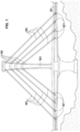
- FIG. 1 shows a cable-stayed bridge where the teachings of the present invention in accordance with the present invention can be applied.
- a cable-stayed bridge generally includes:
- Each stay cable 105 extends between two deck anchorages 107, situated on the deck 101, in such a way that each stay cable 105 traverses a strand guiding device 109, hereinafter referred to as a bridge saddle, situated in the upper part of the pylon 103.
- the stay cable elements used in the field of construction of cable-stayed or suspension bridges are generally corrosion-protected (for years) by a layer of protective material which can be grease, wax or gel-based, and a sheath surrounding the protective layer.
- a layer of protective material which can be grease, wax or gel-based
- sheath surrounding the protective layer.
- the presence of the protecting layer and of the sheath increases the diameter of the strand.
- the strands are each made up of a multiplicity of wires, generally metallic, but not limited thereto.
- each strand comprises a group of seven wires with a cross section which is inscribed in a circle.
- Each cable 105 usually comprises a plurality of strands.
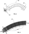
- Figure 2 shows a perspective view of a body 201 of a saddle 109 together with a sealing arrangement or sealing means 202 (not operationally in place in Figure 2 ).
- the saddle is arranged to be traversed longitudinally (following the longitudinal axis of the body) by strands of a stay cable 105.
- Designated by longitudinal axis is a curved path which extends along the longitudinal dimension of the body 201, but not necessarily in the middle position with respect to the outer dimensions of the saddle body 201.
- the bridge anchoring devices 107 are by similar fashion arranged to be traversed by cable strands, so that at one end the strands are anchored.
- the body 201 is a curved rectangular steel box that has a first open end 203 and a second open end 205.
- the cross section of the body 201 could of course be round or shaped in other form to enclose the bundle of strands.
- Figure 3 illustrates a side view of one part of the body 201 in the longitudinal plane.
- the side view of the saddle body 201 shows seven strands 301.
- channels 303 in this example steel tubes (aluminium or plastic tubes are also possible), one tube 303 being provided for each strand 301, and the strands 301 being arranged to traverse the tubes 303 longitudinally.
- Each tube 303 of the body comprises a curved longitudinal axis and at least one first part which, situated in principle at the side of the intrados of the longitudinal axis, permits, within the limit of the length of the tube, the support of the strand 301 on a portion of the peripheral face of the strand 301.
- the tubes 303 follow the curvature of the saddle body 201.
- the sealing arrangement 202 is in place so that the interior part of the body 201 can be sealed off from the outside environment.
- Tube supporting elements 305 are also provided to support the tubes 303 and hold them in place inside the saddle body 201.
- the purpose of the supporting elements 305 is also to support the void formers (in the solution where these are needed) and to take some transverse forces caused by the deviation forces of the curved and stressed strands.
- These supporting elements 305 are arranged to be approximately perpendicular with respect to the tubes 303.
- the part of the strands 301 traversing the tube or channel 303 is not sheathed (the strands being initially sheathed, but the sheath is removed in the region of the saddle as part of the installation process) to increase the friction between the strand 301 and the tube 303.
- This has the advantageous effect of holding the strand 301 in place even when under significant differential tension between the first end 203 and the second end 205.
- the unsheathed strands are susceptible to corrosion, and for this reason protective material may be provided in the saddle body 201 (as will be explained later in more detail) to prevent corrosion from occurring.
- the protective material may be polymeric, wax, grease or gel-based.
- the part of the strand 301 that is not inside the tube 303 is sheathed to provide protection, e.g. against corrosion.
- the sheathing can be made of polyethylene material, for example.
- the space between the individual tubes is advantageously filled with a hardening material such as cementitious mortar.
- Different shapes of the tube cross sections have different clamping effects. For instance, by using V-shaped cross sections at the side of the intrados, a relatively high clamping effect can be obtained. In this case the cross sections of the tube 303 and strand 301 are not of complementary shape.
- each tube 303 each have a cross section of substantially complementary shape to that of the strand 301 which they receive.
- each tube 303 has a cross section substantially circular of an internal diameter greater than the circle in which the cross section of a strand 301 is inscribed in order to facilitate the insertion of the strand 301 through the tube 303.
- the space between the individual tubes is grouted.
- channels are formed inside the saddle body 201 by void formers which are removed after the filler around has hardened. Also in this solution the channels can have a V shape to improve the clamping effect.
- the absence of the metal tubes 303 is even advantageous in the sense that the strands 301 would then not be in contact with metal tubes 303 prone to corrosion or where the contact to metal could cause fretting fatigue to the strand.
- the sealing arrangement 202 in accordance with the present invention allows injecting into the saddle body 201 protective material for protecting the strands 301 and/or the tubes 303 from corrosion.
- the injected protective material can be polymeric material, wax, grease or gel-based, or other similar material, as long this filler keeps oxygen and moisture out of the saddle body 201 and allows removal of the strands 301.
- the polymeric material is obtained by mixing two types of liquids, enabling the polymerisation process to take place.
- the obtained polymeric material is water repellent (does not mix with water), and is only little permeable to gases.
- the injection is advantageously done after mixing of the liquids, before the solidifying (polymerisation) process has properly started. After mixing and injection, the obtained mixture will become solid, but will not harden and thus remains flexible, soft and elastic. Once solidified, the protective filler sticks well to metal surfaces.
- the bridge saddles 109 are often located high above the ground level and for this reason a special arrangement for the injection is needed, as explained below.
- the protective material is advantageously injected into the saddle body 201 through one of the injection tubes 401; 405 located at both ends, at the bottom of the body 201.
- the injection tubes pass through the sealing arrangement 202.
- there are two injection tubes so that the injection is done through one of the injection tubes 401; 405, but it would be also possible to use both injection tubes simultaneously.
- the injection tubes 401; 405 are connected to a filling tank (not shown).
- a first vent 403 and a second vent 407 are shown at the upper part of both ends of the saddle body 201 .
- a vacuum pump not shown.
- the air is first sucked away from the saddle body 201 through one of the vents 403; 407 by using the vacuum pump. This has the effect that all the voids in the interior of the saddle body can be filled with the protective material. In the case where the interior of the saddle body is grouted, then the protective material would fill the space between the strand 301 and the channel wall.
- the protective material injection is done once all the strands 301 (not shown in Figure 4 ) are in place inside the saddle body 201 and stressed.
- the protective material is first injected through one of the injection tubes 401; 405 into a filling chamber 411. From the filling chamber 411 the protective material spreads all around the interior of the saddle body 201 assisted by vacuum application into all individual tubes, and then, some time after completion of injection, it starts solidifying. The injection is stopped once the injected material starts to run out of the saddle body through the vent located at the opposite end.
- the sealing arrangement 202 is provided on both ends of the saddle body 201.
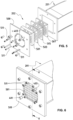
- the sealing arrangement 202 comprises several flat elements, in this example five elements: the outermost element from the body 201 is a front pressing plate 500, the next element being a transition pad 501, the next element being a sealing pad 503, the following being a pressing pad 505, and the element closest to the body 201 is a rear pressing plate 507.
- the pressing pad 505 and the rear pressing plate 507 together can be referred to as a rear pressing element.
- Holes are provided in the transition pad 501, the sealing pad 503, the pressing pad 505 and the rear pressing plate 507 for the strands 301 to pass through.
- the shape of the holes is advantageously complementary to the shape of the strands 301 that pass through these holes to guarantee a good sealing effect. Therefore, the sealing arrangement 202 advantageously makes leak tightness around the strands 301 when the strands 301 traverse the sealing arrangement 202.
- the front pressing element 500 is a rigid element, and in this example it is a steel plate. In the example shown in the figures, there are no holes in the front pressing plate 500 for the strands to pass through to prevent any contact of steel strand to steel plate, but a solution with holes for the strands 301 is also possible. However, holes are provided for tightening means to pass through for pressing the transition pad 501, the sealing pad 503, the rear pressing pad 505 and the rear pressing plate 507 against the front pressing plate 500.
- the transition pad 501 is deformable, and can be made of polyethylene, for instance, and its primary function is to take transverse deviation forces from the strands and to dampen the movements of the strands 301, but its function is also to seal and protect.
- the width of the transition pad 501 is larger than the width of the other elements of the sealing arrangement 202.
- the width of the transition pad 501 can be two or three times the width of the sealing pad 503, for instance. This has the advantageous effect of resisting relatively large deviation forces and of dampening relatively strong strand 301 movements.
- the holes that pass through the transition pad 501, the sealing pad 503, the pressing pad 505 and the pressing plate 507 have a chamfered end where the transition pad 501 is pressed against the front pressing plate 500.
- the chamfer angle can be a few degrees, e.g. 2 degrees. This further facilitates the movements of the strands 301 without bearing against a sharp edge.
- the chamfer angle is also useful if the strands 301 are deviated intentionally.
- the transition pad 501 may undergo elastic deformation. This type of deformation is reversible. In other words, once the forces are no longer applied, the transition pad 501 returns to its original shape. Thus, it provides a smooth transition zone for the strands 301 that traverse the sealing arrangement 202 without creating a hard spot which could damage the strand.
- the primary function of the non-rigid sealing pad 503 is to seal the interior of the saddle body 201 from the outside environment. This pad ensures that the moisture from the outside of the saddle body 201 cannot penetrate into the interior part of the body 201, and it is also intended to prevent the injected protective material from flowing away from the body 201.
- the sealing pad 503 can be made of neoprene, for instance, such as ethylene propylene diene monomer rubber.
- the actual sealing is made by compression of the sealing pad 503 between the transition pad 501 and the pressing pad 505, both advantageously made of polyethylene.
- the rigid pressing pad 505 made for instance of polyethylene or polypropylene, is used together with the rigid steel rear pressing plate 507 to compress the transition pad 501 and the sealing pad 503 against the front pressing plate 500.
- screws 511 or corresponding tightening means are provided to provide sufficient compression.
- the pressing pad 505 and the rear pressing plate 507 also act as a spacer for the strands 301.
- the saddle 109 is first installed onto a bridge pylon 103 with sealing 202 pre-installed but not tightened.
- the strands 301 are then threaded through the saddle body 201. After this, the strands 301 can be stressed, and the transition pad 501 and the sealing pad 503 are compressed between the front pressing plate 500 and the rear pressing element. Then the protective material can be injected into the saddle body 201.
Landscapes
- Engineering & Computer Science (AREA)
- Architecture (AREA)
- Civil Engineering (AREA)
- Structural Engineering (AREA)
- Bridges Or Land Bridges (AREA)
- Building Environments (AREA)
Claims (11)
- Dichtungsanordnung (202) für ein Bauelement, wobei das Bauelement ein Brückensattel (109) mit Zuggliedern (301) ist, wobei die Dichtungsanordnung (202) so angeordnet ist, dass sie einen inneren Teil des Bauelements (109) abdichtet, wobei das Dichtungselement (202) umfasst:- ein Dichtkissen (503) aus elastischem Material; und- ein Druckelement (505 ; 507), umfassend eine starre Schicht,wobei das Dichtkissen (503) und das Druckelement (505; 507) mit Löchern zum Durchführen der Zugglieder (301) versehen sind, und wobei das Dichtkissen (503) und das Druckelement (505; 507) zusammengepresst werden, dadurch gekennzeichnet, dass die Dichtungsanordnung (202) ferner ein Übergangskissen (501) aus einem verformbaren Material umfasst, welches mit Löchern zum Durchführen der Zugglieder (301) versehen ist, wobei das Dichtkissen (503) zwischen dem Übergangskissen (501) und dem Druckelement (505; 507) zusammengepresst ist, wobei zumindest eines der Löcher des Übergangskissens (501) ein abgeschrägtes Ende hat, wobei das Übergangskissen (501) angeordnet ist, um Umlenkkräfte zu unterstützen und/oder Bewegungen der Zugglieder (301) zu dämpfen.
- Dichtungsanordnung (202) nach Anspruch 1, wobei das Druckelement (505; 507) ein Druckkissen (505) aus starrem Material und eine Druckplatte (507) aus starrem Material umfasst.
- Dichtungsanordnung (202) nach Anspruch 2, wobei das Druckkissen (505) aus Polyethylen oder Polypropylen gefertigt ist und die Druckplatte (507) aus Stahl gefertigt ist.
- Dichtungsanordnung (202) nach einem der vorhergehenden Ansprüche, ferner umfassend ein weiteres Druckelement (500), welches gegen das Übergangskissen (501) drückt.
- Dichtungsanordnung (202) nach Anspruch 4, wobei das weitere Druckelement (500) eine flache Platte aus Stahl ist.
- Dichtungsanordnung (202) nach einem der vorhergehenden Ansprüche, wobei das Übergangskissen (501) aus Polyethylen oder auch Polypropylen gefertigt ist.
- Dichtungsanordnung (202) nach einem der vorhergehenden Ansprüche, wobei das Dichtkissen (503) aus Neopren gefertigt ist.
- Dichtungsanordnung (202) nach Anspruch 7, wobei das Neopren Ethylen-Propylen-Dien-Monomer-Kautschuk ist.
- Dichtungsanordnung (202) nach einem der vorhergehenden Ansprüche, weiter umfassend mindestens ein Injektionsrohr (401; 405), welches durch das Übergangskissen (501), das Dichtkissen (503) und dem Druckelement (505; 507) verläuft, um Korrosionsschutzmittel in das Bauelement (107; 109) einzupressen.
- Dichtungsanordnung (202) nach einem der vorhergehenden Ansprüche, weiter umfassend mindestens eine Entlüftung (403; 407), welche durch das Übergangskissen (501), das Dichtkissen (503) und dem Druckelement (505; 507) verläuft, um Luft aus dem Bauelement (109) zu saugen und um Füllmasse während dem Einspritzen zu entlüften.
- Bauelement, wobei das Bauelement ein Brückensattel (109) ist, umfassend die Dichtungsanordnung (202) nach einem der vorhergehenden Ansprüche, wobei das Bauelement (109) einen Körper (201) mit einem offenen Ende (203; 205) aufweist, die Dichtungsanordnung (202) an dem offenen Ende (203; 205) des Körpers (201) angeordnet ist, das Druckelement (505; 507) dem Körper (201) am nächsten ist, und wobei der Körper (201) eine Einspritzkammer (411) umfasst, um Korrosionsschutzmittel aufzunehmen, welches in die Kammer durch das Einspritzrohr (401; 405) eingespritzt wird, welches durch das Übergangskissen (501), das Dichtkissen (503) und dem Druckelement (505; 507) verläuft.
Applications Claiming Priority (1)
| Application Number | Priority Date | Filing Date | Title |
|---|---|---|---|
| PCT/EP2010/053975 WO2011116828A1 (en) | 2010-03-26 | 2010-03-26 | Sealing arrangement |
Publications (3)
| Publication Number | Publication Date |
|---|---|
| EP2550400A1 EP2550400A1 (de) | 2013-01-30 |
| EP2550400B1 EP2550400B1 (de) | 2020-06-24 |
| EP2550400B2 true EP2550400B2 (de) | 2023-06-14 |
Family
ID=43530022
Family Applications (1)
| Application Number | Title | Priority Date | Filing Date |
|---|---|---|---|
| EP10710851.6A Active EP2550400B2 (de) | 2010-03-26 | 2010-03-26 | Dichtungsanordnung |
Country Status (9)
| Country | Link |
|---|---|
| US (1) | US8869476B2 (de) |
| EP (1) | EP2550400B2 (de) |
| JP (1) | JP5567205B2 (de) |
| KR (1) | KR101735088B1 (de) |
| CN (1) | CN102939420B (de) |
| BR (1) | BR112012023677B1 (de) |
| ES (1) | ES2813062T5 (de) |
| RU (1) | RU2515660C1 (de) |
| WO (1) | WO2011116828A1 (de) |
Families Citing this family (16)
| Publication number | Priority date | Publication date | Assignee | Title |
|---|---|---|---|---|
| DE102011106431B3 (de) * | 2011-07-04 | 2012-10-25 | Dywidag-Systems International Gmbh | Anordnung zum Abstützen eines Zugglieds, insbesondere eines Schrägseils, quer zu seiner Längserstreckungsrichtung |
| US20140083031A1 (en) * | 2012-08-24 | 2014-03-27 | Ronald Lindsay Dunlop | Void former and method of reinforcing |
| EP2703331B1 (de) * | 2012-09-03 | 2014-12-24 | Soletanche Freyssinet | Traktionssystem unter Verwendung eines mehrsehnigen Kabels mit einem Ablenkungswinkel |
| GB2514621B (en) | 2013-05-31 | 2020-04-15 | Vsl Int Ag | Cable anchorage |
| KR101530643B1 (ko) * | 2013-06-18 | 2015-06-22 | 주식회사 후레씨네코리아 | 교량주탑용 새들 및 이를 이용한 케이블 정착방법 |
| DE102013215136A1 (de) * | 2013-08-01 | 2015-02-05 | Dywidag-Systems International Gmbh | Korrosionsgeschütztes Zugglied und plastisch verformbare Scheibe aus Korrosionsschutzmaterial für ein derartiges Zugglied |
| ES2589038B1 (es) * | 2015-05-04 | 2017-09-08 | Técnicas Del Pretensado Y Servicios Auxiliares, S.L. | Desviador para postesado exterior de viaductos y procedimiento para su fabricación |
| WO2017002069A1 (en) | 2015-07-01 | 2017-01-05 | Vsl International Ag | Anchorage assembly for a structure, concrete structure with such an assembly, and manufacturing method of such a concrete structure |
| CN105780652B (zh) * | 2016-04-25 | 2018-03-30 | 安徽省公路桥梁工程有限公司 | 一种密封装置、应用该装置的索鞍密封连接结构及施工方法 |
| CN106087743B (zh) * | 2016-07-29 | 2018-11-13 | 安徽金星预应力工程技术有限公司 | 一种水滴型鞍座端部密封装置 |
| FR3069555A1 (fr) * | 2017-07-28 | 2019-02-01 | Soletanche Freyssinet | Ensemble ameliore comprenant un cable de structure et un dispositif de deviation |
| KR101974516B1 (ko) * | 2018-11-26 | 2019-05-03 | 주식회사 한국교량 | 볼조인트 카르단과 웨지정착구를 이용한 케이블 정착장치 및 그 시공방법 |
| KR102013736B1 (ko) * | 2018-12-17 | 2019-08-23 | 박무수 | 볼조인트 카르단을 이용한 케이블 정착장치 및 이를 이용한 케이블 스트랜드 교체방법 |
| CN111041970B (zh) * | 2019-12-17 | 2021-03-16 | 北京市第三建筑工程有限公司 | 预应力单耳拉索及其张拉方法 |
| AU2022398488A1 (en) * | 2021-11-24 | 2024-06-13 | Felix Sorkin | Polymer blend cradle for cable-stayed bridge |
| US12054947B1 (en) * | 2024-01-08 | 2024-08-06 | King Faisal University | Multi-layer wedge anchorage for FRP plates and FRP tendons |
Citations (2)
| Publication number | Priority date | Publication date | Assignee | Title |
|---|---|---|---|---|
| JPH0874937A (ja) † | 1994-09-06 | 1996-03-19 | S Ii:Kk | ケーブルの定着方法とその装置 |
| JPH08302904A (ja) † | 1995-05-01 | 1996-11-19 | Sumitomo Electric Ind Ltd | Pc鋼より線群よりなるマルチストランドケーブルの部分液密構造 |
Family Cites Families (29)
| Publication number | Priority date | Publication date | Assignee | Title |
|---|---|---|---|---|
| US2755657A (en) * | 1951-11-29 | 1956-07-24 | Finsterwalder Ulrich | Post-stressed reinforcing rod anchor |
| GB1125176A (en) * | 1966-03-31 | 1968-08-28 | P S C Equipment Ltd | A new or improved system for securing wires in a stressed condition |
| US3437359A (en) * | 1968-04-03 | 1969-04-08 | Western Concrete Structures Co | Post tensioning concrete anchor assembly |
| US3787957A (en) * | 1971-07-06 | 1974-01-29 | American Stress Wire Corp | Method and apparatus for tensioning and anchoring tensioning members |
| US4237942A (en) * | 1975-11-21 | 1980-12-09 | Hans Dietrich | Apparatus to produce an anchor on a tendon twisted of several steel wires |
| EP0025856B1 (de) * | 1979-08-13 | 1984-07-25 | RESTRA-Patentverwertung GmbH | Vorrichtung zur Endverankerung mindestens eines als Spannglied im Spannbetonbau eingesetzten Stabes aus Faser-Verbundstoff |
| FR2511721A1 (fr) * | 1981-08-21 | 1983-02-25 | Freyssinet Int Stup | Dispositif de raccordement incurve entre deux portions rectilignes d'un cable tendu |
| GB8327978D0 (en) * | 1983-10-19 | 1983-11-23 | Manuf Aceros Caucho Sa | Cable anchorage |
| FR2623551B1 (fr) * | 1987-11-25 | 1992-04-24 | Freyssinet Int Stup | Perfectionnements aux haubans et a leurs composants |
| FR2656883B1 (fr) | 1990-01-11 | 1992-08-28 | Freyssinet Int Stup | Perfectionnements aux ponts a haubans et plus particulierement a leurs haubans, pylones et tabliers. |
| FR2663975B1 (fr) * | 1990-06-29 | 1993-07-09 | Freyssinet Int Stup | Perfectionnements aux ponts a haubans et plus particulierement a leurs pylones et haubans. |
| KR100213395B1 (ko) * | 1991-04-02 | 1999-08-02 | 더블유. 알. 에섹스, 윌리암 알. 에섹스, 메리 앤 터커 | 이음애 밀봉용 복합 가스켓 및 이의 제조방법, 그리고 이러한 가스켓을 갖춘 창문 구조물 |
| DE4433832A1 (de) | 1994-09-22 | 1996-03-28 | Dyckerhoff & Widmann Ag | Korrosionsgeschütztes Zugglied, vornehmlich Spannglied für Spannbeton ohne Verbund |
| DE19536701C2 (de) * | 1995-09-30 | 1999-07-15 | Dyckerhoff & Widmann Ag | Verfahren zum Spannen eines Zugglieds aus einer Mehrzahl von Einzelelementen |
| JP3373426B2 (ja) * | 1998-03-31 | 2003-02-04 | 神鋼鋼線工業株式会社 | 斜張橋ケーブル用サドル構造体 |
| CN1287202A (zh) * | 1999-09-03 | 2001-03-14 | 柳州欧维姆建筑机械有限公司 | 真空灌浆法及其密封锚索 |
| FR2798410B1 (fr) | 1999-09-15 | 2001-11-23 | Freyssinet Int Stup | Dispositif d'ancrage pour fixer un cable de structure a un element de construction |
| CN2393907Y (zh) * | 1999-11-10 | 2000-08-30 | 柳州市建筑机械总厂 | 斜拉索减振装置 |
| FR2806107B1 (fr) * | 2000-03-13 | 2002-10-11 | Freyssinet Int Stup | Selle de deviation pour cable et structure de genie civil comprenant une telle selle de deviation |
| FR2806428B1 (fr) * | 2000-03-14 | 2002-05-31 | Freyssinet Int Stup | Procede pour ancrer un nouveau cable a un massif d'ancrage preexistant sur lequel est deja ancre un cable d'origine |
| ES2307580T3 (es) * | 2001-01-29 | 2008-12-01 | Vsl International Ag | Dispositivo y metodo para anclaje de un extremo de un tirante a una base. |
| DE20205149U1 (de) * | 2002-04-03 | 2002-07-04 | DYWIDAG-Systems International GmbH, 85609 Aschheim | Korrosionsgeschütztes Zugglied, insbesondere Schrägseil für eine Schrägseilbrücke |
| EP1435413A1 (de) * | 2002-12-30 | 2004-07-07 | Yincheng Hou | Verankerungsvorrichtung für Schrägseilsystem |
| CN2604463Y (zh) * | 2003-02-28 | 2004-02-25 | 中国水利水电科学研究院 | 防水型外锚固端 |
| DE20311950U1 (de) * | 2003-08-02 | 2004-12-09 | Dywidag-Systems International Gmbh | Korrosionsgeschütztes Zugglied, insbesondere Spannglied für Spannbeton |
| CN2673945Y (zh) * | 2003-11-22 | 2005-01-26 | 柳州欧维姆机械股份有限公司 | 具有锚下柔性自密封结构的岩土防腐锚索 |
| JP2005171604A (ja) * | 2003-12-10 | 2005-06-30 | Anderson Technology Kk | Pc構造物の外ケーブルの防食構造 |
| KR100736774B1 (ko) * | 2006-05-30 | 2007-07-09 | 주식회사신화기공 | 타이케이블의 제작방법 |
| CN201296899Y (zh) * | 2008-06-16 | 2009-08-26 | 江阴法尔胜住电新材料有限公司 | 锚具防腐结构 |
-
2010
- 2010-03-26 EP EP10710851.6A patent/EP2550400B2/de active Active
- 2010-03-26 KR KR1020127025095A patent/KR101735088B1/ko active Active
- 2010-03-26 RU RU2012145670/03A patent/RU2515660C1/ru active
- 2010-03-26 US US13/581,547 patent/US8869476B2/en active Active
- 2010-03-26 BR BR112012023677-6A patent/BR112012023677B1/pt active IP Right Grant
- 2010-03-26 WO PCT/EP2010/053975 patent/WO2011116828A1/en not_active Ceased
- 2010-03-26 CN CN201080065806.9A patent/CN102939420B/zh active Active
- 2010-03-26 JP JP2013500343A patent/JP5567205B2/ja active Active
- 2010-03-26 ES ES10710851T patent/ES2813062T5/es active Active
Patent Citations (2)
| Publication number | Priority date | Publication date | Assignee | Title |
|---|---|---|---|---|
| JPH0874937A (ja) † | 1994-09-06 | 1996-03-19 | S Ii:Kk | ケーブルの定着方法とその装置 |
| JPH08302904A (ja) † | 1995-05-01 | 1996-11-19 | Sumitomo Electric Ind Ltd | Pc鋼より線群よりなるマルチストランドケーブルの部分液密構造 |
Also Published As
| Publication number | Publication date |
|---|---|
| EP2550400B1 (de) | 2020-06-24 |
| JP2013524040A (ja) | 2013-06-17 |
| JP5567205B2 (ja) | 2014-08-06 |
| BR112012023677B1 (pt) | 2022-03-15 |
| ES2813062T3 (es) | 2021-03-22 |
| RU2515660C1 (ru) | 2014-05-20 |
| US20130186019A1 (en) | 2013-07-25 |
| BR112012023677A2 (pt) | 2021-08-17 |
| EP2550400A1 (de) | 2013-01-30 |
| HK1178226A1 (zh) | 2013-09-06 |
| US8869476B2 (en) | 2014-10-28 |
| WO2011116828A1 (en) | 2011-09-29 |
| CN102939420B (zh) | 2016-06-08 |
| RU2012145670A (ru) | 2014-05-10 |
| KR101735088B1 (ko) | 2017-05-12 |
| ES2813062T5 (en) | 2025-03-07 |
| KR20130038819A (ko) | 2013-04-18 |
| CN102939420A (zh) | 2013-02-20 |
Similar Documents
| Publication | Publication Date | Title |
|---|---|---|
| EP2550400B2 (de) | Dichtungsanordnung | |
| EP2550401B1 (de) | Sattelsteg und verfahren zum schutz der stränge von korrosion in diesem sattelsteg | |
| EP3004461B1 (de) | Kabelverankerung mit einbettungsmaterial | |
| JP6684838B2 (ja) | プレストレス沈埋函構造及びその施工方法 | |
| TR201808886T4 (tr) | Öngerilmeli diyafram duvar ve bu tür bir duvarı gerçekleştirme yöntemi. | |
| KR20110111907A (ko) | 사장교 주탑쪽의 사장 케이블용 새들 구조체 | |
| KR101546844B1 (ko) | 케이블의 정착장치 | |
| CN106120557B (zh) | 桥托架以及用于保护线股免于在桥托架中腐蚀的方法 | |
| HK1178226B (en) | Sealing arrangement | |
| JP2015042844A (ja) | 撚線案内装置の改善 | |
| HK1177775A (en) | Improvement for a strand guiding device | |
| HK1231148A (en) | Improvement for a strand guiding device | |
| HK1231148A1 (en) | Bridge support frame and method for protecting strand from corroding in the same | |
| WO2025195610A1 (en) | Improvement of a strand guiding device and deviation pad | |
| HK1231148B (zh) | 桥托架以及用於保护线股免於在桥托架中腐蚀的方法 | |
| KR20090021322A (ko) | 프리스트레스트 콘크리트 거더용 강선의 보호홀더 및 이를이용한 강선의 삽입방법 | |
| KR20090115695A (ko) | 프리스트레스트 콘크리트 거더용 강선의 보호홀더 | |
| HK1220498B (en) | Cable anchorage with bedding material |
Legal Events
| Date | Code | Title | Description |
|---|---|---|---|
| PUAI | Public reference made under article 153(3) epc to a published international application that has entered the european phase |
Free format text: ORIGINAL CODE: 0009012 |
|
| 17P | Request for examination filed |
Effective date: 20120817 |
|
| AK | Designated contracting states |
Kind code of ref document: A1 Designated state(s): AT BE BG CH CY CZ DE DK EE ES FI FR GB GR HR HU IE IS IT LI LT LU LV MC MK MT NL NO PL PT RO SE SI SK SM TR |
|
| DAX | Request for extension of the european patent (deleted) | ||
| 17Q | First examination report despatched |
Effective date: 20130923 |
|
| RAP1 | Party data changed (applicant data changed or rights of an application transferred) |
Owner name: VSL INTERNATIONAL AG |
|
| STAA | Information on the status of an ep patent application or granted ep patent |
Free format text: STATUS: EXAMINATION IS IN PROGRESS |
|
| GRAP | Despatch of communication of intention to grant a patent |
Free format text: ORIGINAL CODE: EPIDOSNIGR1 |
|
| STAA | Information on the status of an ep patent application or granted ep patent |
Free format text: STATUS: GRANT OF PATENT IS INTENDED |
|
| INTG | Intention to grant announced |
Effective date: 20200220 |
|
| GRAS | Grant fee paid |
Free format text: ORIGINAL CODE: EPIDOSNIGR3 |
|
| GRAA | (expected) grant |
Free format text: ORIGINAL CODE: 0009210 |
|
| STAA | Information on the status of an ep patent application or granted ep patent |
Free format text: STATUS: THE PATENT HAS BEEN GRANTED |
|
| AK | Designated contracting states |
Kind code of ref document: B1 Designated state(s): AT BE BG CH CY CZ DE DK EE ES FI FR GB GR HR HU IE IS IT LI LT LU LV MC MK MT NL NO PL PT RO SE SI SK SM TR |
|
| REG | Reference to a national code |
Ref country code: GB Ref legal event code: FG4D |
|
| REG | Reference to a national code |
Ref country code: CH Ref legal event code: EP |
|
| REG | Reference to a national code |
Ref country code: AT Ref legal event code: REF Ref document number: 1284020 Country of ref document: AT Kind code of ref document: T Effective date: 20200715 |
|
| REG | Reference to a national code |
Ref country code: DE Ref legal event code: R096 Ref document number: 602010064714 Country of ref document: DE |
|
| REG | Reference to a national code |
Ref country code: IE Ref legal event code: FG4D |
|
| REG | Reference to a national code |
Ref country code: CH Ref legal event code: NV Representative=s name: BOVARD AG PATENT- UND MARKENANWAELTE, CH |
|
| PG25 | Lapsed in a contracting state [announced via postgrant information from national office to epo] |
Ref country code: LT Free format text: LAPSE BECAUSE OF FAILURE TO SUBMIT A TRANSLATION OF THE DESCRIPTION OR TO PAY THE FEE WITHIN THE PRESCRIBED TIME-LIMIT Effective date: 20200624 Ref country code: NO Free format text: LAPSE BECAUSE OF FAILURE TO SUBMIT A TRANSLATION OF THE DESCRIPTION OR TO PAY THE FEE WITHIN THE PRESCRIBED TIME-LIMIT Effective date: 20200924 Ref country code: GR Free format text: LAPSE BECAUSE OF FAILURE TO SUBMIT A TRANSLATION OF THE DESCRIPTION OR TO PAY THE FEE WITHIN THE PRESCRIBED TIME-LIMIT Effective date: 20200925 Ref country code: SE Free format text: LAPSE BECAUSE OF FAILURE TO SUBMIT A TRANSLATION OF THE DESCRIPTION OR TO PAY THE FEE WITHIN THE PRESCRIBED TIME-LIMIT Effective date: 20200624 Ref country code: FI Free format text: LAPSE BECAUSE OF FAILURE TO SUBMIT A TRANSLATION OF THE DESCRIPTION OR TO PAY THE FEE WITHIN THE PRESCRIBED TIME-LIMIT Effective date: 20200624 |
|
| REG | Reference to a national code |
Ref country code: LT Ref legal event code: MG4D |
|
| PG25 | Lapsed in a contracting state [announced via postgrant information from national office to epo] |
Ref country code: HR Free format text: LAPSE BECAUSE OF FAILURE TO SUBMIT A TRANSLATION OF THE DESCRIPTION OR TO PAY THE FEE WITHIN THE PRESCRIBED TIME-LIMIT Effective date: 20200624 Ref country code: LV Free format text: LAPSE BECAUSE OF FAILURE TO SUBMIT A TRANSLATION OF THE DESCRIPTION OR TO PAY THE FEE WITHIN THE PRESCRIBED TIME-LIMIT Effective date: 20200624 Ref country code: BG Free format text: LAPSE BECAUSE OF FAILURE TO SUBMIT A TRANSLATION OF THE DESCRIPTION OR TO PAY THE FEE WITHIN THE PRESCRIBED TIME-LIMIT Effective date: 20200924 |
|
| REG | Reference to a national code |
Ref country code: NL Ref legal event code: MP Effective date: 20200624 |
|
| REG | Reference to a national code |
Ref country code: AT Ref legal event code: MK05 Ref document number: 1284020 Country of ref document: AT Kind code of ref document: T Effective date: 20200624 |
|
| PG25 | Lapsed in a contracting state [announced via postgrant information from national office to epo] |
Ref country code: NL Free format text: LAPSE BECAUSE OF FAILURE TO SUBMIT A TRANSLATION OF THE DESCRIPTION OR TO PAY THE FEE WITHIN THE PRESCRIBED TIME-LIMIT Effective date: 20200624 |
|
| PG25 | Lapsed in a contracting state [announced via postgrant information from national office to epo] |
Ref country code: EE Free format text: LAPSE BECAUSE OF FAILURE TO SUBMIT A TRANSLATION OF THE DESCRIPTION OR TO PAY THE FEE WITHIN THE PRESCRIBED TIME-LIMIT Effective date: 20200624 Ref country code: SM Free format text: LAPSE BECAUSE OF FAILURE TO SUBMIT A TRANSLATION OF THE DESCRIPTION OR TO PAY THE FEE WITHIN THE PRESCRIBED TIME-LIMIT Effective date: 20200624 Ref country code: RO Free format text: LAPSE BECAUSE OF FAILURE TO SUBMIT A TRANSLATION OF THE DESCRIPTION OR TO PAY THE FEE WITHIN THE PRESCRIBED TIME-LIMIT Effective date: 20200624 Ref country code: PT Free format text: LAPSE BECAUSE OF FAILURE TO SUBMIT A TRANSLATION OF THE DESCRIPTION OR TO PAY THE FEE WITHIN THE PRESCRIBED TIME-LIMIT Effective date: 20201026 Ref country code: CZ Free format text: LAPSE BECAUSE OF FAILURE TO SUBMIT A TRANSLATION OF THE DESCRIPTION OR TO PAY THE FEE WITHIN THE PRESCRIBED TIME-LIMIT Effective date: 20200624 Ref country code: AT Free format text: LAPSE BECAUSE OF FAILURE TO SUBMIT A TRANSLATION OF THE DESCRIPTION OR TO PAY THE FEE WITHIN THE PRESCRIBED TIME-LIMIT Effective date: 20200624 |
|
| PG25 | Lapsed in a contracting state [announced via postgrant information from national office to epo] |
Ref country code: SK Free format text: LAPSE BECAUSE OF FAILURE TO SUBMIT A TRANSLATION OF THE DESCRIPTION OR TO PAY THE FEE WITHIN THE PRESCRIBED TIME-LIMIT Effective date: 20200624 Ref country code: PL Free format text: LAPSE BECAUSE OF FAILURE TO SUBMIT A TRANSLATION OF THE DESCRIPTION OR TO PAY THE FEE WITHIN THE PRESCRIBED TIME-LIMIT Effective date: 20200624 Ref country code: IS Free format text: LAPSE BECAUSE OF FAILURE TO SUBMIT A TRANSLATION OF THE DESCRIPTION OR TO PAY THE FEE WITHIN THE PRESCRIBED TIME-LIMIT Effective date: 20201024 |
|
| REG | Reference to a national code |
Ref country code: DE Ref legal event code: R026 Ref document number: 602010064714 Country of ref document: DE |
|
| PLBI | Opposition filed |
Free format text: ORIGINAL CODE: 0009260 |
|
| REG | Reference to a national code |
Ref country code: ES Ref legal event code: FG2A Ref document number: 2813062 Country of ref document: ES Kind code of ref document: T3 Effective date: 20210322 |
|
| PLAX | Notice of opposition and request to file observation + time limit sent |
Free format text: ORIGINAL CODE: EPIDOSNOBS2 |
|
| 26 | Opposition filed |
Opponent name: DYWIDAG-SYSTEMS INTERNATIONAL GMBH Effective date: 20210302 |
|
| PG25 | Lapsed in a contracting state [announced via postgrant information from national office to epo] |
Ref country code: DK Free format text: LAPSE BECAUSE OF FAILURE TO SUBMIT A TRANSLATION OF THE DESCRIPTION OR TO PAY THE FEE WITHIN THE PRESCRIBED TIME-LIMIT Effective date: 20200624 |
|
| PLBB | Reply of patent proprietor to notice(s) of opposition received |
Free format text: ORIGINAL CODE: EPIDOSNOBS3 |
|
| PG25 | Lapsed in a contracting state [announced via postgrant information from national office to epo] |
Ref country code: SI Free format text: LAPSE BECAUSE OF FAILURE TO SUBMIT A TRANSLATION OF THE DESCRIPTION OR TO PAY THE FEE WITHIN THE PRESCRIBED TIME-LIMIT Effective date: 20200624 |
|
| PG25 | Lapsed in a contracting state [announced via postgrant information from national office to epo] |
Ref country code: MC Free format text: LAPSE BECAUSE OF FAILURE TO SUBMIT A TRANSLATION OF THE DESCRIPTION OR TO PAY THE FEE WITHIN THE PRESCRIBED TIME-LIMIT Effective date: 20200624 |
|
| GBPC | Gb: european patent ceased through non-payment of renewal fee |
Effective date: 20210326 |
|
| REG | Reference to a national code |
Ref country code: BE Ref legal event code: MM Effective date: 20210331 |
|
| PG25 | Lapsed in a contracting state [announced via postgrant information from national office to epo] |
Ref country code: LU Free format text: LAPSE BECAUSE OF NON-PAYMENT OF DUE FEES Effective date: 20210326 Ref country code: IE Free format text: LAPSE BECAUSE OF NON-PAYMENT OF DUE FEES Effective date: 20210326 Ref country code: GB Free format text: LAPSE BECAUSE OF NON-PAYMENT OF DUE FEES Effective date: 20210326 |
|
| PG25 | Lapsed in a contracting state [announced via postgrant information from national office to epo] |
Ref country code: BE Free format text: LAPSE BECAUSE OF NON-PAYMENT OF DUE FEES Effective date: 20210331 |
|
| PUAH | Patent maintained in amended form |
Free format text: ORIGINAL CODE: 0009272 |
|
| STAA | Information on the status of an ep patent application or granted ep patent |
Free format text: STATUS: PATENT MAINTAINED AS AMENDED |
|
| PG25 | Lapsed in a contracting state [announced via postgrant information from national office to epo] |
Ref country code: HU Free format text: LAPSE BECAUSE OF FAILURE TO SUBMIT A TRANSLATION OF THE DESCRIPTION OR TO PAY THE FEE WITHIN THE PRESCRIBED TIME-LIMIT; INVALID AB INITIO Effective date: 20100326 Ref country code: CY Free format text: LAPSE BECAUSE OF FAILURE TO SUBMIT A TRANSLATION OF THE DESCRIPTION OR TO PAY THE FEE WITHIN THE PRESCRIBED TIME-LIMIT Effective date: 20200624 |
|
| 27A | Patent maintained in amended form |
Effective date: 20230614 |
|
| AK | Designated contracting states |
Kind code of ref document: B2 Designated state(s): AT BE BG CH CY CZ DE DK EE ES FI FR GB GR HR HU IE IS IT LI LT LU LV MC MK MT NL NO PL PT RO SE SI SK SM TR |
|
| REG | Reference to a national code |
Ref country code: DE Ref legal event code: R102 Ref document number: 602010064714 Country of ref document: DE |
|
| PG25 | Lapsed in a contracting state [announced via postgrant information from national office to epo] |
Ref country code: ES Free format text: LAPSE BECAUSE OF FAILURE TO SUBMIT A TRANSLATION OF THE DESCRIPTION OR TO PAY THE FEE WITHIN THE PRESCRIBED TIME-LIMIT Effective date: 20230614 |
|
| PG25 | Lapsed in a contracting state [announced via postgrant information from national office to epo] |
Ref country code: MK Free format text: LAPSE BECAUSE OF FAILURE TO SUBMIT A TRANSLATION OF THE DESCRIPTION OR TO PAY THE FEE WITHIN THE PRESCRIBED TIME-LIMIT Effective date: 20200624 |
|
| PG25 | Lapsed in a contracting state [announced via postgrant information from national office to epo] |
Ref country code: TR Free format text: LAPSE BECAUSE OF FAILURE TO SUBMIT A TRANSLATION OF THE DESCRIPTION OR TO PAY THE FEE WITHIN THE PRESCRIBED TIME-LIMIT Effective date: 20200624 |
|
| PG25 | Lapsed in a contracting state [announced via postgrant information from national office to epo] |
Ref country code: MT Free format text: LAPSE BECAUSE OF FAILURE TO SUBMIT A TRANSLATION OF THE DESCRIPTION OR TO PAY THE FEE WITHIN THE PRESCRIBED TIME-LIMIT Effective date: 20200624 |
|
| REG | Reference to a national code |
Ref country code: ES Ref legal event code: NE2A Effective date: 20250228 |
|
| REG | Reference to a national code |
Ref country code: ES Ref legal event code: DC2A Ref document number: 2813062 Country of ref document: ES Kind code of ref document: T5 Effective date: 20250307 |
|
| PG25 | Lapsed in a contracting state [announced via postgrant information from national office to epo] |
Ref country code: ES Free format text: LAPSE BECAUSE OF FAILURE TO SUBMIT A TRANSLATION OF THE DESCRIPTION OR TO PAY THE FEE WITHIN THE PRESCRIBED TIME-LIMIT Effective date: 20230614 |
|
| PGRI | Patent reinstated in contracting state [announced from national office to epo] |
Ref country code: ES Effective date: 20250228 |
|
| PGFP | Annual fee paid to national office [announced via postgrant information from national office to epo] |
Ref country code: ES Payment date: 20250425 Year of fee payment: 16 |
|
| PGFP | Annual fee paid to national office [announced via postgrant information from national office to epo] |
Ref country code: CH Payment date: 20250401 Year of fee payment: 16 |
|
| REG | Reference to a national code |
Ref country code: CH Ref legal event code: U11 Free format text: ST27 STATUS EVENT CODE: U-0-0-U10-U11 (AS PROVIDED BY THE NATIONAL OFFICE) Effective date: 20260401 |
|
| PGFP | Annual fee paid to national office [announced via postgrant information from national office to epo] |
Ref country code: DE Payment date: 20260319 Year of fee payment: 17 |
|
| PGFP | Annual fee paid to national office [announced via postgrant information from national office to epo] |
Ref country code: IT Payment date: 20260319 Year of fee payment: 17 |
|
| PGFP | Annual fee paid to national office [announced via postgrant information from national office to epo] |
Ref country code: FR Payment date: 20260320 Year of fee payment: 17 |