EP2551097A1 - Presse à poudre - Google Patents
Presse à poudre Download PDFInfo
- Publication number
- EP2551097A1 EP2551097A1 EP11175810A EP11175810A EP2551097A1 EP 2551097 A1 EP2551097 A1 EP 2551097A1 EP 11175810 A EP11175810 A EP 11175810A EP 11175810 A EP11175810 A EP 11175810A EP 2551097 A1 EP2551097 A1 EP 2551097A1
- Authority
- EP
- European Patent Office
- Prior art keywords
- action
- drive train
- section
- line
- end portion
- Prior art date
- Legal status (The legal status is an assumption and is not a legal conclusion. Google has not performed a legal analysis and makes no representation as to the accuracy of the status listed.)
- Withdrawn
Links
- 239000000843 powder Substances 0.000 title claims abstract description 53
- 238000003825 pressing Methods 0.000 claims abstract description 32
- 238000005452 bending Methods 0.000 claims abstract description 13
- 238000006073 displacement reaction Methods 0.000 claims description 33
- 238000005096 rolling process Methods 0.000 claims description 5
- 239000013598 vector Substances 0.000 claims description 5
- 239000012254 powdered material Substances 0.000 claims description 4
- 230000000694 effects Effects 0.000 claims description 2
- 230000001050 lubricating effect Effects 0.000 claims description 2
- 239000000463 material Substances 0.000 abstract description 3
- 239000011159 matrix material Substances 0.000 abstract 3
- 239000008188 pellet Substances 0.000 abstract 1
- 230000005540 biological transmission Effects 0.000 description 16
- 238000000034 method Methods 0.000 description 6
- 230000006835 compression Effects 0.000 description 4
- 238000007906 compression Methods 0.000 description 4
- 230000005489 elastic deformation Effects 0.000 description 4
- 230000000875 corresponding effect Effects 0.000 description 3
- 238000006243 chemical reaction Methods 0.000 description 2
- 239000002184 metal Substances 0.000 description 2
- 240000001439 Opuntia Species 0.000 description 1
- 238000010276 construction Methods 0.000 description 1
- 238000004904 shortening Methods 0.000 description 1
Images


Classifications
-
- B—PERFORMING OPERATIONS; TRANSPORTING
- B30—PRESSES
- B30B—PRESSES IN GENERAL
- B30B1/00—Presses, using a press ram, characterised by the features of the drive therefor, pressure being transmitted directly, or through simple thrust or tension members only, to the press ram or platen
- B30B1/40—Presses, using a press ram, characterised by the features of the drive therefor, pressure being transmitted directly, or through simple thrust or tension members only, to the press ram or platen by wedge means
-
- B—PERFORMING OPERATIONS; TRANSPORTING
- B30—PRESSES
- B30B—PRESSES IN GENERAL
- B30B11/00—Presses specially adapted for forming shaped articles from material in particulate or plastic state, e.g. briquetting presses, tabletting presses
- B30B11/02—Presses specially adapted for forming shaped articles from material in particulate or plastic state, e.g. briquetting presses, tabletting presses using a ram exerting pressure on the material in a moulding space
-
- B—PERFORMING OPERATIONS; TRANSPORTING
- B30—PRESSES
- B30B—PRESSES IN GENERAL
- B30B15/00—Details of, or accessories for, presses; Auxiliary measures in connection with pressing
- B30B15/06—Platens or press rams
- B30B15/068—Drive connections, e.g. pivotal
Definitions
- the invention relates to a powder press for producing a compact of a powdery material.
- Such a powder press is provided with a frame, a punch assembly and a die assembly defining a mold cavity into which the powdered material is fillable, and a motor unit operatively connected to the punch assembly and / or to the die assembly via a drive train for forming the compact, the punch arrangement and the die arrangement are movable relative to each other by means of the motor unit via the drive train along a pressing axis and can be pressed against one another.
- At least one punch arrangement and a die arrangement are arranged along the generally vertically extending press axis.
- the invention has for its object to provide a powder press of the type described above, the length or height along the pressing direction compared to the known powder presses is significantly reduced.
- the invention provides a powder press of the type mentioned, in which the extending from the motor unit to the punch assembly and / or the die assembly drive train has a Abwinkelungs Scheme having an angling between a first line of action of a first drive train section extending from the motor unit to the bend and a second line of action of a second drive train section, extending from the bend to the punch assembly and / or to the die assembly.
- a first end section of the first drive train section protruding into the bending zone is displaceably supported by first guide means
- a second end section of the second drive train section protruding into the bending section is along the second effective straight line by means of the second Guide means slidably mounted, and are the first end portion and the second end portion along a third, spatially displaceable, but constantly alignedmessgeraden slidably mounted to each other by third guide means, wherein the third line of action extends along a direction within the of the first line of action and the second effective straight line spanned angle range of the bend between the first drive train section and the second drive train section extends.
- the invention can be realized in a particularly simple manner by using guide means which enable a linear guidance of the movable drive train sections to stationary press parts, in particular directly or indirectly on the frame, and a linear guide of the movable drive train sections together .
- Guide means of identical construction can be used for the first, second and third guide means.
- the first end portion and the second end portion are wedge-shaped to each other.
- the first end portion and the second end portion are slidable along an imaginary, spatially displaceable, but always constantly aligned displacement surface stored, which is generated by means of the third line of action as a generator by transverse displacement thereof.
- the angled force flow transmitted along the drive train and via its angling can be transmitted via the displacement surface, so that the force transmitted per unit area is not too great.
- Another advantage of this angled wedge-like power transmission results from the fact that the first drive train section is guided over the first end portion of a stationary, always spatially always aligned first linear guide that the second drive train section on the second end portion at a stationary, spatially always aligned second linear guide is performed and that the first end portion and the second end portion along a spatially displaceable, but also always spatially aligned third linear guide are performed.
- a motor unit a preferably designed as a hollow shaft motor electric motor can be used, the rotational movement is registered via a spindle / nut arrangement or via a nut / spindle arrangement as a linear movement in the drive train.
- the electric motor is preferably a servomotor.
- the imaginary displacement surface may be part of a plane which contains the third action straight line and extends orthogonal to the plane defined by the first action straight line and the second action straight line.
- the imaginary displacement surface can also be part of the lateral surface of a prism whose longitudinal axis runs parallel to the third effective straight line and whose base surface is in particular circular or polygonal.
- first end portion and the second end portion may be e.g. by means of rolling elements, which are arranged between the first end portion and the second end portion, to be slidably mounted to each other, or they may e.g. by means of a lubricating film, which is arranged between the first end portion and the second end portion to be slidably mounted to each other.
- the bend between the first direction of action and the second direction of action is in an angular range of 60 ° to 120 ° and is preferably 90 °.
- the third direction of action extends within the angle range between the first drive train section and the second drive train section spanned by the first effective straight line and the second effective straight line.
- the latter has two motor units which are in operative connection with the punch arrangement and / or with the die arrangement via a respective drive train; wherein the first driveline extends from the first motor unit to the punch assembly and / or to the die assembly and the second driveline extends from the second motor unit to the punch assembly and / or to the die assembly; wherein the first driveline has a first bend between a straight line of action of a first motor-side driveline section extending from the first motor unit to the first angled section, and a first drive line Action line of a first punch-side and / or die-side drive-train section extending from the first bend to the punch assembly and / or to the die assembly; wherein the second driveline has a second bend between a straight line of action of a second motor side driveline section extending from the second motor unit to the second angled section and a straight line of action of a second punch side and / or die side driveline section extending from the second angled section
- Such a twin-engine or multi-engine design allows compensation of the forces acting inside the drive trains driving forces to the outside.
- the drive forces registered horizontally over the two or more engine units can thus be compensated for by appropriately arranging the two or more motor units outwards, so that no special measures are required for generating external reaction forces, such as e.g. the stiction of the press base on the floor or the fixation of the press frame on a wall, are required.
- the two lines of action of the first and second motor-side driveline sections are collinear and form a common motor action straight line and, in addition, the two lines of action of the first and second punch side and / or die side driveline sections are collinear and form a common punch / die action straight wherein the motor action line and the punch / die action line orthogonally cross each other in the bend region, and wherein the first motor unit is located diametrically opposite this side and the second motor unit beyond the bend region on the common Moror action straight line.
- This design with diametrical drive by means of two diametrically arranged motor units is particularly simple. It allows for one Press with vertical pressing direction and horizontal force transmission through the two diametrical motor units a resulting force of approximately zero in the horizontal direction.
- the first effective force introduction direction i. the first force introduction vector, a first area force application of the first motor unit in the first bend of the Abwinkelungs Schemes
- the second effective force introduction direction i. the second force introduction vector, a second area force application of the second motor unit in the second bend of the Abwinkelungs Schemes collinear and opposite to each other.
- This type with exactly diametrical drive allows a force of exactly zero in the horizontal direction for a press with a vertical pressing direction and horizontal force transmission via the two diametrical motor units.
- the second drive train section has an inner section located on the side of the angled section and an outer section located on the side of the punch and / or the die, the two sections of the second drive section in FIG a transverse direction to the second line of action of the second drive train section along a fourth (spatially displaceable, but constantly aligned) action line, which extends parallel to the direction of the first action straight line, are mounted relative to each other displaceable.
- Such an embodiment which is already sufficiently equipped with only one motor unit, allows a decoupling of lateral forces in the punch side and / or die-side drive train section. This avoids sources of error in the geometry of the mold cavity caused by elastic deformation of the press frame and the guides due to the only one-sided application of force from a single motor unit the angled drive train can be caused. In this design as well, it is achieved that the resulting force across the power flow in the punch and / or die-side end of the drive train section is virtually zero.
- the mutually relatively displaceable mounting of the two sections of the second drive train section is formed in the form of a screwed H-profile, which is arranged in a region between the inner section and the outer section of the second drive train section, wherein two the four legs of the H-profile to the left and two of these four legs of the H-profile to the right.
- the mutually relatively displaceable mounting of the two sections of the second drive train section is formed in the form of a screwed leaf spring, which is arranged in a region between the inner section and the outer section, wherein the leaf plane extends parallel to the second line of action.
- the lower end and the upper end of the leaf spring are respectively fastened to the inner (e.g., lower) section and the outer (e.g., upper) section by terminal strips.
- Both the H-profile according to the first variant and the leaf spring according to the second variant allow in the course of a pressing cycle on the one hand transmission of compressive forces between the two sections of the second drive train section during a compression stroke, ie when reducing the powder-filled mold cavity, and on the other hand, a transmission of tensile forces between the two sections of the second drive train section during a Expansionsshubs, ie when enlarging the now containing a compact mold cavity.
- this H-profile or the leaf spring is also flexible enough to move relative to the press axis (lifting axis) and parallel to the first straight line of action, along which the introduction of force from the motor into the drive train takes place between the two sections of the second driveline section to enable.
- the two subsections of the second drive train section in the transverse direction to the second action straight line of the second drive train section along the fourth, spatially displaceable, but constantly aligned action straight line which extends parallel to the direction of the first action straight line, relative to each other by means of fourth Slidably mounted guide means.
- This third variant can also be referred to as a "double-wedge arrangement", since the first end section of the first drive train section projecting into the bending zone is a first wedge section delimited by two linear guides or two sliding sections, and the second end section of the second end section protruding into the bent section second drive train section is also limited by two linear guides or two sliding regions second wedge portion.
- the first wedge portion is in this case of the first guide means described above, which serve as a fixed, frame-side sliding region, and of the above-described third guide means, as movable, to the adjacent wedge, i. serve the second wedge portion adjacent sliding, movably mounted.
- the second wedge section is formed by the fourth guide means described above, which serve as a movable sliding section adjoining the second drive train section, from the third guide means, described above as movable, to the adjacent wedge, i. serve the first wedge portion adjacent sliding region, and in addition still movably supported by the second guide means described above, which serve as a fixed, frame-side sliding area.
- the inner section and the outer section of the second drive train section are along an imaginary, spatially displaceable, but constantly aligned displacement surface slidably mounted to each other, which is generated by means of the fourth action line as a generatrix by transverse displacement thereof.
- the inner section and the outer section act on one another in a planar manner, the force flow transmitted along the drive train and via its angling into the second drive section can be transmitted via this displacement surface, so that the force transmitted per unit area does not apply here either becomes big.
- the imaginary displacement surface between the inner portion and the outer portion of the second driveline portion is similarly configured and / or has similar means as the imaginary displacement surface between the first end portion on the first driveline portion and the second end portion on the second driveline portion.
- the mutually relatively displaceable mounting of the two sections of the second drive train section is formed in the form of at least one screwed pin, which is arranged in a region between the inner section and the outer section. It can also be arranged several, in particular two such pins between the inner portion and the outer portion, wherein the longitudinal axes of the two or more pins parallel to each other and lie in a plane which, like the above-mentioned leaf level, parallel to the second Effective straight line extends.
- the lower end and the upper end of the one or more pins are respectively attached to the inner (e.g., lower) portion and the outer (e.g., upper) portion, e.g. fastened by screwing.
- the leaf spring allows the at least one pin in the course of a pressing cycle on the one hand, a transfer of compressive forces between the two sections of second powertrain portion during a compression stroke, ie when reducing the powder-filled mold cavity, and on the other hand, a transmission of tensile forces between the two sections of the second drive train section during a Expansionsshubs, ie when enlarging the now containing a compact mold cavity.
- this pin is also flexible enough to allow in any direction transverse to the press axis (lifting axis) a relative displacement between the two sections of the second drive train section.
- the guide means are formed as a form-locking guides without play transversely to the guide direction.
- all four guides are positively or play-free transversely to the guide direction.
- the backlash is achieved by biasing the positive guides. This contributes significantly to the accuracy of the pressing process in the inventive press.
- the property of positive engagement means that the first end portion and the second end portion are along a first imaginary spatially displaceable but constantly aligned displacement surface along which compressive forces are transmittable from the first end portion to the second end portion and along a second imaginary one , spatially displaceable, but constant and parallel to the first aligned displacement surface along which tensile forces are transferable from the first end portion to the second end portion are slidably mounted to each other, wherein the first displacement surface and the second displacement surface respectively by means of the third effective straight line as generating by transverse displacement thereof can be generated.
- the property of positive engagement means that the inner subsection and the outer subsection are along a first imaginary, spatially displaceable, but constant aligned displacement surface along which compressive forces are transferable from the inner section to the outer section and along a second imaginary, spatially displaceable, but constant and parallel to the first aligned displacement surface, along which tensile forces are transferable from the inner section to the outer section, to each other are slidably mounted, wherein the first displacement surface and the second displacement surface in each case by means of the first effective straight line parallel fourth effective straight line as generating by transverse displacement of the same can be generated.
- the positive engagement of at least the third guide means and the fourth guide means enables only a single motor unit to be necessary for moving the portions of the angled drive train in both the pressing direction (mold cavity closing direction) and the opposite releasing direction (mold cavity opening direction). A separate second motor unit for the return of the drive train after a pressing operation is therefore unnecessary.
- FIG. 1A is a schematic side view of a first embodiment of an inventive powder press 1 with a bend in its drive train 11-12 shown.
- the powder press 1 serving to produce a compact of a pulverulent material contains a frame 2, of which different parts or regions, each likewise rigidly connected, are shown, also designated 2, a punch arrangement 13, a die arrangement 14 and a fixed counter punch 15, which define a mold cavity 3, into which the powdered material can be filled, and a motor unit 10, which is in operative connection with the stamp assembly 13 and / or with the die assembly 14 via the drive train 11-12.
- Fig. 1A only the operative connection between the drive train 11-12 and the punch assembly 13 is shown.
- the die assembly 14 may be in Wirkverbinung both with a conventional drive train (not shown) or with another angled drive train.
- the punch assembly 13 and the die assembly 14 are movable by means of the motor unit 10 via the drive train 11-12 along a vertical press axis relative to each other and pressed against each other.
- the powertrain 11-12 extending from the engine unit 10 to the plunger assembly 13 and / or to the die assembly 14 has an angled portion 11a, 12a that is angled between a first line of action L1 of a first driveline portion 11 extending from the engine unit 10 extends to the bend, and a second line of action L2 of a second driveline section 12 extending from the bend to the die assembly 13 and / or to the die assembly 14.
- the first drive train section 11 which is linearly guided on the frame 2 along the first action straight line L1
- the second drive train section 12 which is linearly guided on the frame 2 along the second action straight line L2 along a third line of action L3 slide relative to each other.
- the overall height of the powder press 1 according to the invention can be markedly reduced compared to the overall height of a conventional powder press which has no driveline angling.
- Figs. 1B, 1C and 1D are based on a section of the Fig. 1A a first, a second and a third snapshot of a known pressing cycle for producing a compact by means of the inventive powder press shown.
- the basis of the Figs. 1B, 1C and 1D described pressing process is known per se. It serves, for example, to produce compacts 5 of metal powder, which are provided with a circumferential collar. In a known manner, in this case in the mold cavity 3, the metal powder to be pressed is filled, after which the pressing process can begin.
- the stamp assembly 13 may here by the in Fig. 1A shown angled drive train 11-12 are moved relative to the frame 2 down (arrows a in Fig. 1A ) or relative to the frame 2 are moved upward (arrows b in Fig. 1A ).
- Fig. 1B the punch assembly 13 has lowered so far onto the die assembly 14 that the die assembly 14 is closed at the top with the powder 4 contained in the mold cavity 3.
- the mold cavity 3 of the Matrizenanordung 14 is closed by a counter punch 15, which is held firmly in the press frame 2. From this initial situation, the actual pressing process begins, wherein the punch assembly 13 is further lowered and moves toward the counter punch 15. At the same time, the die assembly 14 is also lowered, with the path traveled by the die assembly 14 corresponding to approximately half way through the die assembly.
- Fig. 1C the situation is shown in which the powder 4 is fully pressed into a compact 5 in the now greatly reduced mold cavity 3, which reaches its compacted minimum size.
- the stamp assembly 13 exerts a pressing force P1 for pressing.
- this pressing force P1 counteracts the counter-pressing force P2, which is generated by the stationary counterstamp 15 as a reaction force and is absorbed by it, and, on the other hand, the pressing forces P3 which are produced by the die arrangement 14 and are absorbed by the latter.
- Fig. 1D After completion of the pressing process, as in Fig. 1D is shown, the punch assembly 13 is slightly moved upward, wherein the compact 5 is relieved. Thereafter, the die assembly 14 is further moved down, and the compact 5 is ejected by the counter punch 15 from the die assembly 14. For this purpose, the friction between the lateral surfaces of the compact 5 and the inner surfaces of the die assembly 13 must be overcome, so when pulling down the die assembly 14 a withdrawal force P4 must be applied. In the majority of cases, this pull-off force P4 is substantially lower than the supporting pressing force P3 to be applied by the die assembly 14 during the pressing process.
- Fig. 2B and Fig. 2C are a schematic side view of an enlarged illustrated first, second and third variant of a drive train bending of the first embodiment of the inventive powder press shown.
- a first end section 11a of the first drive train section 11 protruding into the angled region 11a, 12a is displaceably mounted along the first action straight line L1 by means of first guide means F1.
- a second end section 12a of the second driveline section 12 protruding into the angled region 11a, 12a is displaceably mounted along the second action line L2 by means of second guide means F2 ', F2.'
- the first end section 11a and the second end section 12a are along a third, spatially displaceable one
- the third line of action L3 extends along a direction which runs through the intersection of the first action straight line L1 and the second action straight line L2 and extends along a direction which extends within the distance of the line of action L3 the first action line L1 and the second action line L2 spanned Angular range W of the bend between the first drive train section 11 and the second drive train section 12 extends.
- the second driveline section 12 includes an inner section 12 'located on the side of the angled portion 11a, 12a and an outer section 12 "located on the side of the punch assembly 13 and / or the die assembly 14.
- the two sections 12', 12" of FIG second drive train section 12 are mounted relative to one another in a transverse direction to the second line of action L2 of the second drive train section 12 along a fourth (spatially displaceable, but constantly aligned) action line L4 which extends parallel to the direction of the first action straight line L1.
- a fourth (spatially displaceable, but constantly aligned) action line L4 which extends parallel to the direction of the first action straight line L1.
- the inner section 12 ' is mounted to be displaceable vertically on an inner part F2' of the second guide means.
- the outer portion 12 is mounted vertically displaceably on an outer part F2" of the second guide means. Both the inner part F2 'and the outer part F2 "of the second vertical guide means are connected to the rigid frame 2 of the press 1.
- the outer portion 12 is practically not at all, but at least only to a much smaller extent than the inner portion 12'. moved back and forth parallel to the action line L4 or parallel to the action line L1.
- FIG. 3 shows a vertical section of a connecting link according to the first variant in the form of a screwed H-profile P arranged in a region between the inner section 12 'and the outer section 12 " extends orthogonal to the action line L2 (press stroke axis), between the inner portion 12 'and the outer portion 12 "arranged such that two of the four legs of the H-profile to the left and two of these four legs of the H-profile extend to the right.
- the lower end Pa of the H-profile P rests on an upper surface of the inner portion 12 ', while the upper end Pb of the H-profile P bears against a lower surface of the outer portion 12 ".
- FIG. 3 shows a vertical section of a connection element shown in more detail according to the second variant in the form of a screwed leaf spring B, which is arranged in a region between the inner section 12 'and the outer section 12 " L2 (press lifting axis) extends between the inner portion 12 'and the outer portion 12 "arranged such that the sheet plane extends parallel to the line of action L2.
- L2 press lifting axis
- the lower end Ba of the leaf spring B rests on an upper surface of the inner subsection 12 ', while the upper end Bb of the leaf spring B abuts a lower surface of the outer subsection 12 "
- the lower end Ba of the leaf spring B is
- these two clamping strips K1, K2 are each bolted to the inner part section 12 'by means of fastening screws S1 and a further fastening screw S2 extends in the transverse direction through a respective through hole in the clamping strip K1, in the lower end Ba of the leaf spring B and in the terminal block K2, this fastening screw S2 is screwed and clamped at its tip with a fastening nut M.
- a vertical section of a connection element according to the third variant in the form of rolling bodies 22 is shown, which are components of fourth guide means F4 in a region between the inner section 12 'and the outer section 12 " second drive train section 12 are mounted horizontally displaceable relative to each other by means of the fourth guide means F4 in a transverse direction to the second line of action L2 of the second drive train section 12 along a fourth, spatially displaceable, but always constantly aligned action line L4.
- the fourth action line L4 and the fourth guide means F4 extend parallel to the direction of the first action line L1.
- FIG. 3 is a schematic side view of the enlarged illustrated driveline angle of a second embodiment of the inventive powder press shown.
- a first end section 11a of a right-hand drive train section 11 protruding into the angled region 11a, 12a is displaceably mounted along a first action straight line L1 by means of the right-hand first horizontal guide means F1.
- a second end portion 12a of the second driveline portion 12 protruding into the angled portion 11a, 12a is similar to FIG Fig. 2 along the second line of action L2 slidably mounted by means of second vertical guide means F2.
- the first end portion 11a of the right side driveline portion 11 and the second end portion 12a acting on this first end portion 11a are similar to FIG Fig. 2 along a running from bottom left to top right, spatially displaceable, but always constantly aligned action line L3 slidably mounted to each other by means of guide means F3.
- the action line L3 extends along the direction which passes through the intersection of the first action line L1 and the second action line L2 and extends along the direction within the angle range W of the bend between the first and the second lines of action L2 right-hand drive train section 11 and the second drive train section 12 extends.
- the first end portion 11a 'of the left side driveline portion 11 and the second end portion 12a' acting on this first end portion 11a ' are in addition to that in FIG Fig. 2 arrangement shown along a running from top left to bottom right, spatially displaceable, but always constantly aligned action line L3 'to each other by means of guide means F3' slidably mounted.
- This powder press contains two motor units 10, 10 'which are in operative connection with the punch arrangement 13 and / or with the die arrangement 14 via a respective drive train 11-12, 11'-12.
- a right side drive train 11-12 extends from the right side motor unit 10 to the punch assembly 13 and / or to the die assembly 14, and a left side drive train 11'-12 extends from the left side motor unit 10 'to the punch assembly 13 and / or to the Die assembly 14.
- the powertrain 11-12 has a right-upward angle portion 11a, 12a.
- the mirror-inverted or oppositely extending drive train 11'-12 has a deflection region 11a ', 12a' extending from the left to the top.
- the oblique planes of these two complementarily arranged angled regions 11a, 12a and 11a ', 12a' are also in the direction orthogonal to the action lines L1, L1 ', L2 (perpendicular to the plane of the Fig. 3 ) arranged evenly distributed. Therefore, with respect to the vertical action line L2 torque-free force introduction along the action line L1 results from the right and along the action line L1 'from the left.
- the second driveline portion 12 is shifted without twisting about its Lticiansache or action line L2 and without displacement transversely to its longitudinal axis or action line L2 along this longitudinal axis or action line L2 upwards.
- the two action lines L1, L1 'of the right and left engine-side drivetrain sections 11, 11' are collinear and form a common engine action straight.
- the action line L2 forms a punch / die action straight line.
- the motor action line and the punch / die action line cross each other orthogonally in the angle of deflection.
- the right engine unit 10 and the left engine unit 10 ' are disposed diametrically opposite to each other on the common engine action straight line, respectively, beyond the bend region. The diametrical drive with the two motors thus results in a resultant force of zero in the horizontal direction.
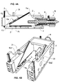
- FIG. 4A is a more detailed side view of the enlarged illustrated powertrain angulation of a third embodiment of the inventive powder press shown.
- the first driveline section 11 extending from the engine unit 10 to the angled region 11a, 12a is shown.
- a motor unit 10 in the form of a hollow shaft electric motor has a rotor 10a and a stator 10b.
- the rotor 10a is rotatably connected to a spindle 8 or formed integrally therewith.
- the stator 10b is rigidly connected to the frame 2 of the press (not shown).
- the spindle 8 is threadedly engaged with a nut 9.
- the nut 9 is rigidly connected to the first driveline section 11.
- the first drive train section 11 is linearly displaceable via a form-fitting guide F1 along the first action straight line L1.
- the second drive train section of which only its second end section 12a is shown, is linearly displaceable via a form-fitting guide F2 along the second action straight line L2.
- the first end section 11a of the first drive train section 11 is operatively connected to the second end section 12a of the second drive train section 12 (only partially shown) along a third action straight line L3 via a form-fitting guide F3.
- the third line of action L3 runs from bottom left to top right along a direction within the 90 ° angle range, which is spanned by the right-pointing effective straight line L1 and the upward-pointing effective straight line L2.
- the first driveline portion 11 is moved with its first end portion 11a to the left or to the right depending on the rotational direction of the rotor 10a.
- the second driveline portion 12 (only partially shown) is moved up and down with its second end portion 12a.
- the inclined surfaces of the first end portion are always constantly aligned along the third straight line of action L3 11a and the second end portion 12a in the horizontal and vertical directions, respectively.
- the angled drive train 11-12 operates as a force transducer and path converter, the ratio of the forces transmitted in the first driveline section 11 and the second driveline section 12 (thrust forces or tractive forces) is inverse to the ratio of that in the first driveline section 11 and the second drive train section 12 prevailing forces each other.
- a pin 21 is provided as a link between the inner section 12 'and the outer section 12'''.
- the connection of the two sections 12 'and 12'' is in the form of a screwed pin 21 which is in a region between the inner section
- the lower end and the upper end of the pin 21 are fixed to the inner portion 12 'and to the outer portion 12 "by screwing.
- the pin 21 allows on the one hand a transmission of compressive forces between the two sections 12 'and 12 "of the second drive train section 12 during a compression stroke and on the other hand, a transmission of tensile forces between the two sections 12' and 12" of the second drive train section 12 during a Expansionsshubs.
- the pin 21 is sufficiently flexible to allow in any direction transverse to the press axis (lifting axis) a relative displacement between the two sections 12 'and 12 "of the second drive train section 12.
- Fig. 4B is a perspective view of the enlarged illustrated powertrain angulation of a fourth embodiment of the inventive powder press shown.
- these end portions 11a and 12a are each formed yoke-shaped.
- the first end portion 11 a has a left yoke member 11 a1 and a right yoke member 11 a2, the two flat inclined surfaces lie in a common plane, the contiguous plane inclined surface of the first end portion 11 a of Fig. 4A equivalent.
- the first end portion 12a has a left yoke member 11a1 and a right yoke member 11a2, the two flat inclined surfaces lie in a common plane, the contiguous plane inclined surface of the second end portion 12a of Fig. 4A equivalent.
- the third embodiment of Fig. 4A and the fourth embodiment of Fig. 4B identical to the corresponding identical reference numerals in FIG FIGS. 4A and 4B ,
- the fourth embodiment has the further important advantage that the free space between the two abutting left yoke members 11a1 and 12a1 and the two adjacent right yoke members 11a2 and 12a2 can be used elsewhere.
- the bending range 11a, 12a with the power transmission through the two Jochglieder 11 a1, 12a1 left and the two yoke members 11 a2, 12a2 right another bending range 11a ', 12a' (see. Fig. 3 ) are provided, which is equipped with oppositely inclined flat inclined surfaces. This allows the introduction of diametrically opposite forces in the drive train.
- a powder press equipped with such a double bend or drive train branch contains two motor units 10, 10 ', which are in operative connection with the punch arrangement 13 and / or with the die arrangement 14 via a respective drive train 11-12, 11'-12.
- a right side drive train 11-12 extends from the right side motor unit 10 to the punch assembly 13 and / or to the die assembly 14, and a left side drive train 11'-12 extends from the left side motor unit 10 'to the punch assembly 13 and / or to the Die assembly 14 (see. Fig. 3 ).
- a first pin 21 and a second pin 22 are respectively provided as a connecting member between the inner section 12 'and the outer section 12 ", thus connecting two sections 12' and 12" in the form of two threaded pins 21 and 22, which are disposed in a region between the inner portion 12 'and the outer portion 12''.
- the lower end and the upper end of the respective pins 21 and 22 are on the inner portion 12' and on the outer portion 12, respectively "fastened by screwing.
- the two pins 21 and 22 allow on the one hand a transmission of compressive forces between the two sections 12 'and 12 "of the second drive train section 12 during a compression stroke and on the other hand, a transmission of tensile forces between the two sections 12' and 12" of the second drive train section 12 during an expansion stroke.
- the two pins 21 are sufficiently flexible to allow in any direction transverse to the press axis (lifting axis) a relative displacement between the two sections 12 'and 12 "of the second drive train section 12.
Landscapes
- Engineering & Computer Science (AREA)
- Mechanical Engineering (AREA)
- Press Drives And Press Lines (AREA)
Priority Applications (2)
| Application Number | Priority Date | Filing Date | Title |
|---|---|---|---|
| EP11175810A EP2551097A1 (fr) | 2011-07-28 | 2011-07-28 | Presse à poudre |
| PCT/EP2012/064520 WO2013014166A1 (fr) | 2011-07-28 | 2012-07-24 | Presse à poudre |
Applications Claiming Priority (1)
| Application Number | Priority Date | Filing Date | Title |
|---|---|---|---|
| EP11175810A EP2551097A1 (fr) | 2011-07-28 | 2011-07-28 | Presse à poudre |
Publications (1)
| Publication Number | Publication Date |
|---|---|
| EP2551097A1 true EP2551097A1 (fr) | 2013-01-30 |
Family
ID=46548501
Family Applications (1)
| Application Number | Title | Priority Date | Filing Date |
|---|---|---|---|
| EP11175810A Withdrawn EP2551097A1 (fr) | 2011-07-28 | 2011-07-28 | Presse à poudre |
Country Status (2)
| Country | Link |
|---|---|
| EP (1) | EP2551097A1 (fr) |
| WO (1) | WO2013014166A1 (fr) |
Families Citing this family (1)
| Publication number | Priority date | Publication date | Assignee | Title |
|---|---|---|---|---|
| JP5534122B1 (ja) | 2014-02-04 | 2014-06-25 | 千住金属工業株式会社 | 核ボール、はんだペースト、フォームはんだ、フラックスコート核ボールおよびはんだ継手 |
Citations (5)
| Publication number | Priority date | Publication date | Assignee | Title |
|---|---|---|---|---|
| DE2100505A1 (de) * | 1970-05-13 | 1971-11-18 | Kawaguchi, Ltd., Shimizu, Shizuoka (Japan) | Formpresse |
| GB1430921A (en) * | 1973-01-31 | 1976-04-07 | Braeuer W | Press for hot and cold working |
| US4535689A (en) * | 1982-08-25 | 1985-08-20 | Putkowski Ladislao W | Press with wedge |
| WO2009039895A1 (fr) * | 2007-09-24 | 2009-04-02 | Harald Weigelt | Transmission par clavettes avec logement d'élément de translation |
| EP2103423A1 (fr) * | 2008-03-17 | 2009-09-23 | Osterwalder AG | Presse à poudre destinée à la fabrication d'une pièce pressée en poudre de métal |
Family Cites Families (1)
| Publication number | Priority date | Publication date | Assignee | Title |
|---|---|---|---|---|
| DE102006012917B4 (de) * | 2006-03-13 | 2009-03-19 | Fraunhofer-Gesellschaft zur Förderung der angewandten Forschung e.V. | Element zur Übertragung von Kräften |
-
2011
- 2011-07-28 EP EP11175810A patent/EP2551097A1/fr not_active Withdrawn
-
2012
- 2012-07-24 WO PCT/EP2012/064520 patent/WO2013014166A1/fr not_active Ceased
Patent Citations (5)
| Publication number | Priority date | Publication date | Assignee | Title |
|---|---|---|---|---|
| DE2100505A1 (de) * | 1970-05-13 | 1971-11-18 | Kawaguchi, Ltd., Shimizu, Shizuoka (Japan) | Formpresse |
| GB1430921A (en) * | 1973-01-31 | 1976-04-07 | Braeuer W | Press for hot and cold working |
| US4535689A (en) * | 1982-08-25 | 1985-08-20 | Putkowski Ladislao W | Press with wedge |
| WO2009039895A1 (fr) * | 2007-09-24 | 2009-04-02 | Harald Weigelt | Transmission par clavettes avec logement d'élément de translation |
| EP2103423A1 (fr) * | 2008-03-17 | 2009-09-23 | Osterwalder AG | Presse à poudre destinée à la fabrication d'une pièce pressée en poudre de métal |
Also Published As
| Publication number | Publication date |
|---|---|
| WO2013014166A1 (fr) | 2013-01-31 |
Similar Documents
| Publication | Publication Date | Title |
|---|---|---|
| EP3707330A1 (fr) | Armature d'ouvrant pour un meuble, paroi latérale d'un corps de meuble et meuble doté d'une paroi latérale | |
| EP2855137B1 (fr) | Presse | |
| DE1452750A1 (de) | Verfahren und Vorrichtung zum Verbinden zweier Raender mindestens einer duennen Platte | |
| WO2020035364A1 (fr) | Colonne de direction pour véhicule automobile | |
| DE202010003706U1 (de) | Vorrichtung mit mindestens zwei relativ zueinander bewegbaren Teilen | |
| DE102008032750A1 (de) | Beschlag für kraftbetätigte Parallelausstellfenster | |
| DE102013012085B4 (de) | Presse zur Herstellung eines Presslings aus pulverförmigem Material | |
| DE102009055739B4 (de) | Umformmaschine, insbesondere Servopresse | |
| EP2551097A1 (fr) | Presse à poudre | |
| AT404811B (de) | Doppelkniehebelmechanismus zum bewegen der bewegbaren formaufspannplatte einer spritzgiessmaschine | |
| DE10241107A1 (de) | Pressmaschine | |
| DE2940517A1 (de) | Paletteneinpassmechanismus | |
| DE102016209427B3 (de) | Kupplungsaktuator | |
| DE102006046143B4 (de) | Kombinierte Zeitsteuerungs- und Verkettungsbaueinheit für eine Fertigholzproduktpresse | |
| DE102005062999B4 (de) | Elektromotorischer Möbelantrieb | |
| DE10241106B4 (de) | Pressmaschine | |
| DD268195A1 (de) | Presse | |
| EP2738333A2 (fr) | Ferme-porte | |
| DE102016209431B3 (de) | Kupplungsaktuator | |
| DE102010020729A1 (de) | Kraftübersetzer | |
| EP2498969A1 (fr) | Dispositif de serrage de buse d'une machine de moulage par injection | |
| DE19649063A1 (de) | Presse, insbesondere Schneid- und Umformpresse | |
| EP3512695B1 (fr) | Transmission par courroie trapézoïdale et procédé de production d'une transmission par courroie trapézoïdale à guidage optimisé | |
| EP0922827A1 (fr) | Crémone avec tringles à déplacement opposé et boítier excentrique | |
| DE10394176T5 (de) | Ausgeglichener Axoidkraftmechanismus und Axoidpresse |
Legal Events
| Date | Code | Title | Description |
|---|---|---|---|
| PUAI | Public reference made under article 153(3) epc to a published international application that has entered the european phase |
Free format text: ORIGINAL CODE: 0009012 |
|
| AK | Designated contracting states |
Kind code of ref document: A1 Designated state(s): AL AT BE BG CH CY CZ DE DK EE ES FI FR GB GR HR HU IE IS IT LI LT LU LV MC MK MT NL NO PL PT RO RS SE SI SK SM TR |
|
| AX | Request for extension of the european patent |
Extension state: BA ME |
|
| STAA | Information on the status of an ep patent application or granted ep patent |
Free format text: STATUS: THE APPLICATION HAS BEEN WITHDRAWN |
|
| 18W | Application withdrawn |
Effective date: 20130627 |