EP2551150B2 - Ensembles de sièges de sécurité pour enfants comportant des systèmes d'ancrage - Google Patents
Ensembles de sièges de sécurité pour enfants comportant des systèmes d'ancrage Download PDFInfo
- Publication number
- EP2551150B2 EP2551150B2 EP12178313.8A EP12178313A EP2551150B2 EP 2551150 B2 EP2551150 B2 EP 2551150B2 EP 12178313 A EP12178313 A EP 12178313A EP 2551150 B2 EP2551150 B2 EP 2551150B2
- Authority
- EP
- European Patent Office
- Prior art keywords
- base
- latches
- connector arms
- child safety
- safety seat
- Prior art date
- Legal status (The legal status is an assumption and is not a legal conclusion. Google has not performed a legal analysis and makes no representation as to the accuracy of the status listed.)
- Active
Links
Images


Classifications
-
- B—PERFORMING OPERATIONS; TRANSPORTING
- B60—VEHICLES IN GENERAL
- B60N—SEATS SPECIALLY ADAPTED FOR VEHICLES; VEHICLE PASSENGER ACCOMMODATION NOT OTHERWISE PROVIDED FOR
- B60N2/00—Seats specially adapted for vehicles; Arrangement or mounting of seats in vehicles
- B60N2/24—Seats specially adapted for vehicles; Arrangement or mounting of seats in vehicles for particular purposes or particular vehicles
- B60N2/26—Seats specially adapted for vehicles; Arrangement or mounting of seats in vehicles for particular purposes or particular vehicles for children
- B60N2/28—Seats readily mountable on, and dismountable from, existing seats or other parts of the vehicle
- B60N2/2803—Adaptations for seat belts
- B60N2/2806—Adaptations for seat belts for securing the child seat to the vehicle
-
- B—PERFORMING OPERATIONS; TRANSPORTING
- B60—VEHICLES IN GENERAL
- B60N—SEATS SPECIALLY ADAPTED FOR VEHICLES; VEHICLE PASSENGER ACCOMMODATION NOT OTHERWISE PROVIDED FOR
- B60N2/00—Seats specially adapted for vehicles; Arrangement or mounting of seats in vehicles
- B60N2/24—Seats specially adapted for vehicles; Arrangement or mounting of seats in vehicles for particular purposes or particular vehicles
- B60N2/26—Seats specially adapted for vehicles; Arrangement or mounting of seats in vehicles for particular purposes or particular vehicles for children
- B60N2/28—Seats readily mountable on, and dismountable from, existing seats or other parts of the vehicle
- B60N2/2821—Seats readily mountable on, and dismountable from, existing seats or other parts of the vehicle having a seat and a base part
- B60N2/2824—Seats readily mountable on, and dismountable from, existing seats or other parts of the vehicle having a seat and a base part part of the base being supported by the vehicle frame
-
- B—PERFORMING OPERATIONS; TRANSPORTING
- B60—VEHICLES IN GENERAL
- B60N—SEATS SPECIALLY ADAPTED FOR VEHICLES; VEHICLE PASSENGER ACCOMMODATION NOT OTHERWISE PROVIDED FOR
- B60N2/00—Seats specially adapted for vehicles; Arrangement or mounting of seats in vehicles
- B60N2/24—Seats specially adapted for vehicles; Arrangement or mounting of seats in vehicles for particular purposes or particular vehicles
- B60N2/26—Seats specially adapted for vehicles; Arrangement or mounting of seats in vehicles for particular purposes or particular vehicles for children
- B60N2/28—Seats readily mountable on, and dismountable from, existing seats or other parts of the vehicle
- B60N2/2821—Seats readily mountable on, and dismountable from, existing seats or other parts of the vehicle having a seat and a base part
- B60N2/2827—Seats readily mountable on, and dismountable from, existing seats or other parts of the vehicle having a seat and a base part part of the base being supported by the seat sub-frame
-
- B—PERFORMING OPERATIONS; TRANSPORTING
- B60—VEHICLES IN GENERAL
- B60N—SEATS SPECIALLY ADAPTED FOR VEHICLES; VEHICLE PASSENGER ACCOMMODATION NOT OTHERWISE PROVIDED FOR
- B60N2/00—Seats specially adapted for vehicles; Arrangement or mounting of seats in vehicles
- B60N2/24—Seats specially adapted for vehicles; Arrangement or mounting of seats in vehicles for particular purposes or particular vehicles
- B60N2/26—Seats specially adapted for vehicles; Arrangement or mounting of seats in vehicles for particular purposes or particular vehicles for children
- B60N2/28—Seats readily mountable on, and dismountable from, existing seats or other parts of the vehicle
- B60N2/2857—Seats readily mountable on, and dismountable from, existing seats or other parts of the vehicle characterised by the peculiar orientation of the child
- B60N2/286—Seats readily mountable on, and dismountable from, existing seats or other parts of the vehicle characterised by the peculiar orientation of the child forward facing
-
- B—PERFORMING OPERATIONS; TRANSPORTING
- B60—VEHICLES IN GENERAL
- B60N—SEATS SPECIALLY ADAPTED FOR VEHICLES; VEHICLE PASSENGER ACCOMMODATION NOT OTHERWISE PROVIDED FOR
- B60N2/00—Seats specially adapted for vehicles; Arrangement or mounting of seats in vehicles
- B60N2/24—Seats specially adapted for vehicles; Arrangement or mounting of seats in vehicles for particular purposes or particular vehicles
- B60N2/26—Seats specially adapted for vehicles; Arrangement or mounting of seats in vehicles for particular purposes or particular vehicles for children
- B60N2/28—Seats readily mountable on, and dismountable from, existing seats or other parts of the vehicle
- B60N2/2857—Seats readily mountable on, and dismountable from, existing seats or other parts of the vehicle characterised by the peculiar orientation of the child
- B60N2/2863—Seats readily mountable on, and dismountable from, existing seats or other parts of the vehicle characterised by the peculiar orientation of the child backward facing
-
- B—PERFORMING OPERATIONS; TRANSPORTING
- B60—VEHICLES IN GENERAL
- B60N—SEATS SPECIALLY ADAPTED FOR VEHICLES; VEHICLE PASSENGER ACCOMMODATION NOT OTHERWISE PROVIDED FOR
- B60N2/00—Seats specially adapted for vehicles; Arrangement or mounting of seats in vehicles
- B60N2/24—Seats specially adapted for vehicles; Arrangement or mounting of seats in vehicles for particular purposes or particular vehicles
- B60N2/26—Seats specially adapted for vehicles; Arrangement or mounting of seats in vehicles for particular purposes or particular vehicles for children
- B60N2/28—Seats readily mountable on, and dismountable from, existing seats or other parts of the vehicle
- B60N2/2875—Seats readily mountable on, and dismountable from, existing seats or other parts of the vehicle inclinable, as a whole or partially
-
- B—PERFORMING OPERATIONS; TRANSPORTING
- B60—VEHICLES IN GENERAL
- B60N—SEATS SPECIALLY ADAPTED FOR VEHICLES; VEHICLE PASSENGER ACCOMMODATION NOT OTHERWISE PROVIDED FOR
- B60N2/00—Seats specially adapted for vehicles; Arrangement or mounting of seats in vehicles
- B60N2/24—Seats specially adapted for vehicles; Arrangement or mounting of seats in vehicles for particular purposes or particular vehicles
- B60N2/26—Seats specially adapted for vehicles; Arrangement or mounting of seats in vehicles for particular purposes or particular vehicles for children
- B60N2/28—Seats readily mountable on, and dismountable from, existing seats or other parts of the vehicle
- B60N2/2887—Fixation to a transversal anchorage bar, e.g. isofix
- B60N2/289—Fixation to a transversal anchorage bar, e.g. isofix coupled to the vehicle frame
-
- B—PERFORMING OPERATIONS; TRANSPORTING
- B60—VEHICLES IN GENERAL
- B60N—SEATS SPECIALLY ADAPTED FOR VEHICLES; VEHICLE PASSENGER ACCOMMODATION NOT OTHERWISE PROVIDED FOR
- B60N2/00—Seats specially adapted for vehicles; Arrangement or mounting of seats in vehicles
- B60N2/24—Seats specially adapted for vehicles; Arrangement or mounting of seats in vehicles for particular purposes or particular vehicles
- B60N2/26—Seats specially adapted for vehicles; Arrangement or mounting of seats in vehicles for particular purposes or particular vehicles for children
- B60N2/28—Seats readily mountable on, and dismountable from, existing seats or other parts of the vehicle
- B60N2/2887—Fixation to a transversal anchorage bar, e.g. isofix
- B60N2/2893—Fixation to a transversal anchorage bar, e.g. isofix coupled to the seat sub-frame
Definitions
- the present inventions relate to child safety seat assemblies having anchor systems.
- WO 2008/059036 A1 and EP 1600325 A2 are disclosing child safety seat assembly comprising: a base two connector arms assembled with the base.
- the connector arms being provided with locking fasteners operable to engage with an anchorage bracket in a vehicle to lock the base in place.
- the connector arms are movable relative to the base to adjust a length of extension of the connector arms outside the base.
- one latch assembled with the base and operable to lock the connector arms in position with the base wherein one release actuator is disposed in a region of the base between the connector arms and operatively connected with the latch, wherein the release actuator is operable to drive an unlocking displacement of the latch. Due to the central release actuator a complex assembly is necessary for operating in relation to the length adjustment
- the object of the invention is to provide a child safety scat assembly that has an adjustable anchor system providing a length adjustment assuring a save anchoring by simple means. This object is solved by the features of claim 1.
- the present application describes child safety seat assemblies having adjustable anchor systems used for installation in a vehicle.
- the child safety seat assembly comprises a base, two connector arms assembled with the base, two latches assembled with the base and operable to respectively lock the two connector arms in position with the base, and two release actuators disposed in a region of the base between the connector arms, formed as integral handles, and respectively connected with the two latches.
- the connector arms are provided with locking fasteners operable to engage with an anchorage bracket in a vehicle to lock the base in place, the connector arms being movable relative to the base to adjust a length of extension of the connector arms outside the base.
- the two release actuators are operable to drive unlocking displacements of the two latches and are movable transversally relative to the base to drive displacements of the latches in opposite directions.
- Each of the latches has an elongated shape that extends transversally relative to the base and is assembled through a slot of the associated release actuators with an end respectively affixed with the two release actuators via a pin, wherein the slot extends parallel to an axis of displacement of the respective release actuator.
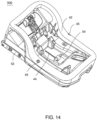
- a child safety seat assembly can include a base 210 provided with an anchor structure 220 and an adjustment mechanism 100.
- the base 210 can be adapted to removably attach with a child seat.
- the anchor structure 220 can include two elongated connector arms 221 and 222 that are assembled at left and right sides of the base 210. For adjusting a length of extension of the connector arms 221 and 222 outside the base 210, the connector arms 221 and 222 can be movable back and forth to extend from and retract into the base 210.
- the adjustment mechanism 100 can include a release actuating assembly 30, and latches 10 and 20.
- the latches 10 and 20 can be assembled with the base 210, and are operable to lock the connector arms 221 and 222 with the base 210.
- the release actuating assembly 30 is disposed between the two connector arms 221 and 222, and includes two release actuators 31 and 32 respectively connected with the latches 10 and 20.
- the release actuator 31 can be connected with an end of the latch 10, which can extend along a transversal direction and have another opposite end capable of engaging with the connector arm 221.
- the release actuator 32 can be connected with an end of the latch 20, which can also extend along the transversal direction and have an opposite end capable of engaging with the connector arm 222.
- the release actuators 31 and 32 can be operable to drive the latches 10 and 20 to move in opposite directions transversally relative to the base 210 and the connector arms 221 and 222.
- the latches 10 and 20 can be operable to engage and lock the connector arms 221 and 222 in place, and disengage and unlock from the connector arms 221 and 222 to allow adjustment of the connector arms 221 and 222 relative to the base 210.
- the base 210 can include a lower shell body 210a and an upper shell body 210b.
- the lower shell body 210a and the upper shell body 210b can be fixedly assembled together via fastener screws to define a housing shell through which the connector arms 221 and 222 and the adjustment mechanism 100 can be movably assembled.
- the connector arms 221 and 222 can have end portions provided with locking fasteners 225 operable to attach with an anchorage bracket provided in a vehicle to lock the base 210 in place.
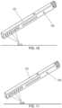
- the latch 10 has an elongated shape extending transversally relative to the base 210, and with an end affixed with the release actuator 31.
- the release actuator 31 is formed as an integral handle, and the latch 10 can be affixed with the release actuator 31 via a pin 34.
- This assembly is simple to realize and reliable in construction.
- the release actuator 31 includes a slot 31b that extends parallel to an axis of displacement of the release actuator 31, and can include a cavity 31c that extends parallel to an axis of displacement of the connector arm 221 and communicates with the slot 31b.
- the cavity 31c can have two opposite inner sidewalls from which claws 31d protrude toward the slot 31b.
- the latch 10 can be inserted through the slot 31b, and the pin 34 can be disposed in the cavity 31c and insert through the latch 10.
- the claw 31d can be disposed so as to abut against the pin 34, whereby movement of the pin 34 along the cavity 31c can be blocked to prevent detachment of the pin 34 from the latch 10 during operation.
- the pin 34 can be thereby securely held with the latch 10.
- the latch 10 can have another end portion that can move parallel to the axis of displacement of the release actuator 31 to operatively engage and disengage the connector arm 221.
- the latch 20 can be assembled in a similar manner. More specifically, the latch 20 has an elongated shape extending transversally relative to the base 210, and with an end affixed with the release actuator 32 via a pin 35.
- the release actuator 32 includes a slot 32b that extends parallel to an axis of displacement of the release actuator 32, and can include a cavity 32c that extends parallel to an axis of displacement of the connector arm 222 and communicates with the slot 32b.
- the cavity 32c can have two opposite inner sidewalls from which claws 32d protrude toward the slot 32b.
- the latch 20 can be inserted through the slot 32b, and the pin 35 can be disposed in the cavity 32c and insert through the latch 20.
- the claw 32d can be disposed so as to abut against the pin 35, whereby movement of the pin 35 along the cavity 32c can be blocked to prevent detachment of the pin 35 from the latch 20 during operation.
- the pin 35 can be thereby securely held with the latch 20.
- the latch 20 can have another end portion that can move parallel to the axis of displacement of the release actuator 32 to operatively engage and disengage the connector arm 222.
- the latches 10 and 20 can be concurrently driven in movement to unlock from the connector arms 221 and 222, respectively.
- the release actuators 31 and 32 can be disposed in alignment with a common transversal axis of the base 210. Moreover, middle areas of the release actuators 31 and 32 can be respectively provided with recessed cavities 31a and 32a to facilitate placement of the caregiver's fingers for operating the release actuators 31 and 32.
- the release actuators 31 and 32 can recover initial positions corresponding to the locking state of the latches 10 and 20 by a spring force.
- the release actuating assembly 30 can also include a spring 33 disposed between the release actuators 31 and 32.
- the spring 33 can have two opposite ends respectively mounted around studs 31e and 32e protruding toward each other from two mutually facing sidewalls of the release actuators 31 and 32.
- the spring 33 is operable to bias the release actuators 31 and 32 and the latches 10 and 20 toward a locking state.
- the connector arm 221 can include a row of locking openings 221a through any of which the latch 10 can engage to lock the connector arms 221 and 222 in position.
- the connector arm 222 can include a row of locking openings 222a through any of which the latch 20 can engage to lock the connector arms 221 and 222 in position. Adjacent locking openings 221a on the connector arm 221 (and locking openings 222a on the connector arm 222) can be spaced apart from each other by a same or varying interval.
- the anchor structure 220 can include a transversal bar linkage 223 having two opposite ends respectively affixed with the connector arms 221 and 222.
- the bar linkage 223 can fixedly engage through mount holes 226 provided in the connector arms 221 and 222.
- the arrangement of the bar linkage 223 can allow to concurrently drive the connector arms 221 and 222 during rearward and forward adjustment.
- the bar linkage 223 can also form an abuttal structure capable of preventing excessive displacements of the connector arms 221 and 222 that may result in their disassembling from the base 210.
- the release actuators 31 and 32 can be manually operated to move transversally toward each other. Driven by the release actuators 31 and 32, the latches 10 and 20 can move toward each other to compress the spring 33 and disengage and unlock from the connector arms 221 and 222. Being unlocked, the connector arms 221 and 222 can be displaced forward relative to the base 210, the latches 10 and 20 and the release actuators 31 and 32 to retract toward the interior of the base 210. Once the connector arms 221 and 222 reach the retracted state as shown in Figure 3 , the release actuators 31 and 32 can be released.
- the spring 33 can drive the release actuators 31 and 32 and the associated latches 10 and 20 to move transversally away from each other until the latches 10 and 20 respectively engage and lock with the connector arms 221 and 222.
- the connector arms 221 and 222 can be thereby held in the retracted state.
- the latches 10 and 20 can be switched to the unlocked state like described previously.
- the connector arms 221 and 222 then can be moved rearward relative to the base 210, the latches 10 and 20 and the release actuators 31 and 32 to extend outward.
- alternate embodiments of the release actuating assembly 30 may also include two spring members respectively connected with the latches 10 and 20.
- the two spring members can bias the latches 10 and 20 to engage and lock with the connector arms 221 and 222 in place.
- the two spring members can be displaced transversally toward each other so that the latches 10 and 20 can concurrently move toward each other to disengage and unlock from the connector arms 221 and 222.
- the spring members can urge the latches 10 and 20 to engage and lock with the connector arms 221 and 222, which can be thereby held in position.
- the connector arms 221 and 222 can be desirably adjusted to extend outside the base 210 for attachment with a vehicle anchorage, or retracted to be substantially concealed in the base 210. Concealment of the connector arms 221 and 222 in the base 210 can facilitate storage and shipment of the base 210, and prevent inadvertent injuries caused by the exposure of sharp edges of the connector arms 221 and 222.
- alternate embodiments may also implement a simplified construction using one latch 10 or 20 associated with one release actuator 31 or 32. Since the two connector arms 221 and 222 are connected via the transversal bar linkage 223, this simplified construction may also work to lock the connector arms 221 and 222 in place.
- Figures 12-21 are schematic views illustrating another embodiment of a child safety seat assembly 400 that can include a seat shell 41, a base 42 and a retractable anchor structure 500.
- the seat shell 41 can be removably installed on the base 42.
- the anchor structure 500 can be assembled with the base 42.
- the child safety seat assembly 400 can be securely attached with an anchorage fixture provided in a vehicle via the anchor structure 500.
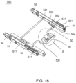
- the anchor structure 500 can include a support frame, connector arms 52, a transversal bar linkage 53 and a release actuator 54.
- the support frame can be fixedly secured inside the base 42.
- Each connector arm 52 can have a hollow structure.
- the connector arms 52 can be assembled with the support frame, and can be desirably adjusted to extend outward from the base 42 or retract toward an interior of the base 42.
- the bar linkage 53 can extend transversally, and can be connected with the connector arms 52.
- the support frame can include a locking structure disposed along an axis of displacement of the connector arms 52, and the bar linkage 53 can include latches 55 operable to engage with the locking structure.
- the release actuator 54 can be installed with the bar linkage 53, and can be operable to drive the latches 55 to engage or disengage the locking structure of the support frame.
- the support frame can include two fixed tube segments 51 that are affixed with the base 42 transversally spaced apart from each other. Reinforcing plates 513 and bars 514 extending transversally may also be affixed with the tube segments 51.
- Each tube segment 51 can include an inner cavity that extends lengthwise along the tube segment 51.
- the connector arms 52 can be assembled so as to be movable relative to the tube segments 51.
- the bar linkage 53 can have two opposite ends respectively assembled through the inner cavity of the tube segments 51 at a perpendicular angle to affix with one associated latch 55.
- the locking structure of the support frame can be formed as locking openings 511 distributed along an upper surface of each tube segment 51.
- the locking openings 511 should be at least 3 in number, and include 6 ones as shown in the illustrated embodiment.
- the two latches 55 can be respectively disposed in the tube segments 51.
- Each latch 55 can be formed in one integral piece including a hub portion 551 affixed with an end of the bar linkage 53, an extension 552 connected with the hub portion 551, and an engaging tip 553 projecting from the extension 552 toward the locking openings 511.
- the engaging tip 553 can have a protruding shape and size adapted to engage through any of the locking openings 511 to lock the connector arms 52 in position.
- the hub portion 551 can be disposed in the inner cavity of the tube segment 51, and can have a curved shape that can be wrapped by a protective sleeve 554.
- the extension 552 may also be pivotally connected with the hub portion 551, and the release actuator 54 can be directly connected with the extension 552. In this manner, the release actuator 54 can operatively control the rotation of the extension 552 to have the engaging tip 553 engage or disengage any of the locking openings 511.
- the two connector arms 52 can be respectively assembled with the tube segments 51.
- a transversal bar 521 can be connected with the two connector arms 52.
- the release actuator 54 can be placed at a middle region of the base 42 between the two connector arms 52, and can be operable to rotate relative to the connector arms 52 to drive displacement of the latches 55 between a locking state and an unlocking state.
- the bar linkage 53 can have two opposite ends pivotally connected with the two connector arms 52, and a middle bent portion 531 having a U-shape at which the release actuator 54 can be assembled with the bar linkage 53 eccentric from the pivot axis of the bar linkage 53 relative to the connector arms 52.
- the release actuator 54 can be formed as a handle to facilitate manual operation.
- the release actuator 54 can drive rotation of the bar linkage 53 (e.g., in an anti-clockwise direction in the figure) relative to the connector arms 52.
- the latches 55 can rotate with the bar linkage 53 to cause the engaging tips 553 to disengage from a pair of the locking openings 511, which unlocks the connector arms 52.
- the bar linkage 53 can be disposed in the base 42.
- the base 42 can include an elongated slot 44 that extends lengthwise parallel to the axis of movement of the connector arms 52.
- the release actuator 54 can include a handle 541 and a stem 542.
- the stem 542 can be assembled with the bar linkage 53, and pass through the elongated slot 44 to affix with the handle 541 which is exposed and accessible from the outside of the base 42.
- a spring 43 can be mounted around the stem 542, and have two ends connected with the bar linkage 53 and the base 42. The spring 43 can apply a drawing force that can pull the release actuator 54 downward to a locking state where the connector arms 52 are locked in place with the tube segments 51 via the latches 55.
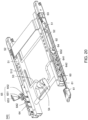
- the child safety seat assembly 400 can further include a driving mechanism 60 operable to actuate the locking fasteners 63.
- Each connector arm 52 can have an end mounted with a locking fastener 63.
- a construction of the locking fastener 63 may include a latching hook, and an actuating part operable to drive the hook to engage and disengage the anchorage bracket of the vehicle (not shown).
- the driving mechanism 60 can also include linking bars 63, and a fastener release actuator 61 operatively connected with the linking bars 63.
- Each linking bar 62 can be assembled through the interior of one associated connecting arm 52, and can connect with the latching hook of the fastener 63.
- the two linking bars 63 may be connected with each other via a transversal link so that the linking bars 63 can be driven in a concurrent manner.
- the fastener release actuator 61 can be movably assembled in the base 42, and can be accessible from the outside of the base 42. As shown in Figure 21 , a spring 611 can be assembled between the fastener release actuator 61 and the base 42.
- the spring 611 can apply a biasing force to the fastener release actuator 61 in a direction similar to that of the locking direction.
- the fastener release actuator 61 can drive the linking bars 62 in movement, which in turn can drive the actuating part of the fasteners 63 to concurrently turn the hooks to the unlocking state.
- the child safety seat assembly 400 can further include an indicator mechanism adapted to indicate a locking state of the child safety seat assembly 400.
- the indicator mechanism can include two assemblies of racks 64 and indicator actuating parts 65 respectively associated with the two connector arms 52.
- the racks 64 can be respectively disposed above the connector arms 52, and can be movable relative to the connector arms 52 within a limited range of displacement.
- Each connector arm 52 can include a guide slot 522 through which one rack 64 can be movably installed in engagement with the linking bar 62 located in the connector arm 52.
- An upper surface of the rack 64 can include a plurality of spaced-apart protrusions 641 distributed along the axis of movement of the connector arm 52. In one embodiment, the protrusions 641 can be disposed at intervals mapping with the preset intervals of the locking openings 511.
- the indicator actuating part 65 can include a shaft portion 651 pivotally connected with the base 42, a panel 653 fixedly connected with the shaft portion 651 and extending to a viewing window 45 formed through a sidewall of the base 42, and an extension 652 affixed with a side of the shaft portion 651 and lying in contact with the protrusions 641 of one associated rack 64.
- the panel 653 can have a plurality of indicator marks spaced apart from each other.
- the indicator marks may include texts, patterns, icons, regions of different colors, or the like. These indicator marks may be printed, painted, drawn, adhered or carved on the panel 653.
- the panel 653 may exemplary display two color regions, e.g., red and green regions.
- a spring (not shown) can be assembled between the indicator actuating part 65 and the base 42 so as to bias the extension 652 in contact against the protrusions 641.
- a side of the rack 64 can also include a plurality of fingers 642 configured to prevent detachment of the rack 64 from the connector arm 52.
- the release actuator 54 can be operated to unlock the connector arms 52.
- the connector arms 52 then can be driven in movement relative to the base 42, which also drive concurrent displacement of the racks 64.
- the protrusions 641 can successively hit the extension 652 so as to cause reciprocated rotational displacement of the panel 653 for indicating a current position of the connector arms 52 with respect to the locking openings 511.
- the panel 653 may display one color region at the viewing window 45 when the connector arms 52 are correctly aligned with preset locking positions corresponding to a pair of the locking openings 511, and another color region when the connector arms 52 are not aligned with any preset locking positions. In this manner, it can be ensured that the connector arms 52 are stopped at permitted positions where the latches 55 are properly aligned with one pair of corresponding locking openings 511 to effectuate locking.
- the fastener release actuator 61 can be pulled outward (e.g., toward the left side of the figure) to cause displacement of the linking bars 62, which in turn drive the actuating parts of the fasteners 63 to switch the fastener hooks from the locking state to the unlocking state.
- the movement of each linking bar 62 can also drive displacement of the associated rack 64 in the same direction relative to the connector arm 52, such that one adjacent protrusion 641 of the rack 64 can move away from the extension 652 of the indicator actuating part 65.
- the extension 652 and the panel 653 can accordingly rotate about the pivot axis of the shaft portion 651 (e.g., in the clockwise direction in the figure) until the red color region on the panel 653 can display at the viewing window 45 of the base 42 to indicate that the fasteners 63 are in the unlocking state.
- the spring 611 can drive the fastener release actuator 61 and the linking bars 62 to slide in a reverse direction (e.g., toward the right side of the figure), which in turn drive the actuating parts of the fasteners 63 to turn the fastener hooks to the locking state.
- the sliding movement of each linking bar 62 can also drive displacement of the associated rack 64 in the same direction relative to the connector arm 52.
- one protrusion 641 can push the extension 652 and the panel 653 to rotate reversely (e.g., in the anti-clockwise direction in the figure) about the pivot axis of the shaft portion 651, until the green color region on the panel 653 displays at the viewing window 45 to indicate that the fasteners 63 are in the locking state.
- driving mechanism 60 and the indicator mechanism have been described in association with the anchor structure 500, it will be appreciated that this does not limit its scope of application. Similar constructions of the driving mechanism 60 and the indicator mechanism can be implemented in association with any anchor structures, such as the anchor structure 220 described in conjunction with Figures 1-11 .
- the release actuator 54 can be rotated upward, which drives the bar linkage 53 and the latches 55 to rotate in a same direction to disengage the latches 55 from a pair of the locking openings 511.
- the connector arms 52 can be thereby unlocked for adjustment.
- the handle 541 then can be grasped and displaced along the elongated slot 44 to move the bar linkage 53 and the connector arms 52 back and forth as desired relative to the fixed tube segments 51 and the base 42.
- the latches 55 also move concurrently along the interior of the fixed tube segments 51. Once the connector arms 52 reach the desired position, the handle 541 can be released.
- the spring 43 can urge the release actuator 54 downward to recover an initial position, which drives the bar linkage 53 and the latches 55 to rotate reversely until the latches 55 engage with a pair of corresponding locking openings 511.
- the connector arms 52 can be thereby locked in position relative to the base 42.
Landscapes
- Engineering & Computer Science (AREA)
- Health & Medical Sciences (AREA)
- Child & Adolescent Psychology (AREA)
- General Health & Medical Sciences (AREA)
- Aviation & Aerospace Engineering (AREA)
- Transportation (AREA)
- Mechanical Engineering (AREA)
- Seats For Vehicles (AREA)
- Lock And Its Accessories (AREA)
Claims (7)
- Assemblage de siège de sécurité pour enfants comprenant :une base (210) ;deux bras connecteurs (221, 222) assembles avec la base (210), les bras connecteurs (221, 222) étant fournis avec des éléments de fixation à blocage (225) actionnables pour s'enclencher avec une patte d'ancrage dans un véhicule pour verrouiller en place la base (210), dans lequel les bras connecteurs (221, 222) sont déplaçables par rapport à la base (210) pour ajuster une longueur d'extension des bras connecteurs (221, 222) hors de la base; etdeux verrous (10, 20) assemblés avec la base (210) et actionnables pour, respectivement, verrouiller en place les deux bras connecteurs (221, 222) avec la base (210),l'assemblage de siège de sécurité pour enfants étant caractérisé en ce que :
deux actionneurs de déverrouillage (31, 32) formés comme des poignées intégrales sont disposés dans une région de la base (210) entre les bras connecteurs (221, 222) et sont respectivement connectés avec les deux verrous (10, 20) et actionnables pour entraîner des déplacements de déverrouillage des deux verrous (10, 20), les deux actionneurs de déverrouillage (31, 32) étant déplaçables transversalement par rapport à la base (210) pour entraîner des déplacements des verrous (10, 20) dans des directions opposées, dans lequel chacun des verrous (10, 20) présente une forme allongée qui s'étend transversalement par rapport à la base (210) et est assemblé à travers une fente (31b, 32b) de l'actionneur de déverrouillage (31, 32) associe avec une extrémité respectivement fixée aux deux actionneurs de déverrouillage (31, 32) par l'intermédiaire d'une goupille (34, 35), dans laquelle la fente (31b, 32b) s'étend parallèlement à un axe de déplacement de l'actionneur de déverrouillage respectif (31, 32). - Assemblage de siège de sécurité pour enfants selon la revendication 1, dans lequel les deux verrous (10, 20) sont déplaçables transversalement par rapport à la base (210), et les bras connecteurs (221, 222) sont déplaçables en avant et en arrière par rapport à la base (210) étaux verrous (10, 20), au moins l'un des bras connecteurs (221, 222) comportant une multitude d'ouvertures de verrouillage (221a, 222a) à travers l'une quelconque desquelles le verrou (10, 20) correspondant s'enclenche pour verrouiller en place les bras connecteurs (221, 222).
- Assemblage de siège de sécurité pour enfants selon la revendication 1, dans lequel les deux verrous (10, 20) sont respectivement connectés avec les deux actionneurs de déverrouillage (31, 32) et sont déplaçables transversalement par rapport à la base (210).
- Assemblage de siège de sécurité pour enfants selon l'une des revendications précédentes, dans lequel les deux actionneurs de déverrouillage (31, 32) sont connectés avec un ressort (33) actionnable pour incliner les actionneurs de déverrouillage (31, 32) et les verrous (10, 20) vers un état de verrouillage.
- Assemblage de siège de sécurité pour enfants selon la revendication 4, dans lequel le ressort (33) est assemblé entre les deux actionneurs de déverrouillage (31, 32), le ressort (33) étant actionnable pour incliner les actionneurs de déverrouillage (31, 32) et les verrous (10, 20) dans des directions opposées vers l'état de verrouillage.
- Assemblage de siège de sécurité pour enfants selon l'une des revendications précédentes, dans lequel les bras connecteurs (221, 222) sont connectés l'un avec l'autre via un couplage à barre transversale (223).
- Assemblage de siège de sécurité pour enfants selon l'une des revendications précédentes, dans lequel les deux actionneurs de déverrouillage (31, 32) sont respectivement connectés avec une extrémité des deux verrous (10, 20), les deux verrous (10, 20) s'étendant le long d'une direction transversale et comportant des extrémités opposées capables de s'engager avec les deux bras connecteurs (221, 222), respectivement, lesdites extrémités des deux verrous (10, 20) se déplaçant parallèlement à l'axe de déplacement des deux actionneurs de déverrouillage (31, 32) pour engager et désengager de manière opérationnelle les deux bras connecteurs (221, 222), respectivement.
Applications Claiming Priority (2)
| Application Number | Priority Date | Filing Date | Title |
|---|---|---|---|
| CN201110215384.5A CN102897062B (zh) | 2011-07-29 | 2011-07-29 | 伸缩式连接装置及儿童汽车座椅 |
| CN201110267291.7A CN102991381B (zh) | 2011-09-09 | 2011-09-09 | 儿童汽车座椅固定装置的调整机构及儿童汽车座椅 |
Publications (4)
| Publication Number | Publication Date |
|---|---|
| EP2551150A2 EP2551150A2 (fr) | 2013-01-30 |
| EP2551150A3 EP2551150A3 (fr) | 2014-06-18 |
| EP2551150B1 EP2551150B1 (fr) | 2016-12-14 |
| EP2551150B2 true EP2551150B2 (fr) | 2024-06-12 |
Family
ID=46639341
Family Applications (1)
| Application Number | Title | Priority Date | Filing Date |
|---|---|---|---|
| EP12178313.8A Active EP2551150B2 (fr) | 2011-07-29 | 2012-07-27 | Ensembles de sièges de sécurité pour enfants comportant des systèmes d'ancrage |
Country Status (3)
| Country | Link |
|---|---|
| US (1) | US9315123B2 (fr) |
| EP (1) | EP2551150B2 (fr) |
| DE (1) | DE202012013706U1 (fr) |
Families Citing this family (33)
| Publication number | Priority date | Publication date | Assignee | Title |
|---|---|---|---|---|
| CN103419687B (zh) * | 2012-05-15 | 2016-01-27 | 明门香港股份有限公司 | 儿童安全座椅的固定装置 |
| CN203752939U (zh) * | 2013-04-03 | 2014-08-06 | 中山市隆成日用制品有限公司 | 设有显示装置的儿童约束装备 |
| CN104290622B (zh) | 2013-07-19 | 2016-12-28 | 明门香港股份有限公司 | 安全座椅固定装置调整机构 |
| CN203713613U (zh) * | 2013-08-15 | 2014-07-16 | 中山市隆成日用制品有限公司 | 幼儿汽车安全座椅锁定的安全显示设备 |
| NO337587B1 (no) * | 2013-09-19 | 2016-05-09 | Torgersen Hans & Soenn | Barnesete |
| CN103496331B (zh) * | 2013-10-21 | 2016-01-27 | 宁波三泰儿童用品有限公司 | 一种可伸缩的汽车儿童安全座椅isofix装置 |
| CN104709126B (zh) * | 2015-02-12 | 2017-05-31 | 王建新 | 一种儿童安全座椅及安装方法 |
| MX2017013976A (es) * | 2015-05-12 | 2018-03-14 | Pidyon Controls Inc | Asiento para automovil y sistema de conexion. |
| WO2017186785A1 (fr) | 2016-04-29 | 2017-11-02 | Holmbergs Safety System Holding Ab | Barre de raccordement pour un système destiné à retenir un enfant |
| SE541694C2 (en) | 2017-03-22 | 2019-11-26 | Holmbergs Safety System Holding Ab | Adjustable connecting bar for a child restraint system |
| CN106926758B (zh) * | 2017-04-27 | 2023-08-22 | 长春富维安道拓汽车饰件系统有限公司 | 一种儿童座椅座盆底座连接系统 |
| CN207267463U (zh) * | 2017-07-13 | 2018-04-24 | 浙江感恩科技股份有限公司 | 一种儿童安全座椅的调节机构 |
| GB2565047B (en) | 2017-07-24 | 2023-01-25 | Scott Macliver Kevin | Child safety seat |
| CN109305074B (zh) * | 2017-07-26 | 2023-10-13 | 珠海阳光儿童用品有限公司 | Isofix伸缩调节装置及儿童安全座椅 |
| CN207257443U (zh) * | 2017-08-03 | 2018-04-20 | 宁波宝贝第一母婴用品有限公司 | 一种具有isofix止退结构的安全座椅 |
| US10906436B2 (en) * | 2018-02-21 | 2021-02-02 | Artsana Usa, Inc. | Quick release apparatus for a latch connector on a booster seat |
| US10821905B2 (en) * | 2018-03-12 | 2020-11-03 | Honda Motor Co., Ltd | Apparatus for attaching an accessory to a seat and methods of use thereof |
| US10737593B1 (en) | 2018-07-02 | 2020-08-11 | Summer Infant (Usa), Inc. | Car seat |
| CN208576461U (zh) * | 2018-07-17 | 2019-03-05 | 宁波宝贝第一母婴用品有限公司 | 一种isofix止退二道锁机构 |
| WO2020023609A1 (fr) | 2018-07-27 | 2020-01-30 | Safest Seats Llc | Plate-forme de support avec piétement de charge pour siège de voiture pour enfant |
| US11155187B2 (en) | 2018-09-12 | 2021-10-26 | Wonderland Switzerland Ag | Child restraint base and child restraint system |
| CN110901484B (zh) * | 2018-09-14 | 2023-02-21 | 明门瑞士股份有限公司 | 底座 |
| CN109017476A (zh) * | 2018-09-30 | 2018-12-18 | 重庆贝艾思汽车用品有限公司 | 可伸缩的儿童安全座椅isofix结构 |
| EP3689671B1 (fr) | 2019-01-30 | 2022-01-26 | Axkid AB | Ensemble de siège de sécurité pour enfants |
| CN110949205B (zh) * | 2019-12-09 | 2025-01-21 | 好孩子儿童用品有限公司 | 一种儿童安全座椅 |
| USD1074287S1 (en) * | 2020-09-17 | 2025-05-13 | Wonderland Switzerland Ag | Base for infant car seat |
| CN114368327B (zh) | 2020-10-14 | 2025-02-11 | 宝钜瑞士股份有限公司 | 伸缩调整结构 |
| CN119189817A (zh) * | 2020-12-11 | 2024-12-27 | 宝钜瑞士股份有限公司 | 儿童安全座椅及座椅底座 |
| CN114906024B (zh) * | 2021-02-08 | 2024-07-30 | 宝钜瑞士股份有限公司 | 固定装置、底座装置及承载装置 |
| US20220295739A1 (en) * | 2021-03-19 | 2022-09-22 | Sure Loc Pet Carriers LLC | Pet carrier |
| CN115675204A (zh) * | 2021-07-21 | 2023-02-03 | 明门瑞士股份有限公司 | 具有滑动机构改良的婴幼童载具 |
| SE546227C2 (en) | 2022-06-03 | 2024-07-16 | Holmbergs Safety System Holding Ab | Adjustable connecting bar for child safety seat in vehicle, adjustable mounting arrangement, and child safety seat |
| CN115891785A (zh) * | 2022-11-24 | 2023-04-04 | 珠海阳光儿童用品有限公司 | 一种具有可换向连接的isofix连接器的儿童安全座椅 |
Citations (2)
| Publication number | Priority date | Publication date | Assignee | Title |
|---|---|---|---|---|
| CN201677768U (zh) † | 2010-05-13 | 2010-12-22 | 麦克英孚(宁波)婴童用品有限公司 | 一种具有底座平移结构的汽车用儿童座椅 |
| CN201777158U (zh) † | 2010-03-15 | 2011-03-30 | 麦克英孚(宁波)婴童用品有限公司 | 一种用于儿童安全支撑物的基座 |
Family Cites Families (31)
| Publication number | Priority date | Publication date | Assignee | Title |
|---|---|---|---|---|
| GB9320169D0 (en) * | 1993-09-30 | 1993-11-17 | Britax Excelsior | Child safety seat |
| AUPN649595A0 (en) * | 1995-11-10 | 1995-12-07 | Britax Child-Care Products Pty Ltd | Reclining mechanism and latch for child safety seat |
| JP3620174B2 (ja) * | 1996-10-17 | 2005-02-16 | タカタ株式会社 | チャイルドシート |
| GB9808785D0 (en) * | 1998-04-25 | 1998-06-24 | Britax Excelsior | Child safety seat |
| US6962394B2 (en) * | 1998-08-18 | 2005-11-08 | Indiana Mills & Manufacturing, Inc. | Restraint coupling |
| JP3656512B2 (ja) * | 1999-05-10 | 2005-06-08 | タカタ株式会社 | チャイルドシート |
| NL1015020C2 (nl) * | 2000-04-26 | 2001-10-30 | Maxi Miliaan Bv | Bevestigingselement voor het losneembaar bevestigen van een stoeldrager aan een voertuigstoel alsmede dergelijke stoeldragers. |
| DE10207581A1 (de) | 2002-02-22 | 2003-09-11 | Opel Adam Ag | Kindersitz mit drehbaren Transpondern |
| ES2196999A1 (es) * | 2002-03-14 | 2003-12-16 | Play Sa | Silla infantil para automoviles. |
| NL1020764C2 (nl) * | 2002-06-05 | 2003-12-08 | Maxi Miliaan Bv | Kindervoertuigstoel voorzien van een onderstel en een met het onderstel verbonden stoel alsmede een dergelijk onderstel. |
| GB2412577B (en) * | 2004-03-31 | 2008-02-20 | Catalyst Developments | Fitting for child safety seat |
| ITTO20040322A1 (it) | 2004-05-14 | 2004-08-14 | Belt & Buckle Srl | Sistema di accoppiamento per accoppiare in modo scorrevole a scatti due elementi di un sistema di ancoraggio di un seggiolino per bambini ad un sedile di autoveicolo |
| US7384099B2 (en) * | 2004-11-18 | 2008-06-10 | Ford Global Technologies, Llc | Apparatus and a method for assessing an anchorage position |
| NL1028788C2 (nl) * | 2005-04-18 | 2006-10-20 | Maxi Miliaan Bv | Onderstel alsmede kindervoertuigstoel voorzien van een dergelijk onderstel. |
| FR2889826B1 (fr) * | 2005-08-17 | 2008-10-17 | Equipbaby Uk Ltd | Siege de securite destine a installer un bebe ou un tres jeune enfant sur un siege de vehicule. |
| DE102006011520B4 (de) | 2006-03-10 | 2011-05-05 | Recaro Gmbh & Co. Kg | Kindersitz |
| ES1063434Y (es) * | 2006-07-14 | 2007-01-16 | Jane Sa | Base para el acoplamiento de asientos infantiles en automoviles |
| ES2315136B1 (es) | 2006-11-16 | 2010-01-12 | Play, S.A. | Dispositivo de accionamiento del sistema de anclaje de un asiento infantil para automoviles. |
| JP5157261B2 (ja) | 2007-05-30 | 2013-03-06 | タカタ株式会社 | チャイルドシート |
| JP5157262B2 (ja) * | 2007-05-30 | 2013-03-06 | タカタ株式会社 | チャイルドシート |
| CN201077390Y (zh) | 2007-07-09 | 2008-06-25 | 好孩子儿童用品有限公司 | 汽车座与汽车座底座的组合体 |
| DE202007012746U1 (de) | 2007-09-12 | 2007-12-20 | Nüssel, Ewald | Vorrichtung zur Verankerung eines Auto-Kindersitzes an im Fahrzeug unbeweglich festgelegten Verankerungselementen |
| DE602008003888D1 (de) * | 2007-12-21 | 2011-01-20 | Jane Sa | Kindersitz für Kraftfahrzeuge |
| DE202008005361U1 (de) * | 2008-04-17 | 2008-07-03 | Recaro Gmbh & Co. Kg | Vorrichtung zur Befestigung eines Auto-Kindersitzes an einem Verankerungssteg oder -bügel der Karosserie eines Fahrzeugs |
| NL1036452C2 (en) * | 2009-01-23 | 2010-07-26 | Maxi Miliaan Bv | A child vehicle seat as well as a chassis suitable for such a child vehicle seat. |
| CN101986960B (zh) * | 2009-08-03 | 2014-07-16 | 明门香港股份有限公司 | 幼儿安全座椅组合体和其调整装置 |
| US8226162B2 (en) * | 2009-09-11 | 2012-07-24 | Campbell Corey A | Child safety seat |
| EP2295287B1 (fr) | 2009-09-14 | 2012-08-01 | BÉBÉCAR - Utilidades para Criança, S.A. | Base de fixation pour un siège automobile pour enfant |
| CN201516816U (zh) | 2009-09-30 | 2010-06-30 | 麦克英孚(宁波)婴童用品有限公司 | 一种用于儿童安全支撑物的基座 |
| CN201566524U (zh) | 2009-12-21 | 2010-09-01 | 中山市隆成日用制品有限公司 | 安全座椅基座的伸缩扣合机构 |
| EP2550179A1 (fr) * | 2010-03-24 | 2013-01-30 | SKJP Holdings, LLC | Dispositif d'accouplement destiné à fixer un siège-auto d'enfant à un véhicule |
-
2012
- 2012-07-27 DE DE202012013706.9U patent/DE202012013706U1/de not_active Expired - Lifetime
- 2012-07-27 EP EP12178313.8A patent/EP2551150B2/fr active Active
- 2012-07-27 US US13/559,961 patent/US9315123B2/en active Active
Patent Citations (2)
| Publication number | Priority date | Publication date | Assignee | Title |
|---|---|---|---|---|
| CN201777158U (zh) † | 2010-03-15 | 2011-03-30 | 麦克英孚(宁波)婴童用品有限公司 | 一种用于儿童安全支撑物的基座 |
| CN201677768U (zh) † | 2010-05-13 | 2010-12-22 | 麦克英孚(宁波)婴童用品有限公司 | 一种具有底座平移结构的汽车用儿童座椅 |
Also Published As
| Publication number | Publication date |
|---|---|
| US20130026804A1 (en) | 2013-01-31 |
| EP2551150A3 (fr) | 2014-06-18 |
| DE202012013706U1 (de) | 2019-11-20 |
| US9315123B2 (en) | 2016-04-19 |
| EP2551150B1 (fr) | 2016-12-14 |
| EP2551150A2 (fr) | 2013-01-30 |
Similar Documents
| Publication | Publication Date | Title |
|---|---|---|
| EP2551150B2 (fr) | Ensembles de sièges de sécurité pour enfants comportant des systèmes d'ancrage | |
| ES2763152T3 (es) | Base de soporte para un asiento de seguridad para niños | |
| EP2664491B1 (fr) | Base de support pour un siège de sécurité pour enfant | |
| US8973991B2 (en) | Seat anchoring element for child safety seats or baby carriers | |
| US8882196B2 (en) | Child safety seat | |
| ES2391762T3 (es) | Base de fijación para un asiento infantil para automóvil | |
| CN103619648B (zh) | 用于儿童安全座椅的底座 | |
| KR101574067B1 (ko) | 차량 좌석용 액추에이터 및 하드웨어 시스템 | |
| US8197007B2 (en) | Combination pivotal and displaceable headrest assembly incorporated into a vehicle seat | |
| GB2554144A (en) | Child safety seat | |
| US9199556B2 (en) | Hinge assembly for vehicle seat and vehicle seat comprising such a hinge assembly | |
| US20090273215A1 (en) | Safety seat for installing a baby or a very young child on a vehicle seat | |
| CN107107789B (zh) | 用于儿童交通工具座椅的可调节连接杆 | |
| CN112292284A (zh) | 用于安装在机动车座椅上的具有挡体的儿童座椅 | |
| JP2019094038A (ja) | 車両用格納式補助ステップ | |
| ES2381120T3 (es) | Asiento de coche infantil con acoplamiento fácil a sistema de fijación integrados en el asiento del vehículo. | |
| TWI906832B (zh) | 座板調節系統、isofix安全釋鎖系統及兒童安全座椅 | |
| KR20240113942A (ko) | 시트 요소를 수용하기 위한 어린이 시트 베이스 | |
| CN112135750B (zh) | 车辆座椅安装组件 | |
| EP2804799B1 (fr) | Actionneurs à câble et appareils et systèmes actionnés par câble | |
| WO2010107343A1 (fr) | Mécanisme d'arrêt pour un siège de véhicule | |
| CN222727846U (zh) | 儿童安全座椅 | |
| RU2851268C1 (ru) | Узел крепления детского автомобильного кресла со складывающейся ножкой | |
| TW202608713A (zh) | 座板調節系統、isofix安全釋鎖系統及兒童安全座椅 | |
| CN119451862A (zh) | 用于车辆中的儿童安全座椅的可调连接杆和儿童安全座椅 |
Legal Events
| Date | Code | Title | Description |
|---|---|---|---|
| PUAI | Public reference made under article 153(3) epc to a published international application that has entered the european phase |
Free format text: ORIGINAL CODE: 0009012 |
|
| 17P | Request for examination filed |
Effective date: 20120727 |
|
| AK | Designated contracting states |
Kind code of ref document: A2 Designated state(s): AL AT BE BG CH CY CZ DE DK EE ES FI FR GB GR HR HU IE IS IT LI LT LU LV MC MK MT NL NO PL PT RO RS SE SI SK SM TR |
|
| AX | Request for extension of the european patent |
Extension state: BA ME |
|
| PUAL | Search report despatched |
Free format text: ORIGINAL CODE: 0009013 |
|
| AK | Designated contracting states |
Kind code of ref document: A3 Designated state(s): AL AT BE BG CH CY CZ DE DK EE ES FI FR GB GR HR HU IE IS IT LI LT LU LV MC MK MT NL NO PL PT RO RS SE SI SK SM TR |
|
| AX | Request for extension of the european patent |
Extension state: BA ME |
|
| RIC1 | Information provided on ipc code assigned before grant |
Ipc: B60N 2/28 20060101AFI20140513BHEP |
|
| RBV | Designated contracting states (corrected) |
Designated state(s): AL AT BE BG CH CY CZ DE DK EE ES FI FR GB GR HR HU IE IS IT LI LT LU LV MC MK MT NL NO PL PT RO RS SE SI SK SM TR |
|
| GRAP | Despatch of communication of intention to grant a patent |
Free format text: ORIGINAL CODE: EPIDOSNIGR1 |
|
| INTG | Intention to grant announced |
Effective date: 20160706 |
|
| STAA | Information on the status of an ep patent application or granted ep patent |
Free format text: STATUS: GRANT OF PATENT IS INTENDED |
|
| GRAS | Grant fee paid |
Free format text: ORIGINAL CODE: EPIDOSNIGR3 |
|
| GRAA | (expected) grant |
Free format text: ORIGINAL CODE: 0009210 |
|
| STAA | Information on the status of an ep patent application or granted ep patent |
Free format text: STATUS: THE PATENT HAS BEEN GRANTED |
|
| AK | Designated contracting states |
Kind code of ref document: B1 Designated state(s): AL AT BE BG CH CY CZ DE DK EE ES FI FR GB GR HR HU IE IS IT LI LT LU LV MC MK MT NL NO PL PT RO RS SE SI SK SM TR |
|
| REG | Reference to a national code |
Ref country code: GB Ref legal event code: FG4D |
|
| REG | Reference to a national code |
Ref country code: CH Ref legal event code: EP |
|
| REG | Reference to a national code |
Ref country code: IE Ref legal event code: FG4D |
|
| REG | Reference to a national code |
Ref country code: AT Ref legal event code: REF Ref document number: 853243 Country of ref document: AT Kind code of ref document: T Effective date: 20170115 |
|
| REG | Reference to a national code |
Ref country code: DE Ref legal event code: R096 Ref document number: 602012026527 Country of ref document: DE |
|
| PG25 | Lapsed in a contracting state [announced via postgrant information from national office to epo] |
Ref country code: LV Free format text: LAPSE BECAUSE OF FAILURE TO SUBMIT A TRANSLATION OF THE DESCRIPTION OR TO PAY THE FEE WITHIN THE PRESCRIBED TIME-LIMIT Effective date: 20161214 |
|
| REG | Reference to a national code |
Ref country code: LT Ref legal event code: MG4D |
|
| REG | Reference to a national code |
Ref country code: NL Ref legal event code: MP Effective date: 20161214 |
|
| PG25 | Lapsed in a contracting state [announced via postgrant information from national office to epo] |
Ref country code: LT Free format text: LAPSE BECAUSE OF FAILURE TO SUBMIT A TRANSLATION OF THE DESCRIPTION OR TO PAY THE FEE WITHIN THE PRESCRIBED TIME-LIMIT Effective date: 20161214 Ref country code: NO Free format text: LAPSE BECAUSE OF FAILURE TO SUBMIT A TRANSLATION OF THE DESCRIPTION OR TO PAY THE FEE WITHIN THE PRESCRIBED TIME-LIMIT Effective date: 20170314 Ref country code: GR Free format text: LAPSE BECAUSE OF FAILURE TO SUBMIT A TRANSLATION OF THE DESCRIPTION OR TO PAY THE FEE WITHIN THE PRESCRIBED TIME-LIMIT Effective date: 20170315 Ref country code: SE Free format text: LAPSE BECAUSE OF FAILURE TO SUBMIT A TRANSLATION OF THE DESCRIPTION OR TO PAY THE FEE WITHIN THE PRESCRIBED TIME-LIMIT Effective date: 20161214 |
|
| REG | Reference to a national code |
Ref country code: AT Ref legal event code: MK05 Ref document number: 853243 Country of ref document: AT Kind code of ref document: T Effective date: 20161214 |
|
| PG25 | Lapsed in a contracting state [announced via postgrant information from national office to epo] |
Ref country code: FI Free format text: LAPSE BECAUSE OF FAILURE TO SUBMIT A TRANSLATION OF THE DESCRIPTION OR TO PAY THE FEE WITHIN THE PRESCRIBED TIME-LIMIT Effective date: 20161214 Ref country code: RS Free format text: LAPSE BECAUSE OF FAILURE TO SUBMIT A TRANSLATION OF THE DESCRIPTION OR TO PAY THE FEE WITHIN THE PRESCRIBED TIME-LIMIT Effective date: 20161214 Ref country code: HR Free format text: LAPSE BECAUSE OF FAILURE TO SUBMIT A TRANSLATION OF THE DESCRIPTION OR TO PAY THE FEE WITHIN THE PRESCRIBED TIME-LIMIT Effective date: 20161214 |
|
| REG | Reference to a national code |
Ref country code: FR Ref legal event code: PLFP Year of fee payment: 6 |
|
| PG25 | Lapsed in a contracting state [announced via postgrant information from national office to epo] |
Ref country code: NL Free format text: LAPSE BECAUSE OF FAILURE TO SUBMIT A TRANSLATION OF THE DESCRIPTION OR TO PAY THE FEE WITHIN THE PRESCRIBED TIME-LIMIT Effective date: 20161214 |
|
| PG25 | Lapsed in a contracting state [announced via postgrant information from national office to epo] |
Ref country code: CZ Free format text: LAPSE BECAUSE OF FAILURE TO SUBMIT A TRANSLATION OF THE DESCRIPTION OR TO PAY THE FEE WITHIN THE PRESCRIBED TIME-LIMIT Effective date: 20161214 Ref country code: SK Free format text: LAPSE BECAUSE OF FAILURE TO SUBMIT A TRANSLATION OF THE DESCRIPTION OR TO PAY THE FEE WITHIN THE PRESCRIBED TIME-LIMIT Effective date: 20161214 Ref country code: EE Free format text: LAPSE BECAUSE OF FAILURE TO SUBMIT A TRANSLATION OF THE DESCRIPTION OR TO PAY THE FEE WITHIN THE PRESCRIBED TIME-LIMIT Effective date: 20161214 Ref country code: IS Free format text: LAPSE BECAUSE OF FAILURE TO SUBMIT A TRANSLATION OF THE DESCRIPTION OR TO PAY THE FEE WITHIN THE PRESCRIBED TIME-LIMIT Effective date: 20170414 Ref country code: RO Free format text: LAPSE BECAUSE OF FAILURE TO SUBMIT A TRANSLATION OF THE DESCRIPTION OR TO PAY THE FEE WITHIN THE PRESCRIBED TIME-LIMIT Effective date: 20161214 |
|
| PG25 | Lapsed in a contracting state [announced via postgrant information from national office to epo] |
Ref country code: PL Free format text: LAPSE BECAUSE OF FAILURE TO SUBMIT A TRANSLATION OF THE DESCRIPTION OR TO PAY THE FEE WITHIN THE PRESCRIBED TIME-LIMIT Effective date: 20161214 Ref country code: SM Free format text: LAPSE BECAUSE OF FAILURE TO SUBMIT A TRANSLATION OF THE DESCRIPTION OR TO PAY THE FEE WITHIN THE PRESCRIBED TIME-LIMIT Effective date: 20161214 Ref country code: ES Free format text: LAPSE BECAUSE OF FAILURE TO SUBMIT A TRANSLATION OF THE DESCRIPTION OR TO PAY THE FEE WITHIN THE PRESCRIBED TIME-LIMIT Effective date: 20161214 Ref country code: BG Free format text: LAPSE BECAUSE OF FAILURE TO SUBMIT A TRANSLATION OF THE DESCRIPTION OR TO PAY THE FEE WITHIN THE PRESCRIBED TIME-LIMIT Effective date: 20170314 Ref country code: AT Free format text: LAPSE BECAUSE OF FAILURE TO SUBMIT A TRANSLATION OF THE DESCRIPTION OR TO PAY THE FEE WITHIN THE PRESCRIBED TIME-LIMIT Effective date: 20161214 Ref country code: IT Free format text: LAPSE BECAUSE OF FAILURE TO SUBMIT A TRANSLATION OF THE DESCRIPTION OR TO PAY THE FEE WITHIN THE PRESCRIBED TIME-LIMIT Effective date: 20161214 Ref country code: PT Free format text: LAPSE BECAUSE OF FAILURE TO SUBMIT A TRANSLATION OF THE DESCRIPTION OR TO PAY THE FEE WITHIN THE PRESCRIBED TIME-LIMIT Effective date: 20170414 Ref country code: BE Free format text: LAPSE BECAUSE OF FAILURE TO SUBMIT A TRANSLATION OF THE DESCRIPTION OR TO PAY THE FEE WITHIN THE PRESCRIBED TIME-LIMIT Effective date: 20161214 |
|
| REG | Reference to a national code |
Ref country code: DE Ref legal event code: R026 Ref document number: 602012026527 Country of ref document: DE |
|
| PLBI | Opposition filed |
Free format text: ORIGINAL CODE: 0009260 |
|
| PLAX | Notice of opposition and request to file observation + time limit sent |
Free format text: ORIGINAL CODE: EPIDOSNOBS2 |
|
| 26 | Opposition filed |
Opponent name: CYBEX GMBH Effective date: 20170914 |
|
| PG25 | Lapsed in a contracting state [announced via postgrant information from national office to epo] |
Ref country code: DK Free format text: LAPSE BECAUSE OF FAILURE TO SUBMIT A TRANSLATION OF THE DESCRIPTION OR TO PAY THE FEE WITHIN THE PRESCRIBED TIME-LIMIT Effective date: 20161214 |
|
| REG | Reference to a national code |
Ref country code: DE Ref legal event code: R082 Ref document number: 602012026527 Country of ref document: DE Representative=s name: BOEHMERT & BOEHMERT ANWALTSPARTNERSCHAFT MBB -, DE |
|
| RAP2 | Party data changed (patent owner data changed or rights of a patent transferred) |
Owner name: WONDERLAND SWITZERLAND AG |
|
| PLBB | Reply of patent proprietor to notice(s) of opposition received |
Free format text: ORIGINAL CODE: EPIDOSNOBS3 |
|
| PG25 | Lapsed in a contracting state [announced via postgrant information from national office to epo] |
Ref country code: SI Free format text: LAPSE BECAUSE OF FAILURE TO SUBMIT A TRANSLATION OF THE DESCRIPTION OR TO PAY THE FEE WITHIN THE PRESCRIBED TIME-LIMIT Effective date: 20161214 |
|
| REG | Reference to a national code |
Ref country code: CH Ref legal event code: PL |
|
| REG | Reference to a national code |
Ref country code: GB Ref legal event code: 732E Free format text: REGISTERED BETWEEN 20180315 AND 20180326 |
|
| REG | Reference to a national code |
Ref country code: IE Ref legal event code: MM4A |
|
| PG25 | Lapsed in a contracting state [announced via postgrant information from national office to epo] |
Ref country code: CH Free format text: LAPSE BECAUSE OF NON-PAYMENT OF DUE FEES Effective date: 20170731 Ref country code: LI Free format text: LAPSE BECAUSE OF NON-PAYMENT OF DUE FEES Effective date: 20170731 Ref country code: IE Free format text: LAPSE BECAUSE OF NON-PAYMENT OF DUE FEES Effective date: 20170727 |
|
| REG | Reference to a national code |
Ref country code: DE Ref legal event code: R082 Ref document number: 602012026527 Country of ref document: DE Representative=s name: BOEHMERT & BOEHMERT ANWALTSPARTNERSCHAFT MBB -, DE Ref country code: DE Ref legal event code: R081 Ref document number: 602012026527 Country of ref document: DE Owner name: WONDERLAND SWITZERLAND AG, CH Free format text: FORMER OWNER: WONDERLAND NURSERYGOODS COMPANY LIMITED, CENTRAL HONG KONG, CN |
|
| PG25 | Lapsed in a contracting state [announced via postgrant information from national office to epo] |
Ref country code: LU Free format text: LAPSE BECAUSE OF NON-PAYMENT OF DUE FEES Effective date: 20170727 |
|
| REG | Reference to a national code |
Ref country code: FR Ref legal event code: PLFP Year of fee payment: 7 |
|
| PG25 | Lapsed in a contracting state [announced via postgrant information from national office to epo] |
Ref country code: MT Free format text: LAPSE BECAUSE OF NON-PAYMENT OF DUE FEES Effective date: 20170727 |
|
| APBM | Appeal reference recorded |
Free format text: ORIGINAL CODE: EPIDOSNREFNO |
|
| APBP | Date of receipt of notice of appeal recorded |
Free format text: ORIGINAL CODE: EPIDOSNNOA2O |
|
| APAH | Appeal reference modified |
Free format text: ORIGINAL CODE: EPIDOSCREFNO |
|
| APBM | Appeal reference recorded |
Free format text: ORIGINAL CODE: EPIDOSNREFNO |
|
| APBP | Date of receipt of notice of appeal recorded |
Free format text: ORIGINAL CODE: EPIDOSNNOA2O |
|
| PG25 | Lapsed in a contracting state [announced via postgrant information from national office to epo] |
Ref country code: MC Free format text: LAPSE BECAUSE OF FAILURE TO SUBMIT A TRANSLATION OF THE DESCRIPTION OR TO PAY THE FEE WITHIN THE PRESCRIBED TIME-LIMIT Effective date: 20161214 Ref country code: HU Free format text: LAPSE BECAUSE OF FAILURE TO SUBMIT A TRANSLATION OF THE DESCRIPTION OR TO PAY THE FEE WITHIN THE PRESCRIBED TIME-LIMIT; INVALID AB INITIO Effective date: 20120727 |
|
| APBQ | Date of receipt of statement of grounds of appeal recorded |
Free format text: ORIGINAL CODE: EPIDOSNNOA3O |
|
| APBQ | Date of receipt of statement of grounds of appeal recorded |
Free format text: ORIGINAL CODE: EPIDOSNNOA3O |
|
| PG25 | Lapsed in a contracting state [announced via postgrant information from national office to epo] |
Ref country code: CY Free format text: LAPSE BECAUSE OF NON-PAYMENT OF DUE FEES Effective date: 20161214 |
|
| PG25 | Lapsed in a contracting state [announced via postgrant information from national office to epo] |
Ref country code: MK Free format text: LAPSE BECAUSE OF FAILURE TO SUBMIT A TRANSLATION OF THE DESCRIPTION OR TO PAY THE FEE WITHIN THE PRESCRIBED TIME-LIMIT Effective date: 20161214 |
|
| PG25 | Lapsed in a contracting state [announced via postgrant information from national office to epo] |
Ref country code: TR Free format text: LAPSE BECAUSE OF FAILURE TO SUBMIT A TRANSLATION OF THE DESCRIPTION OR TO PAY THE FEE WITHIN THE PRESCRIBED TIME-LIMIT Effective date: 20161214 |
|
| PG25 | Lapsed in a contracting state [announced via postgrant information from national office to epo] |
Ref country code: AL Free format text: LAPSE BECAUSE OF FAILURE TO SUBMIT A TRANSLATION OF THE DESCRIPTION OR TO PAY THE FEE WITHIN THE PRESCRIBED TIME-LIMIT Effective date: 20161214 |
|
| APBU | Appeal procedure closed |
Free format text: ORIGINAL CODE: EPIDOSNNOA9O |
|
| PLAY | Examination report in opposition despatched + time limit |
Free format text: ORIGINAL CODE: EPIDOSNORE2 |
|
| PLBC | Reply to examination report in opposition received |
Free format text: ORIGINAL CODE: EPIDOSNORE3 |
|
| PLAY | Examination report in opposition despatched + time limit |
Free format text: ORIGINAL CODE: EPIDOSNORE2 |
|
| PLAB | Opposition data, opponent's data or that of the opponent's representative modified |
Free format text: ORIGINAL CODE: 0009299OPPO |
|
| R26 | Opposition filed (corrected) |
Opponent name: CYBEX GMBH Effective date: 20170914 |
|
| P01 | Opt-out of the competence of the unified patent court (upc) registered |
Effective date: 20230522 |
|
| PUAH | Patent maintained in amended form |
Free format text: ORIGINAL CODE: 0009272 |
|
| STAA | Information on the status of an ep patent application or granted ep patent |
Free format text: STATUS: PATENT MAINTAINED AS AMENDED |
|
| 27A | Patent maintained in amended form |
Effective date: 20240612 |
|
| AK | Designated contracting states |
Kind code of ref document: B2 Designated state(s): AL AT BE BG CH CY CZ DE DK EE ES FI FR GB GR HR HU IE IS IT LI LT LU LV MC MK MT NL NO PL PT RO RS SE SI SK SM TR |
|
| REG | Reference to a national code |
Ref country code: DE Ref legal event code: R102 Ref document number: 602012026527 Country of ref document: DE |
|
| PGFP | Annual fee paid to national office [announced via postgrant information from national office to epo] |
Ref country code: GB Payment date: 20250623 Year of fee payment: 14 |
|
| PGFP | Annual fee paid to national office [announced via postgrant information from national office to epo] |
Ref country code: FR Payment date: 20250627 Year of fee payment: 14 |
|
| PGFP | Annual fee paid to national office [announced via postgrant information from national office to epo] |
Ref country code: DE Payment date: 20250624 Year of fee payment: 14 |