EP2551179B1 - Cadre de bicyclette avec fourche de bicyclette avec pont double - Google Patents
Cadre de bicyclette avec fourche de bicyclette avec pont double Download PDFInfo
- Publication number
- EP2551179B1 EP2551179B1 EP12175241.4A EP12175241A EP2551179B1 EP 2551179 B1 EP2551179 B1 EP 2551179B1 EP 12175241 A EP12175241 A EP 12175241A EP 2551179 B1 EP2551179 B1 EP 2551179B1
- Authority
- EP
- European Patent Office
- Prior art keywords
- fork
- bicycle
- brake
- frame
- double bridge
- Prior art date
- Legal status (The legal status is an assumption and is not a legal conclusion. Google has not performed a legal analysis and makes no representation as to the accuracy of the status listed.)
- Active
Links
Images
Classifications
-
- B—PERFORMING OPERATIONS; TRANSPORTING
- B62—LAND VEHICLES FOR TRAVELLING OTHERWISE THAN ON RAILS
- B62K—CYCLES; CYCLE FRAMES; CYCLE STEERING DEVICES; RIDER-OPERATED TERMINAL CONTROLS SPECIALLY ADAPTED FOR CYCLES; CYCLE AXLE SUSPENSIONS; CYCLE SIDECARS, FORECARS, OR THE LIKE
- B62K21/00—Steering devices
- B62K21/02—Front wheel forks or equivalent, e.g. single tine
-
- B—PERFORMING OPERATIONS; TRANSPORTING
- B62—LAND VEHICLES FOR TRAVELLING OTHERWISE THAN ON RAILS
- B62J—CYCLE SADDLES OR SEATS; AUXILIARY DEVICES OR ACCESSORIES SPECIALLY ADAPTED TO CYCLES AND NOT OTHERWISE PROVIDED FOR, e.g. ARTICLE CARRIERS OR CYCLE PROTECTORS
- B62J11/00—Supporting arrangements specially adapted for fastening specific devices to cycles, e.g. supports for attaching maps
- B62J11/10—Supporting arrangements specially adapted for fastening specific devices to cycles, e.g. supports for attaching maps for mechanical cables, hoses, pipes or electric wires, e.g. cable guides
- B62J11/13—Supporting arrangements specially adapted for fastening specific devices to cycles, e.g. supports for attaching maps for mechanical cables, hoses, pipes or electric wires, e.g. cable guides specially adapted for mechanical cables
-
- B—PERFORMING OPERATIONS; TRANSPORTING
- B62—LAND VEHICLES FOR TRAVELLING OTHERWISE THAN ON RAILS
- B62L—BRAKES SPECIALLY ADAPTED FOR CYCLES
- B62L1/00—Brakes; Arrangements thereof
- B62L1/02—Brakes; Arrangements thereof in which cycle wheels are engaged by brake elements
- B62L1/06—Brakes; Arrangements thereof in which cycle wheels are engaged by brake elements the wheel rim being engaged
- B62L1/10—Brakes; Arrangements thereof in which cycle wheels are engaged by brake elements the wheel rim being engaged by the elements moving substantially parallel to the wheel axis
- B62L1/14—Brakes; Arrangements thereof in which cycle wheels are engaged by brake elements the wheel rim being engaged by the elements moving substantially parallel to the wheel axis the elements being mounted on levers pivotable about different axes
- B62L1/16—Brakes; Arrangements thereof in which cycle wheels are engaged by brake elements the wheel rim being engaged by the elements moving substantially parallel to the wheel axis the elements being mounted on levers pivotable about different axes the axes being located intermediate the ends of the levers
Definitions
- the invention relates to a bicycle frame with double bridge bicycle fork, especially for road bikes, particularly preferably for time trial machines.
- the arrangement and design of the front brake is trying to improve the aerodynamics to change, as a front in the direction of travel before the double-bridge bicycle fork arranged front brake leads to considerable air turbulence and thus greatly impaired aerodynamics.
- a certain improvement in the aerodynamics can be achieved because the front brake is not directly flowed by the wind.
- considerable turbulence also continues to occur in this case.
- the brake cable is arranged laterally next to the head tube of the frame and thus also leads to a deterioration of the aerodynamics.
- Such a fork has a fork crown interconnecting the two fork legs, wherein the fork crown a lower Bearing support, such as a journal bears.
- a lower Bearing support such as a journal bears.
- the steerer is thus arranged in front of the head tube of the bicycle frame.
- the upper control bearing is worn. This component is connected in front of the head tube of the frame with the steerer tube and also provides the connection to the handlebar according to a stem.
- the two control bearings are connected via a solid, high rigidity threaded rod and braced against each other. Through this continuous between the two control bearings arranged control tube, the required rigidity is realized.
- the object of the invention is to provide a bicycle frame with double bridge bicycle fork, with which the aerodynamics can be improved.
- the object is achieved according to the invention by the features of claim 1.
- the bicycle frame according to the invention has a control tube and a double-bridge bicycle fork, which was developed in particular for road bikes and more preferably for time-traveling machines, with two fork legs connected to each other via a fork crown.
- the fork crown is connected to a lower, designed in particular as a bearing journal bearing receptacle.
- This is preferably a bearing receptacle which is inserted from below into the head tube of the bicycle frame, but the control tube is not completely penetrated, so that no direct connection between the lower bearing support and the upper bearing support must be provided.
- a corresponding sleeve-like connection between the upper and the lower bearing receptacle it must absorb no or only a small proportion of the forces to be transmitted.
- the power is absorbed and transmitted via the offset or in the direction of travel before the bearing elements receiving Head tube of bicycle frame arranged steerer tube.
- activating elements such as trains, hydraulic lines, electrical lines and the like can be inserted into the adjoining frame element from an area between the two bearing receivers or between the two bearings.
- activation elements which are, for example, shifting elements for the front or rear derailleur or actuation or activation elements for the rear wheel brake, can thus be guided backwards out of the region between the two bearings of the control head.
- the activation elements are introduced directly from the handlebar into the component forming the stem and guided by the latter through the upper bearing into the head tube. For this, then, the insertion of the activation elements in the adjacent frame element. Before the actuating or activating elements between the two bearings of the control head are guided backwards into the frame, they can thus be guided either from above through the stem or directly from the handlebar through the interior of the stem. Likewise, it is also possible that only a portion of the activation elements, for example, the shift cables, run inside the handlebar and within the stem and the brake cable is inserted from above into the stem.
- the corresponding activation elements are also already arranged inside the handlebar.
- the corresponding activation elements occur, for example, in a correspondingly formed double bridge bicycle fork not at all or in a non-critical aerodynamic area out of the frame. This may possibly also apply depending on the possible design of the derailleur, for these.
- the lower part of the steerer tube which is preferably connected to the fork crown and also to the lower bearing mount, is firmly connected to the stem or to a stem forming the upper part of the steerer tube.
- the connection is made by screwing, wherein the stem or a fixedly connected to the stem neck approach forms the upper bearing receptacle, so that a bias of the bearing can be realized by the screw.
- the upper bearing receptacle is connected to a sleeve in a particularly preferred embodiment.
- the sleeve preferably protrudes through the entire control tube and is also connected to the lower bearing receptacle, wherein over the sleeve preferably no or at least no significant forces are transmitted.
- the sleeve has an opening pointing in the direction of the frame member, can be passed through the activation elements.
- a pull stop is connected in particular with the sleeve.
- a corresponding pull stop can also be connected to the upper or the lower bearing receptacle.
- the Buchanschlag serves, for example, when providing a Bowden cable, the outer shell of the Bowden cable only example of the brake or Shift lever leads to the cable stop and the Bowden cable itself then runs inside the frame without sleeve. This makes it possible to keep the train inside the frame always on tension, so that a rattling or hitting the train is avoided.
- an activation element for the brake such as a Bowden cable or the like through the lower bearing receptacle or arranged in the bearing receptacle lower bearing element.
- the activation element which may also be a hydraulic line or an electrical line instead of a cable pull, is thus guided substantially from above to the brake unit.
- the aerodynamics of the bicycle can be further improved because no turbulence inducing activation element such as a Bowden cable is arranged in the air flow.
- the activation element is guided by the handlebar arranged on the brake lever by the handlebar, preferably directly through the stem and then by, in a particularly preferred embodiment, both the upper and the lower bearing mount.
- the two bearing receptacles may be connected to a particular stiff trained control tube, the control tube in particular biases the two arranged in the bearing mounts bearing elements.
- the brake unit preferably has two brake levers which are arranged within the fork legs and / or the fork crown.
- the brake levers are preferably arranged partially in the upper, pointing in the direction of the fork crown region of the fork legs and partially within the fork crown.
- the project Brake lever thus not out of the double-bridge bicycle fork, so that an aerodynamically optimized outer surface of the fork is feasible.
- the brake levers are preferably pivotable brake levers whose pivot axis is likewise arranged within the two fork legs and / or the fork crown.
- the two pivot levers are arranged in a plane so that the two brackets worn by the lower ends of the brake levers are exactly opposite each other and in particular the forces transmitted by the brake levers on the brake shoes opposite each other in a direction perpendicular to the longitudinal direction or perpendicular to Center plane of the front wheel arranged plane lie.
- the two free brake lever ends i. those ends of the brake levers which do not carry brake shoes are arranged opposite one another in a preferred embodiment. In particular, the two brake levers do not intersect.
- the pivot axes may in this case be arranged above the ends bearing the brake shoes, so that the brake is actuated by pushing apart the two upper free ends of the brake levers. It is also possible to arrange the pivot axes below the then arranged in an intermediate piece of the brake lever brake shoes, so that the actuation of the brake is effected by squeezing the two upper free ends of the brake lever.
- the actuation of the two brake levers is preferably carried out by a common actuator.
- the actuating device will be described below with reference to a brake unit, in which the pivot axes are arranged above the brake shoes bearing free ends.
- a suitably ausgestaltetes actuator can of course also be provided in a brake unit, in which the pivot axes are provided below the brake shoes.
- the brake unit is therefore arranged in a preferred embodiment between the two free brake lever ends.
- the actuating device preferably has at least one actuating element acting on the brake lever ends.
- the two brake lever ends are inclined or directed towards each other.
- a trapezoidal or triangular actuator can be arranged between the two brake lever ends.
- this has two actuation elements.
- the two actuating elements which are preferably actuated via a common brake cable or a common hydraulic line, are preferably designed as pivot levers.
- the pivot levers which are fixed in particular to a holding element, are pivoted, in particular jointly, by actuating the brake cable or applying a hydraulic force.
- the pivot levers apply a force to the free ends of the brake lever ends, thereby forcing them apart. This in turn causes a movement of the two brake shoes towards each other.
- the two preferably designed as a pivot lever actuators are pivotally fixed to a support member that they are pivoted by operating the pivot lever in the opposite direction for braking to the outside.
- the holding element is arranged within the fork crown, in particular fixed.
- the retaining element preferably has two side surfaces formed as contact surfaces for the brake lever ends. When the brake is open, the brake levers can rest against these surfaces.
- the activation element for the front wheel brake such as the brake cable or a corresponding hydraulic line
- the brake cable is guided through the fork crown and the lower bearing receptacle. From there, the brake cable enters the head tube of the frame and can be guided from here through the upper bearing support and the handlebar-carrying component to the brake handle arranged on the handlebar.
- the bearing receptacle designed in particular as a bearing journal is closed on its upper side, so that the upper side of the bearing receptacle can be used as a pull stop for the brake cable.
- the train can thus be performed including casing through the head tube and opens into the cable stop. Below the Switzerland Bachs the train then runs free, i. without sheath, to the actuator of the brake unit.
- the double bridge bicycle fork in such a way that the cross section of the fork leg in the height of the tire has a ratio of length to width of a maximum of 3: 1.
- the double-bridge bicycle fork with brake unit according to the invention the strict rules of the UCI, i. of the cycling sport association.
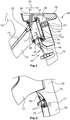
- Fig. 1 is a section of a time trial machine shown schematically.
- a top tube 10 is visible, which is connected to a down tube 12, wherein 12 shift cables 14 are arranged in the down tube.
- a control tube 16 an upper bearing 18 and a lower bearing 20 is arranged.
- the lower bearing 20 is supported by a bearing receptacle 22 designed as a bearing journal.
- the bearing receptacle 22 is formed integrally with a fork crown 24 in the illustrated embodiment.
- the fork crown 24 connects the two fork legs 26, which is in particular a made of composite material, in particular glass fiber reinforced fork, so that the fork crown 24 and the fork legs 26 are also integrally formed.
- the fork has a steerer 28, which is arranged in the direction of travel 30 in front of the head tube 16 and thus offset from the fork crown 24.
- An upper component 32 has a likewise journal-shaped bearing receptacle 34 for receiving the upper bearing 18 and thus forms the stem. Furthermore, the component 32 has a projection 36 which carries a bicycle handlebar 38, in the illustrated embodiment, a triathlon handlebars. Between the bearing receptacle 34 and the neck 36, a pointing in the direction of the steerer 28 approach 40 is provided. The projection 40 is connected via screws 42 to the steerer tube 28. The transmission of forces is not or at least only to a very small extent on the head tube 16, but on the steerer tube 28 and connected by means of screws 42 with the steerer 28 approach 40 of the stem 32. This makes it possible in the sleeve-shaped ausgestaltet Control tube 16 to provide an opening 17.
- An activation element such as a shift or brake cable 14 is passed through the opening 17 into the interior of the control tube 16.
- the trains 14, which may of course also be electrical lines, hydraulic line or the like, guided by the bearing receptacle 34 of the upper bearing 18 in the stem 32 and of this in the corresponding area of the handlebar 38.
- the activation elements 14 are thus arranged completely within the corresponding components and only emerge, for example, in the region of the front derailleur from the lower frame tube.
- the aerodynamics of the bicycle is significantly improved because no turbulence caused by external activation elements occur.
- a cable stop 19 is arranged in the illustrated embodiment.
- the cable stop 19 is designed such that, when Bowden cables are provided as activating elements 14, the sheaths of the Bowden cables end in the cable stop 19 and thus only the corresponding metal wires are arranged within the lower tube 12. These can be kept on tension, so that a rattling or knocking is avoided.
- the brake unit 44 has an actuating device 46 which can be actuated by a Bowden cable 48.
- the Bowden cable 48 passes through the fork crown 24 and the bearing seat 22 in the interior of the control tube 16. Next leads the Bowden cable 48 through the upper bearing 18 through and is guided from there to the handlebar 38 and the brake.
- the bearing receptacle 22 is closed at the top, so that a sleeve 50 of the Bowden cable 48 is disposed only within the head tube and leads to the brake lever.
- the sleeve 50 is held in a cylindrically shaped Buchendanschlag 52, which is preferably formed integrally with the bearing seat 22.
- the brake unit 44 is preferably arranged below an axis of rotation of the fork, the axis of rotation in the illustrated exemplary embodiment substantially coinciding with the sleeve 50 within the control tube 16.
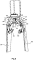
- the double bridge bicycle fork has two brake levers 58 ( Fig. 3 ), which are arranged within the fork legs 26 and the fork crown 24.
- the two brake levers are pivotally held by pivot axes 60, wherein the pivot axes 60 are also disposed within the fork legs 26 and the fork crown 24. If the two free brake lever ends 62 from the in Fig. 3 shown position in which no braking is pressed apart for braking, a movement of the two brake shoes 56 takes place inwardly in the direction of the rim, not shown.
- the actuator 44 is provided. This has a holding element 63 arranged within the fork crown.
- the holding element 63 carries two pivot axes 64, about the two each disposed within the holding element, in Fig. 3 dashed swivel lever 66 are pivotable.
- the pivot lever 66 are connected to the brake cable 48.
- the brake cable 48 in Fig. 3 By pulling the brake cable 48 in Fig. 3 to the top, there is thus a pivoting of the two pivot lever 66 to the outside.
- the free ends 62 of the brake lever 58 are pressed outwards, which in turn causes a movement of the two brake shoes inwardly in the direction of the rims.
- the substantially trapezoidal in plan view holding element 63 has two obliquely arranged side surfaces 68, against which the free ends 62 of the brake lever 58, when the brake is not actuated.
Landscapes
- Engineering & Computer Science (AREA)
- Mechanical Engineering (AREA)
- Steering Devices For Bicycles And Motorcycles (AREA)
- Flexible Shafts (AREA)
- Motorcycle And Bicycle Frame (AREA)
- Braking Arrangements (AREA)
Claims (8)
- Cadre de bicyclette avec un tube de guidage (16) et avec une fourche de bicyclette avec pont double reliée au tube de guidage (16), la fourche de bicyclette avec pont double comprenant- une couronne de fourche (24) reliant l'un à l'autre deux bras de fourche (26),- une réception de palier inférieure (22) reliée à la couronne de fourche (24),- une réception de palier supérieure (34) reliée à une avancée de guidon (32),- un tronc de fourche (28) décalé par rapport à la couronne de fourche (24), qui relie entre elles les deux réceptions de palier (22, 32) et- des éléments d'activation (14) pour des éléments de commande et/ou un frein de roue arrière, guidés entre les deux réceptions (32, 22) dans un élément de cadre (12) par un guidon (38) relié à l'avancée (32),
caractérisé en ce qu'au moins une partie des éléments d'activation (14) sont introduits à partir du guidon (38) directement dans l'avancée (32) et à partir de l'avancée (32) par la réception de palier supérieure (34) dans le tube de guidage (16), si bien que les éléments d'activation (14) soient disposés entièrement à l'intérieur du guidon (38), de l'avancée (32), du tube de guidage (16) et de l'élément de cadre (12). - Cadre de bicyclette avec fourche de bicyclette avec pont double selon la revendication 1, caractérisé en ce que le tronc de fourche (28) est attaché rigidement à l'avancée (32) et est notamment vissé.
- Cadre de bicyclette avec fourche de bicyclette avec pont double selon l'une des revendications 1 ou 2, caractérisé en ce qu'un manchon (50) est relié à la réception de palier supérieure (34), qui comprend une ouverture (17) pour faire passer les éléments d'activation (14), orientée en direction de l'élément de cadre (12).
- Cadre de bicyclette avec fourche de bicyclette avec pont double selon l'une des revendications 1 à 3, caractérisé en ce que le manchon (50) est relié à la réception de palier inférieure (22).
- Cadre de bicyclette avec fourche de bicyclette avec pont double selon l'une des revendications 1 à 4, caractérisé en ce qu'une unité de freinage (44) intégrée dans la fourche de bicyclette est disposée en-dessous de la couronne de fourche (24).
- Cadre de bicyclette avec fourche de bicyclette avec pont double selon la revendication 5, caractérisé en ce que l'unité de freinage (44) comprend deux leviers de freinage (58) qui sont disposés à l'intérieur des bras de fourche (26) et/ou de la couronne de fourche (24).
- Cadre de bicyclette avec fourche de bicyclette avec pont double selon la revendication 6, caractérisé en ce que les leviers de freinage (58) sont portés par des axes de pivotement (60) disposés à l'intérieur des bras de fourche (26) et/ou de la couronne de fourche (24).
- Cadre de bicyclette avec fourche de bicyclette avec pont double selon l'une des revendications 1 à 7, caractérisé en ce que la section transversale du bras de fourche (26) présente, au niveau d'un pneumatique monté, un rapport de longueur à largeur d'un maximum de 3:1.
Applications Claiming Priority (1)
| Application Number | Priority Date | Filing Date | Title |
|---|---|---|---|
| DE202011103814U DE202011103814U1 (de) | 2011-07-29 | 2011-07-29 | Doppelbrücken-Fahrradgabel |
Publications (3)
| Publication Number | Publication Date |
|---|---|
| EP2551179A2 EP2551179A2 (fr) | 2013-01-30 |
| EP2551179A3 EP2551179A3 (fr) | 2013-09-11 |
| EP2551179B1 true EP2551179B1 (fr) | 2016-12-21 |
Family
ID=46465118
Family Applications (1)
| Application Number | Title | Priority Date | Filing Date |
|---|---|---|---|
| EP12175241.4A Active EP2551179B1 (fr) | 2011-07-29 | 2012-07-06 | Cadre de bicyclette avec fourche de bicyclette avec pont double |
Country Status (3)
| Country | Link |
|---|---|
| US (1) | US20130026732A1 (fr) |
| EP (1) | EP2551179B1 (fr) |
| DE (1) | DE202011103814U1 (fr) |
Cited By (1)
| Publication number | Priority date | Publication date | Assignee | Title |
|---|---|---|---|---|
| DE202018004603U1 (de) | 2017-10-06 | 2018-10-22 | Airstreeem.com GmbH | Anordnung aus einem Rahmen für ein Fahrrad und einem Fahrradlenker |
Families Citing this family (8)
| Publication number | Priority date | Publication date | Assignee | Title |
|---|---|---|---|---|
| ITVI20110152A1 (it) * | 2011-06-09 | 2012-12-10 | Wilier Triestina S P A | Forcella per biciclette e bicicletta comprendente tale forcella |
| US9457867B2 (en) | 2013-03-14 | 2016-10-04 | Specialized Bicycle Components, Inc. | Bicycle brake assembly |
| US9701293B2 (en) | 2014-06-19 | 2017-07-11 | Specialized Bicycle Components, Inc. | Bicycle cable routing system |
| US9056646B1 (en) * | 2014-06-19 | 2015-06-16 | Specialized Bicycle Components, Inc. | Bicycle cable routing system |
| US10150530B2 (en) * | 2015-05-21 | 2018-12-11 | Trek Bicycle Corporation | Rigid frame with high-compliance seat tube and internal cable routing |
| US10029756B2 (en) | 2015-07-14 | 2018-07-24 | Duncan Bayard STOTHERS | Impact absorbing support for a wheel |
| US10906605B2 (en) | 2018-07-31 | 2021-02-02 | Trek Bicycle Corporation | Dual crown steering assembly |
| CN112478030A (zh) * | 2020-11-02 | 2021-03-12 | 杭州骏伟信息科技有限公司 | 一种动能回收可降温的自行车 |
Family Cites Families (20)
| Publication number | Priority date | Publication date | Assignee | Title |
|---|---|---|---|---|
| AT352554B (de) * | 1977-02-01 | 1979-09-25 | Steyr Daimler Puch Ag | Zweiradfahrzeug, insbesondere motorfahrrad |
| US4688749A (en) * | 1985-12-23 | 1987-08-25 | Cannondale Corporation | Bicycle brake cable stop and rear carrier rack attachment bracket |
| DE4131082A1 (de) * | 1990-12-10 | 1992-06-11 | Look Sa | Fahrrad-vorderradgabel aus einem verbundwerkstoff |
| US5692764A (en) * | 1993-08-13 | 1997-12-02 | Klein Bicycle Corporation | Bicycle front forks and methods of making same |
| US6186529B1 (en) * | 1998-05-27 | 2001-02-13 | Shimano Inc. | Bicycle brake mounting structure |
| US6308806B1 (en) * | 1999-09-13 | 2001-10-30 | Peter M. Nielsen | Brake assembly for a cycle |
| EP1518786A1 (fr) * | 2003-09-25 | 2005-03-30 | Giorgio Soglia | Frein de bicyclette |
| US7210694B2 (en) * | 2004-09-17 | 2007-05-01 | Rodney J Trenne | Integrated front fork hinge and brake system for bicycles |
| US7891687B2 (en) * | 2004-12-10 | 2011-02-22 | Magna Marque International Inc. | Method to conceal bicycle control cables within the handlebars, stem and frame |
| ITTO20050137U1 (it) * | 2005-09-16 | 2007-03-17 | Fioravanti Srl | Forcella di bicicletta con freno idraulico integrato. |
| TWM286174U (en) * | 2005-09-28 | 2006-01-21 | Shang-Ru Tsai | Bicycle frame structure capable of hiding brake |
| JP4164087B2 (ja) * | 2005-11-16 | 2008-10-08 | 株式会社シマノ | 自転車用ケーブル配索装置 |
| US7543835B2 (en) * | 2006-05-03 | 2009-06-09 | Trek Bicycle Corporation | Bicycle fork with improved steer tube and crown |
| CA2596762C (fr) * | 2006-08-10 | 2014-06-10 | Philip White | Fourche avec systeme de freinage integre |
| WO2009026721A1 (fr) * | 2007-08-30 | 2009-03-05 | Cycles Argon-18 Inc. | Ensemble de direction de bicyclette |
| US8438946B2 (en) * | 2008-06-06 | 2013-05-14 | Societe De Velo En Libre-Service | Handlebar for a bicycle |
| CA2725843A1 (fr) * | 2008-06-06 | 2009-12-10 | Societe De Velo En Libre-Service | Ensemble fourche pour bicyclette |
| US7837212B2 (en) * | 2009-02-25 | 2010-11-23 | Specialized Bicycle Components, Inc. | Handlebar stem for a bicycle |
| US8079609B2 (en) * | 2010-01-28 | 2011-12-20 | Felt Racing, Llc | Aerodynamic brake system |
| ITVI20110152A1 (it) * | 2011-06-09 | 2012-12-10 | Wilier Triestina S P A | Forcella per biciclette e bicicletta comprendente tale forcella |
-
2011
- 2011-07-29 DE DE202011103814U patent/DE202011103814U1/de not_active Expired - Lifetime
-
2012
- 2012-07-06 EP EP12175241.4A patent/EP2551179B1/fr active Active
- 2012-07-18 US US13/552,102 patent/US20130026732A1/en not_active Abandoned
Non-Patent Citations (1)
| Title |
|---|
| None * |
Cited By (1)
| Publication number | Priority date | Publication date | Assignee | Title |
|---|---|---|---|---|
| DE202018004603U1 (de) | 2017-10-06 | 2018-10-22 | Airstreeem.com GmbH | Anordnung aus einem Rahmen für ein Fahrrad und einem Fahrradlenker |
Also Published As
| Publication number | Publication date |
|---|---|
| DE202011103814U1 (de) | 2012-11-15 |
| EP2551179A2 (fr) | 2013-01-30 |
| EP2551179A3 (fr) | 2013-09-11 |
| US20130026732A1 (en) | 2013-01-31 |
Similar Documents
| Publication | Publication Date | Title |
|---|---|---|
| EP2551179B1 (fr) | Cadre de bicyclette avec fourche de bicyclette avec pont double | |
| DE112014004690B4 (de) | Zweirad mit einer Hinterradfederung | |
| EP2551178A1 (fr) | Fourche de vélo avec unité de freinage | |
| DE102010010317B4 (de) | Fahrradrahmen mit gelenkiger Gestänge-Befestigungsanordnung | |
| EP2706002B1 (fr) | Bicyclette à assistance électrique | |
| DE102014019816B4 (de) | Frontumwerfer | |
| DE102009011392B4 (de) | Fahrradsteuervorrichtung | |
| DE202011104974U1 (de) | Fahrradrahmen | |
| DE102013202979A1 (de) | Fahrradrahmen | |
| DE69922581T2 (de) | Fahrradrahmenteil mit einem Bremsmontageanordnung | |
| EP4124551B1 (fr) | Fourche de vélo, ainsi que système de fourche de vélo | |
| DE202019104711U1 (de) | Fahrrad-Lenkeinrichtung | |
| DE202013001399U1 (de) | Fahrradbetätigungsvorrichtung | |
| EP3260361B1 (fr) | Corps de guide de câble | |
| AT520501B1 (de) | Anordnung aus einem Rahmen für ein Fahrrad und einem Fahrradlenker | |
| EP2281739B1 (fr) | Cadre de bicyclette avec système d'exécution pour éléments de transmission de composants de vélo | |
| EP1919764A1 (fr) | Frein de velo de course et systeme de freinage pour freins de velo de course | |
| DE102015009813B4 (de) | Fahrradumwerfer | |
| DE3409779A1 (de) | Felgenbremse fuer fahrraeder | |
| EP4183670B1 (fr) | Butée de direction pour guidon de bicyclette | |
| DE102017118812B4 (de) | Verstärktes Viergelenk | |
| EP3535170B1 (fr) | Frein a inertie pour remorque avec barre de traction et roues | |
| EP3786046B1 (fr) | Système d'avant-corps | |
| EP3383732A1 (fr) | Ensemble guidon à intégration de fonctions pour une motocyclette | |
| DE19961176C2 (de) | Eine mit den Händen zu bedienende, kombinierte Kraftübertragungs- und Lenkeinrichtung an einem Fahrrad oder Dreirad |
Legal Events
| Date | Code | Title | Description |
|---|---|---|---|
| PUAI | Public reference made under article 153(3) epc to a published international application that has entered the european phase |
Free format text: ORIGINAL CODE: 0009012 |
|
| AK | Designated contracting states |
Kind code of ref document: A2 Designated state(s): AL AT BE BG CH CY CZ DE DK EE ES FI FR GB GR HR HU IE IS IT LI LT LU LV MC MK MT NL NO PL PT RO RS SE SI SK SM TR |
|
| AX | Request for extension of the european patent |
Extension state: BA ME |
|
| PUAL | Search report despatched |
Free format text: ORIGINAL CODE: 0009013 |
|
| AK | Designated contracting states |
Kind code of ref document: A3 Designated state(s): AL AT BE BG CH CY CZ DE DK EE ES FI FR GB GR HR HU IE IS IT LI LT LU LV MC MK MT NL NO PL PT RO RS SE SI SK SM TR |
|
| AX | Request for extension of the european patent |
Extension state: BA ME |
|
| RIC1 | Information provided on ipc code assigned before grant |
Ipc: B62K 21/06 20060101ALI20130808BHEP Ipc: B62L 1/16 20060101ALI20130808BHEP Ipc: B62K 19/38 20060101AFI20130808BHEP Ipc: B62K 21/02 20060101ALI20130808BHEP |
|
| 17P | Request for examination filed |
Effective date: 20140307 |
|
| RBV | Designated contracting states (corrected) |
Designated state(s): AL AT BE BG CH CY CZ DE DK EE ES FI FR GB GR HR HU IE IS IT LI LT LU LV MC MK MT NL NO PL PT RO RS SE SI SK SM TR |
|
| 17Q | First examination report despatched |
Effective date: 20141121 |
|
| GRAP | Despatch of communication of intention to grant a patent |
Free format text: ORIGINAL CODE: EPIDOSNIGR1 |
|
| INTG | Intention to grant announced |
Effective date: 20160706 |
|
| STAA | Information on the status of an ep patent application or granted ep patent |
Free format text: STATUS: GRANT OF PATENT IS INTENDED |
|
| GRAS | Grant fee paid |
Free format text: ORIGINAL CODE: EPIDOSNIGR3 |
|
| GRAA | (expected) grant |
Free format text: ORIGINAL CODE: 0009210 |
|
| STAA | Information on the status of an ep patent application or granted ep patent |
Free format text: STATUS: THE PATENT HAS BEEN GRANTED |
|
| AK | Designated contracting states |
Kind code of ref document: B1 Designated state(s): AL AT BE BG CH CY CZ DE DK EE ES FI FR GB GR HR HU IE IS IT LI LT LU LV MC MK MT NL NO PL PT RO RS SE SI SK SM TR |
|
| REG | Reference to a national code |
Ref country code: GB Ref legal event code: FG4D Free format text: NOT ENGLISH |
|
| REG | Reference to a national code |
Ref country code: CH Ref legal event code: EP |
|
| REG | Reference to a national code |
Ref country code: IE Ref legal event code: FG4D Free format text: LANGUAGE OF EP DOCUMENT: GERMAN |
|
| REG | Reference to a national code |
Ref country code: AT Ref legal event code: REF Ref document number: 855207 Country of ref document: AT Kind code of ref document: T Effective date: 20170115 |
|
| REG | Reference to a national code |
Ref country code: DE Ref legal event code: R096 Ref document number: 502012009073 Country of ref document: DE |
|
| PG25 | Lapsed in a contracting state [announced via postgrant information from national office to epo] |
Ref country code: LV Free format text: LAPSE BECAUSE OF FAILURE TO SUBMIT A TRANSLATION OF THE DESCRIPTION OR TO PAY THE FEE WITHIN THE PRESCRIBED TIME-LIMIT Effective date: 20161221 |
|
| REG | Reference to a national code |
Ref country code: LT Ref legal event code: MG4D |
|
| REG | Reference to a national code |
Ref country code: NL Ref legal event code: MP Effective date: 20161221 |
|
| PG25 | Lapsed in a contracting state [announced via postgrant information from national office to epo] |
Ref country code: NO Free format text: LAPSE BECAUSE OF FAILURE TO SUBMIT A TRANSLATION OF THE DESCRIPTION OR TO PAY THE FEE WITHIN THE PRESCRIBED TIME-LIMIT Effective date: 20170321 Ref country code: LT Free format text: LAPSE BECAUSE OF FAILURE TO SUBMIT A TRANSLATION OF THE DESCRIPTION OR TO PAY THE FEE WITHIN THE PRESCRIBED TIME-LIMIT Effective date: 20161221 Ref country code: SE Free format text: LAPSE BECAUSE OF FAILURE TO SUBMIT A TRANSLATION OF THE DESCRIPTION OR TO PAY THE FEE WITHIN THE PRESCRIBED TIME-LIMIT Effective date: 20161221 Ref country code: GR Free format text: LAPSE BECAUSE OF FAILURE TO SUBMIT A TRANSLATION OF THE DESCRIPTION OR TO PAY THE FEE WITHIN THE PRESCRIBED TIME-LIMIT Effective date: 20170322 |
|
| PG25 | Lapsed in a contracting state [announced via postgrant information from national office to epo] |
Ref country code: RS Free format text: LAPSE BECAUSE OF FAILURE TO SUBMIT A TRANSLATION OF THE DESCRIPTION OR TO PAY THE FEE WITHIN THE PRESCRIBED TIME-LIMIT Effective date: 20161221 Ref country code: FI Free format text: LAPSE BECAUSE OF FAILURE TO SUBMIT A TRANSLATION OF THE DESCRIPTION OR TO PAY THE FEE WITHIN THE PRESCRIBED TIME-LIMIT Effective date: 20161221 Ref country code: HR Free format text: LAPSE BECAUSE OF FAILURE TO SUBMIT A TRANSLATION OF THE DESCRIPTION OR TO PAY THE FEE WITHIN THE PRESCRIBED TIME-LIMIT Effective date: 20161221 |
|
| PG25 | Lapsed in a contracting state [announced via postgrant information from national office to epo] |
Ref country code: NL Free format text: LAPSE BECAUSE OF FAILURE TO SUBMIT A TRANSLATION OF THE DESCRIPTION OR TO PAY THE FEE WITHIN THE PRESCRIBED TIME-LIMIT Effective date: 20161221 |
|
| REG | Reference to a national code |
Ref country code: FR Ref legal event code: PLFP Year of fee payment: 6 |
|
| PG25 | Lapsed in a contracting state [announced via postgrant information from national office to epo] |
Ref country code: CZ Free format text: LAPSE BECAUSE OF FAILURE TO SUBMIT A TRANSLATION OF THE DESCRIPTION OR TO PAY THE FEE WITHIN THE PRESCRIBED TIME-LIMIT Effective date: 20161221 Ref country code: RO Free format text: LAPSE BECAUSE OF FAILURE TO SUBMIT A TRANSLATION OF THE DESCRIPTION OR TO PAY THE FEE WITHIN THE PRESCRIBED TIME-LIMIT Effective date: 20161221 Ref country code: EE Free format text: LAPSE BECAUSE OF FAILURE TO SUBMIT A TRANSLATION OF THE DESCRIPTION OR TO PAY THE FEE WITHIN THE PRESCRIBED TIME-LIMIT Effective date: 20161221 Ref country code: IS Free format text: LAPSE BECAUSE OF FAILURE TO SUBMIT A TRANSLATION OF THE DESCRIPTION OR TO PAY THE FEE WITHIN THE PRESCRIBED TIME-LIMIT Effective date: 20170421 Ref country code: SK Free format text: LAPSE BECAUSE OF FAILURE TO SUBMIT A TRANSLATION OF THE DESCRIPTION OR TO PAY THE FEE WITHIN THE PRESCRIBED TIME-LIMIT Effective date: 20161221 |
|
| PG25 | Lapsed in a contracting state [announced via postgrant information from national office to epo] |
Ref country code: BG Free format text: LAPSE BECAUSE OF FAILURE TO SUBMIT A TRANSLATION OF THE DESCRIPTION OR TO PAY THE FEE WITHIN THE PRESCRIBED TIME-LIMIT Effective date: 20170321 Ref country code: PT Free format text: LAPSE BECAUSE OF FAILURE TO SUBMIT A TRANSLATION OF THE DESCRIPTION OR TO PAY THE FEE WITHIN THE PRESCRIBED TIME-LIMIT Effective date: 20170421 Ref country code: IT Free format text: LAPSE BECAUSE OF FAILURE TO SUBMIT A TRANSLATION OF THE DESCRIPTION OR TO PAY THE FEE WITHIN THE PRESCRIBED TIME-LIMIT Effective date: 20161221 Ref country code: ES Free format text: LAPSE BECAUSE OF FAILURE TO SUBMIT A TRANSLATION OF THE DESCRIPTION OR TO PAY THE FEE WITHIN THE PRESCRIBED TIME-LIMIT Effective date: 20161221 Ref country code: SM Free format text: LAPSE BECAUSE OF FAILURE TO SUBMIT A TRANSLATION OF THE DESCRIPTION OR TO PAY THE FEE WITHIN THE PRESCRIBED TIME-LIMIT Effective date: 20161221 Ref country code: PL Free format text: LAPSE BECAUSE OF FAILURE TO SUBMIT A TRANSLATION OF THE DESCRIPTION OR TO PAY THE FEE WITHIN THE PRESCRIBED TIME-LIMIT Effective date: 20161221 |
|
| REG | Reference to a national code |
Ref country code: DE Ref legal event code: R097 Ref document number: 502012009073 Country of ref document: DE |
|
| PLBE | No opposition filed within time limit |
Free format text: ORIGINAL CODE: 0009261 |
|
| STAA | Information on the status of an ep patent application or granted ep patent |
Free format text: STATUS: NO OPPOSITION FILED WITHIN TIME LIMIT |
|
| 26N | No opposition filed |
Effective date: 20170922 |
|
| PG25 | Lapsed in a contracting state [announced via postgrant information from national office to epo] |
Ref country code: DK Free format text: LAPSE BECAUSE OF FAILURE TO SUBMIT A TRANSLATION OF THE DESCRIPTION OR TO PAY THE FEE WITHIN THE PRESCRIBED TIME-LIMIT Effective date: 20161221 |
|
| PG25 | Lapsed in a contracting state [announced via postgrant information from national office to epo] |
Ref country code: SI Free format text: LAPSE BECAUSE OF FAILURE TO SUBMIT A TRANSLATION OF THE DESCRIPTION OR TO PAY THE FEE WITHIN THE PRESCRIBED TIME-LIMIT Effective date: 20161221 |
|
| REG | Reference to a national code |
Ref country code: CH Ref legal event code: PL |
|
| REG | Reference to a national code |
Ref country code: IE Ref legal event code: MM4A |
|
| PG25 | Lapsed in a contracting state [announced via postgrant information from national office to epo] |
Ref country code: CH Free format text: LAPSE BECAUSE OF NON-PAYMENT OF DUE FEES Effective date: 20170731 Ref country code: LI Free format text: LAPSE BECAUSE OF NON-PAYMENT OF DUE FEES Effective date: 20170731 Ref country code: IE Free format text: LAPSE BECAUSE OF NON-PAYMENT OF DUE FEES Effective date: 20170706 |
|
| REG | Reference to a national code |
Ref country code: BE Ref legal event code: MM Effective date: 20170731 |
|
| PG25 | Lapsed in a contracting state [announced via postgrant information from national office to epo] |
Ref country code: LU Free format text: LAPSE BECAUSE OF NON-PAYMENT OF DUE FEES Effective date: 20170706 |
|
| REG | Reference to a national code |
Ref country code: FR Ref legal event code: PLFP Year of fee payment: 7 |
|
| PG25 | Lapsed in a contracting state [announced via postgrant information from national office to epo] |
Ref country code: BE Free format text: LAPSE BECAUSE OF NON-PAYMENT OF DUE FEES Effective date: 20170731 |
|
| REG | Reference to a national code |
Ref country code: AT Ref legal event code: MM01 Ref document number: 855207 Country of ref document: AT Kind code of ref document: T Effective date: 20170706 |
|
| PG25 | Lapsed in a contracting state [announced via postgrant information from national office to epo] |
Ref country code: MT Free format text: LAPSE BECAUSE OF FAILURE TO SUBMIT A TRANSLATION OF THE DESCRIPTION OR TO PAY THE FEE WITHIN THE PRESCRIBED TIME-LIMIT Effective date: 20161221 |
|
| PG25 | Lapsed in a contracting state [announced via postgrant information from national office to epo] |
Ref country code: AT Free format text: LAPSE BECAUSE OF NON-PAYMENT OF DUE FEES Effective date: 20170706 |
|
| PG25 | Lapsed in a contracting state [announced via postgrant information from national office to epo] |
Ref country code: MC Free format text: LAPSE BECAUSE OF FAILURE TO SUBMIT A TRANSLATION OF THE DESCRIPTION OR TO PAY THE FEE WITHIN THE PRESCRIBED TIME-LIMIT Effective date: 20161221 Ref country code: HU Free format text: LAPSE BECAUSE OF FAILURE TO SUBMIT A TRANSLATION OF THE DESCRIPTION OR TO PAY THE FEE WITHIN THE PRESCRIBED TIME-LIMIT; INVALID AB INITIO Effective date: 20120706 |
|
| PG25 | Lapsed in a contracting state [announced via postgrant information from national office to epo] |
Ref country code: CY Free format text: LAPSE BECAUSE OF NON-PAYMENT OF DUE FEES Effective date: 20161221 |
|
| PG25 | Lapsed in a contracting state [announced via postgrant information from national office to epo] |
Ref country code: MK Free format text: LAPSE BECAUSE OF FAILURE TO SUBMIT A TRANSLATION OF THE DESCRIPTION OR TO PAY THE FEE WITHIN THE PRESCRIBED TIME-LIMIT Effective date: 20161221 |
|
| PG25 | Lapsed in a contracting state [announced via postgrant information from national office to epo] |
Ref country code: TR Free format text: LAPSE BECAUSE OF FAILURE TO SUBMIT A TRANSLATION OF THE DESCRIPTION OR TO PAY THE FEE WITHIN THE PRESCRIBED TIME-LIMIT Effective date: 20161221 |
|
| PG25 | Lapsed in a contracting state [announced via postgrant information from national office to epo] |
Ref country code: AL Free format text: LAPSE BECAUSE OF FAILURE TO SUBMIT A TRANSLATION OF THE DESCRIPTION OR TO PAY THE FEE WITHIN THE PRESCRIBED TIME-LIMIT Effective date: 20161221 |
|
| P01 | Opt-out of the competence of the unified patent court (upc) registered |
Effective date: 20230420 |
|
| PGFP | Annual fee paid to national office [announced via postgrant information from national office to epo] |
Ref country code: DE Payment date: 20250717 Year of fee payment: 14 |
|
| PGFP | Annual fee paid to national office [announced via postgrant information from national office to epo] |
Ref country code: GB Payment date: 20250717 Year of fee payment: 14 |
|
| PGFP | Annual fee paid to national office [announced via postgrant information from national office to epo] |
Ref country code: FR Payment date: 20250723 Year of fee payment: 14 |