EP2281739B1 - Cadre de bicyclette avec système d'exécution pour éléments de transmission de composants de vélo - Google Patents
Cadre de bicyclette avec système d'exécution pour éléments de transmission de composants de vélo Download PDFInfo
- Publication number
- EP2281739B1 EP2281739B1 EP10171203A EP10171203A EP2281739B1 EP 2281739 B1 EP2281739 B1 EP 2281739B1 EP 10171203 A EP10171203 A EP 10171203A EP 10171203 A EP10171203 A EP 10171203A EP 2281739 B1 EP2281739 B1 EP 2281739B1
- Authority
- EP
- European Patent Office
- Prior art keywords
- tube
- opening
- hollow body
- bicycle
- frame
- Prior art date
- Legal status (The legal status is an assumption and is not a legal conclusion. Google has not performed a legal analysis and makes no representation as to the accuracy of the status listed.)
- Not-in-force
Links
Images




Classifications
-
- B—PERFORMING OPERATIONS; TRANSPORTING
- B62—LAND VEHICLES FOR TRAVELLING OTHERWISE THAN ON RAILS
- B62K—CYCLES; CYCLE FRAMES; CYCLE STEERING DEVICES; RIDER-OPERATED TERMINAL CONTROLS SPECIALLY ADAPTED FOR CYCLES; CYCLE AXLE SUSPENSIONS; CYCLE SIDECARS, FORECARS, OR THE LIKE
- B62K19/00—Cycle frames
- B62K19/30—Frame parts shaped to receive other cycle parts or accessories
-
- B—PERFORMING OPERATIONS; TRANSPORTING
- B62—LAND VEHICLES FOR TRAVELLING OTHERWISE THAN ON RAILS
- B62J—CYCLE SADDLES OR SEATS; AUXILIARY DEVICES OR ACCESSORIES SPECIALLY ADAPTED TO CYCLES AND NOT OTHERWISE PROVIDED FOR, e.g. ARTICLE CARRIERS OR CYCLE PROTECTORS
- B62J11/00—Supporting arrangements specially adapted for fastening specific devices to cycles, e.g. supports for attaching maps
- B62J11/10—Supporting arrangements specially adapted for fastening specific devices to cycles, e.g. supports for attaching maps for mechanical cables, hoses, pipes or electric wires, e.g. cable guides
- B62J11/13—Supporting arrangements specially adapted for fastening specific devices to cycles, e.g. supports for attaching maps for mechanical cables, hoses, pipes or electric wires, e.g. cable guides specially adapted for mechanical cables
Definitions
- the present invention relates to a transmission system of transmission components of bicycle components, as well as a bicycle with a sprung bicycle frame and a feedthrough system.
- a cable guide for bicycles known in which in a fork tube or a down tube of a bicycle frame a continuous guide tube for a cable or a Bowden cable is firmly used to make the insertion of the cable or the Bowden cable easier and to prevent ingress of moisture and to avoid dirt in the interior of the frame tube or fork.
- the cable guide on the fork has on the top of the shoulder region on an opening of the guide tube, which emerges on an underside of the fork tube again.
- the Bowden cable guide forms a guide tube, which enters the inside of the frame on the down tube on its upper side and exits again at the rear dropout on the underside.
- the DE 195 35 508 A1 relates to a fastening device for a bicycle headlamp, which is fastened with a screw, which penetrates the originally owned by the bicycle headlamp.
- the screw For cable routing, the screw has a longitudinal through hole.
- a transmission system of bicycle component transmission system comprising a bicycle frame having a tube construction of frame tubes, a transmission element passage, and at least one transmission element for controlling a bicycle component from the group of shifter cable, brake cable, hydraulic line or pneumatic line.
- At least one frame tube has in its lateral surface on a first opening and a second opening, wherein the at least one frame tube has a tube axis and the first opening with respect to the tube axis of the second opening substantially opposite.
- the first opening has a first edge region and the second opening has a second edge region, wherein a statically effective reinforcement of the first and / or second Edge area is provided.
- a passage opening of the transmission element passage is formed, and the at least one transmission element is arranged to pass through the passage opening.
- a reinforcement is, for example, an accumulation of material, wherein this reinforcement may be in the form of a ring, a disk or a bush, for example.
- the reinforcement may be attached to both the outer wall and on the inner wall of the lateral surface of the frame tube or on both walls.
- the reinforcement can be embodied as a separate component and accordingly firmly connected to the frame tube, for example by welding, soldering or gluing. It is also possible to carry out the reinforcement in one piece. In particular, in metal materials, these gains can also be generated by appropriate pressing operations.
- the reinforcement can be laminated in the corresponding edge regions of the opening, for example, or laminated on these edge regions or be taken into account already in the winding.
- the angle between an imaginary connection of the pipe axis with a center of the first opening and the imaginary connection between the center of the first opening and the center of the second opening of about ⁇ 15 ° to understand.
- an elongate hollow body having a first end with a first end face and with a second end with a second end face is provided in the feedthrough system.
- the first and the second end face each have an opening.
- the elongate hollow body connects the first opening of the frame tube and the second opening of the frame tube with each other and forms the transmission element passage.
- the elongated hollow body quasi forms a tunnel between the first opening and the second opening, so that transmission elements, such as hydraulic lines for disc or rim brakes, switching or brake cables, and power cables, for example, can be easily passed through the frame tube.
- the elongated hollow body forms a connection between the reinforced edge regions.
- this elongated hollow body can also be designed as a statically effective reinforcement at the same time so that further reinforcements can be omitted on the frame tube.
- the hollow body can be inserted into the interior space formed by the frame tube be so that the first and the second end face are each connected to the inner wall of the frame tube.
- the elongate hollow body is positioned relative to the first opening and the second opening in the frame tube in such a way that constrictions or projections are avoided. This ensures that the transmission elements can not get caught within the implementation.
- the elongated hollow body effectively reinforces the first and / or the second edge region.
- the elongated hollow body can be inserted from the outside through at least one of the two openings in the frame tube. It may be the elongated hollow body with an end face on the inner wall of the frame tube, while the first end face opposite the second end face is flush with the outer wall of the frame tube or extends beyond this. Of course, this end face also protrude relative to the outer wall such that the end of the elongate hollow body is held by the edge of the opening in the frame tube.
- the first and the second opening are arranged in tension and compression zones of the at least one frame tube, wherein according to a further embodiment of the invention, the elongated hollow body is integrally connected to the frame tube.
- a cohesive connection is here, for example, welding, for example, with or without welding solder, hard or soft soldering and gluing or laminating to understand.
- the one-piece and, possibly, batch-free production of such an elongate hollow body in a frame tube is to be understood by fabric closure.
- reinforcement of the edge regions of the first and the second opening can be produced in this material connection.
- a reinforcement produced in this way can offer an advantage, in particular, if the first and the second opening are mounted in zones of the bicycle frame which are subject to particular tensile and compressive stress, such as, for example, the top tube and / or the down tube.
- the elongate hollow body is introduced into the first opening and / or the second opening.
- the first and / or the second end of the elongated hollow body at least partially on a side outwardly facing projection.
- This projection can be formed on the end of the elongated hollow body of the material of the hollow body, so that the hollow body is made in one piece.
- the projection can also be designed as a separate component, which is fixedly connected to the elongated hollow body, for example by positive engagement, adhesion and / or material connection.
- the projection may be formed as a bead, fold, flanging, expansion, attached shoulder piece or as a nipple. Such a nipple can for example be done by squeezing a portion of the outer wall of the elongated hollow body at one end.
- the outward-facing projection can fulfill two tasks here.
- the projection can serve to allow the elongate hollow body to be inserted into the frame tube only to a certain extent through one of the two openings, which simplifies production.
- the projection can also be designed such that it assumes the functionality of the reinforcement.
- Such a shape design can offer advantages in welding, soldering, gluing or laminating.
- the inner wall of the elongated hollow body can also be composed of multiply curved surfaces, so that, for example, a trumpet shape or funnel shape is formed, which may also have polygonal and / or round sections in cross section.
- the projection is integrally connected to the frame tube of the bicycle frame.
- the elongated hollow body is formed as a one-piece pipe section.
- the inner wall of the elongated hollow body is parallel. If the inner wall of the pipe section consists of several subregions, the subregions run parallel to one another. As a representative of such pipe sections, for example, pipes with square, rectangular, oval, elliptical or even circular cross section should be mentioned at this point.
- the elongate hollow body has at least a first portion and a second portion, wherein the first portion and the second portion are connected together.
- interconnecting the first portion and the second portion not only means that the first portion is physically connected to the second portion, but also that the first portion is connected by means of an intermediate piece with the second portion.
- first portion through the first opening of the frame tube and the second portion through the second opening of the frame tube are inserted into a located in the frame tube interior center piece.
- the inner wall of the first and / or second section at least partially funnel-shaped and to connect them to a tubular center piece.
- the first portion, the second portion and the middle piece may be at least partially glued together.
- the first portion of the elongated hollow body at one of the first end surface opposite the first edge and the second portion of the elongated hollow body at a second end face opposite second edge each mating centering on such that an inner wall of the first portion with an inner wall of the second portion is aligned.
- the centering means may take the form of a projection on the edge opposite the first end face in the direction of longitudinal extension in conjunction with a corresponding recess on the edge of the second section opposite the second end face Longitudinal direction done.
- the centering means can also be formed, for example, such that the edge of the first section is cone-shaped in the longitudinal direction and centered in the correspondingly shaped edge of the second section.
- the elongated hollow body is connected to the frame tube dirt and moisture-proof.
- the at least one frame tube, in which the transmission element feedthrough is formed is a top tube, which is connected at one end to a seat tube.
- the seat tube of a seat tube center axis and the top tube have a top tube center axis which together form a frame plane.
- the elongated hollow body has a Hollow center axis, wherein the hollow body central axis lies in the frame plane.
- the elongated hollow body may be arranged in an upper tube which connects a steering head with the seat tube.
- the elongated hollow body in the top tube can be positioned such that transmission elements, such as shift cables or hydraulic lines, which are guided on the top of the top tube, are bent through the elongated hollow body in the direction of a bottom bracket along the seat tube.
- transmission elements such as shift cables or hydraulic lines
- Hydraulic lines laid in wide bends also have a higher durability due to less external force.
- the at least one frame tube is a top tube, wherein the elongated hollow body is arranged to the tube axis of the top tube at an angle between 10 ° and 80 °.
- an angle of 20 ° to 40 ° is particularly suitable to supply the hydraulic line for actuating the height-adjustable seatpost in a large arc ebendon seatpost without the hydraulic line affects the leg movement of the cyclist or that the hydraulic line collides with other moving mechanical components.
- the bicycle frame further comprises a bottom bracket and the second opening is closer to the bottom bracket arranged as the first opening, wherein the first opening is arranged closer to the seat tube than the second opening.
- Such positioning of the elongate hollow body in the vicinity of the seat tube makes it possible, for example, to guide transmission elements below a frame tube which connects a steering head to the seat tube and the transmission elements by means of the bushing according to the invention through the frame tube to a seat post connected to the seat tube supply.
- the hydraulic line of a handlebar to be operated from the ram which is mounted on a height-adjustable seat post, optimized position, protected against mechanical damage, such as scrubbing, and fed through the elongated implementation in a wide arc just this seat post.
- the elongated hollow body is dimensioned such that the required for actuating the height-adjustable seatpost hydraulic ram can be passed through the elongated hollow body without the ram must be released from the hydraulic line.
- a bicycle which has a sprung bicycle frame, with a top tube, a seat tube, a bottom bracket and a sprung rear triangle, which is pivotally mounted in the region of the bottom bracket about a lower pivot point and the upper part with a damped rear derailleur system is connected, which is held on the top tube and / or the seat tube such that a pivoting movement of the rear end about the lower pivot point is possible.
- a feedthrough system according to one of the preceding embodiments is provided, the transmission element implementation is arranged in the top tube and / or seat tube.
- the damped rear-end system on a rocker by means of which the rear end is held on the top tube, wherein the rocker has two lever which are pivotally held on the top tube laterally about a common axis of rotation.
- the transmission element implementation of the feedthrough system is arranged in the top tube in the region between the reversing levers.
- the transmission element is a hydraulic line of a saddle locking device.
- Suitable materials for the bicycle frame are metals, such as aluminum, titanium and steel, and its alloys and plastics, in particular fiber-reinforced, into consideration.
- the elongated hollow body, the two sections and the center piece may be made of metal, such as aluminum, titanium and steel, or its alloys and / or plastics, in particular fiber-reinforced. Furthermore, these parts can be made by machining or cutting. For example, the term “machining” means milling or turning. The term “non-cutting” is understood, for example, forming, prototyping, spraying or pouring.
- FIG. 1 shows a bicycle 78 with a sprung bicycle frame 2 having a top tube 8, a seat tube 6, a bottom bracket 7 and a sprung rear triangle 79, which is held pivotably in the region of the bottom bracket about a lower pivot point 77 and which is connected in the upper region with a damped rocker 80 of a rear end system 81.
- the rocker is held on the top tube so that a pivoting movement of the rear end about the lower pivot point is possible.
- the rocker has two lever 82, which are each pivotally held on the top tube laterally about a common axis of rotation, wherein in Fig. 1 only one side lever is visible; the other is covered by it.
- a transmission system implementing system 1 of bicycle components which comprises the bicycle frame 2 with a tube construction of frame tubes, a transmission element feedthrough 3 and at least one transmission element for controlling a bicycle component from the group of shift cable, brake cable, hydraulic line or pneumatic line.
- the transmission element feedthrough can be arranged, for example, in the top tube in the region between the deflection levers 82.
- a hydraulic line 70 is guided from the handlebar to a seat post as transmission elements, which has, for example, a hydraulically actuated adjusting mechanism.
- the hydraulic line 70 is passed between the rocker 80.
- the implementation of the hydraulic line through an example arranged in the top tube 8 elongated hollow body 24 is in Fig. 1 hidden by the rocker (see below).
- the transmission element for example the hydraulic line 70, as protected as possible, it runs in a first region A below the top tube.
- the transmission element extends above the top tube to engage with the bicycle component, in the example in FIG Fig. 2 an adjustable seatpost lock (not shown), to be connected.
- the transmission element feedthrough has a passage opening 5 through which the at least one transmission element is arranged to pass (not shown; Fig. 2 et seq.).
- FIG. 2 the bicycle frame 2 of the feedthrough system 1 is shown in a section.
- the bicycle frame 2 consists of a tubular construction of frame tubes. Shown here is the top tube 4, which is firmly connected to a seat tube 6.
- the top tube 4 is formed essentially by a lateral surface 8.
- the frame tube 4 has in its lateral surface 8 a first opening 10 and a second opening 12; wherein the at least one frame tube 4 has a tube axis 14 and the first opening 10 with respect to the tube axis 14 of the second opening 12 is substantially opposite.
- the first opening 10 has a first edge region 16 and the second opening 12 has a second edge region 18; wherein a statically effective reinforcement of the first 16 and / or second edge region 18 is provided.
- the passage opening of the transmission element passage is formed between the first and second openings.
- the hydraulic line 70, as Example of a transmission element is arranged leading through the feedthrough opening.
- An elongate hollow body 24 connects the first opening 10 and the second opening 12 with each other.
- the elongated hollow body has a first end face 30 at a first end 26 and a second end face 32 at its second end 28.
- both the first 30 and the second end face 32 each have an opening 34.
- the elongated hollow body (24) connects the first opening (10) and the second opening (12) with each other and forms the transmission element passage.
- the second end face 32 of the elongated hollow body 24 is flush with a bottom 68 of the frame tube 8.
- the elongate hollow body is welded to the frame tube 4 in the region of the second end face 32 and with the first end 26 with the lateral surface 8 in the two edge regions 16, 18.
- the weld seam 35 is set circumferentially.
- the hydraulic line 70 can be seen, which runs on the underside 68 of the top tube 8 and is fixed there by means of a fastening means 72.
- the hydraulic line 70 extends in a large arc through the elongated hollow body 24 to the seat tube 6.
- the hollow body has a hollow body central axis 74 which extends along the elongated hollow body 24.
- the tube axis 14 and the hollow body central axis 74 form an angle ⁇ of 10 ° to 80 °.
- the angle ⁇ is chosen here so that the large laying sheet of the hydraulic line 70 is not obstructed. In the exemplary embodiment present here, the angle ⁇ is approximately 20 ° to 40 °.
- the first opening 10 is arranged closer to the seat tube 6 than the opening 12.
- the seat tube 6 has a Wegrohrstoffachse 76, which together with the hollow body central axis 74 a plane spanned, so that thereby the position of the elongated hollow body 24 is determined to the seat tube 6.
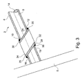
- FIG. 3 shows a section of the bicycle frame 2 with a further embodiment of the elongate hollow body 24.
- the longitudinal extent of the elongated hollow body 24 is greater than the height of the top tube 4, so that at least a portion of the two ends 26, 28 of the elongated hollow body 24th protrude beyond the jacket tube 8.
- the elongate hollow body 24 is positioned in the two openings 10, 12 in such a way that it protrudes uniformly over the lateral surface 8 with its two ends 26, 28.
- the two ends 26, 28 are welded to the lateral surface 4.
- the weld seam 35 forms in conjunction with the first edge region 16 of the first opening 10 and the second edge region 18 of the second opening 12, a third embodiment of a reinforcement 36.
- the elongated hollow body 24 is formed in this embodiment as a pipe section.
- FIG. 4 shows a section of a bicycle frame 2 with a further embodiment of the elongate hollow body 24. In the here shown
- a laterally outwardly facing projection 38 is formed at the second end 28 of the elongated hollow body 24 at the second end 28 of the elongated hollow body 24 .
- This projection 38 serves as a stop when inserting the elongated hollow body 24 in the top tube 4 and on the other hand as a further embodiment of a reinforcement of the second edge portion 18.
- the jacket tube 8 facing surface 39 of the first projection 38 is in the second edge region 18 of the outer contour of Lateral surface 8 adapted.
- the first end 26 is secured by a second projection 40.
- the second projection 40 is formed as a curved disc, which is materially connected to the first end 26 of the elongated hollow body 24 and the first edge region 16 of the lateral surface 8. Furthermore, the inner wall 42 of the elongated hollow body 24 in the present example is formed trumpet-shaped.
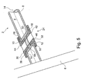
- FIG. 5 shows a section of a bicycle frame 2 with a further embodiment of the elongate hollow body 24, which is formed by a first portion 44, a second portion 46 and a middle piece 48.
- the first portion 44, the second portion 46 and the middle 48 are connected to each other.
- both sections 44, 46 of the projection 38 at the end 26, 28 of the respective portion 44, 46 is formed.
- the first portion 44 is inserted through the first opening 10 and the second portion 46 through the second opening 12 so far in the top tube 4 until the two projections 38 prevent further introduction.
- the center piece 48 connects the two sections 44 and 46 such that an inner wall 50 of the middle piece 48, the respective outer wall 52 of the two sections 44, 46 at least partially.
- the middle piece 48 to be integrally connected to the two sections 44, 46.
- the middle piece is shaped such that it produces an aligned inner wall 42 of the two sections 44, 46.
- FIG. 6 shows a section of a bicycle frame 2 with a further embodiment of the elongated hollow body 24.
- the elongated hollow body consists of a first portion 44 and a second portion 46.
- the first portion 44 has a first end surface 30 opposite the first edge 54.
- the second portion 46 has a second edge 56 opposite the second end surface 32.
- Formed at the first end 26 of the first portion 44 is a projection 38 which resembles a curved disk.
- the second portion 46 has at its second end 28 a projection 64, which is similar in this exemplary embodiment of a flange.
- Such a shaped projection 64 offers the advantage that no projecting edges or burrs are present at the opening 34 of the second end face 32 of the second section 46 due to the trumpet-shaped formation.
- first portion 44 is aligned with the second portion 46 by means of centering means 58 to each other such that the inner walls 42 of the two sections 44, 46 are aligned with each other.
- a projection 62 which engages in a recess 60 arranged on the second edge 56 of the second section 46, is arranged on the first edge 54.
- the two projections 38, 64 with the jacket tube 8 and the centering means 58 may be interconnected cohesively with each other.
- the elongate hollow body 24 as well as the sections 44, 46 forming it and the middle section 48 may be made of metal and its alloys as well as plastics, which may also be fiber-reinforced.
- the parts can be mechanical be manufactured, poured or sprayed.
- the bicycle frame 2 may be made of metal, such as titanium, aluminum or steel, and its alloys or fiber-reinforced, in particular carbon fiber reinforced plastic.
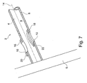
- the reinforcement 20 is formed integrally with the lateral surface 8 of the top tube 4.
- This reinforcement 20 is an accumulation of material that projects beyond the lateral surface 8.
- the second edge region 18 surrounding the second opening 12 is statically reinforced by means of a second embodiment of the reinforcement 22.
- the second embodiment of the reinforcement 22 is designed as a curved disc, which is glued over its entire surface with an inner wall 9 of the jacket tube 8.
- the length of the first opening 10, measured along the tube axis 14, is about 15 mm.
- the width of the first opening 10, measured transversely to the tube axis 14, is about 10 mm.
- the transmission element not shown, extends through the two openings from the bottom right obliquely to the top left.
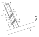
- FIG. 8 shows the already in FIG. 7 described section of the bicycle frame 2, wherein the elongated hollow body 24, the first opening 10 and the second opening 12 connects to each other.
- the cross section of the opening 34 is congruent with the cross section of the first opening 10 and the cross section of the second opening 12.
- the FIG. 8 can be seen that the elongated hollow body 24 with the first end face 30 in the first edge region 16 of the first opening 10 adjoins the inner wall 9 of the lateral surface 8.
- the second end face 32 of the elongated hollow body 24 adjacent to the reinforcement 22. So that the elongated hollow body 24 can not move within the top tube 8 along the tube axis 14, the two are End surfaces 30, 32 with the inner wall 9 of the lateral surface 8 and the reinforcement 22 materially bonded, glued in the present example here.
- the two edge portions 16, 18 of the openings 10, 12 in tensile and pressure-stressed frame tubes reinforce such that such openings 10, 12 regardless of their size in such zug- and pressure-loaded zones of Frame tube 8 can be arranged.
- the openings 10, 12 are connected by the elongated hollow body 24 with each other such that a tunnel between these openings 10, 12 is formed, are performed by the transmission elements such as shift and brake cables, hydraulic or pneumatic lines and electric cables through the frame tube can. Due to the position of the elongated hollow body, the transmission elements can be laid in a wide arc, so that they are not additionally burdened by additional forces caused by tight arches.
Landscapes
- Engineering & Computer Science (AREA)
- Mechanical Engineering (AREA)
- Motorcycle And Bicycle Frame (AREA)
Claims (14)
- Cadre de bicyclette avec un système de passage (1) pour des éléments de transmission de composants de bicyclette :dans lequel le cadre de bicyclette (2) comporte une structure en tubes, constituée de tubes de cadre (4, 6) ; etdans lequel il est prévu- un passage à éléments de transmission (3) ; et- au moins un élément de transmission (70) pour la commande d'un composant de bicyclette parmi le groupe incluant un câble, un frein, une conduite hydraulique ou une conduite pneumatique ;dans lequel au moins un tube de cadre (4) comporte une première ouverture (10) et une deuxième ouverture (12) dans sa surface périphérique (8) ; dans lequel l'au moins un tube de cadre (4) comporte un axe de tube (14), et la première ouverture (10) se trouve essentiellement en face de la deuxième ouverture (12) par rapport à l'axe de tube (14) ; et dans lequel la première ouverture (10) comporte une première région de bord (16) et la deuxième ouverture (12) comporte une deuxième région de bord (18) ;dans lequel est prévu un renforcement statique (20, 22, 36, 38, 40) de la première (16) et/ou de la deuxième région de bord (18) ;dans lequel une ouverture de passage (5) du passage d'éléments de transmission est formée entre la première et la deuxième ouverture ; etdans lequel l'au moins un élément de transmission (70) est agencé de manière à traverser l'ouverture de passage (5) ;dans lequel la première (10) et la deuxième ouverture (12) sont agencées dans des zones de l'au moins un tube de cadre (4) qui subissent une pression et une traction ;dans lequel l'au moins un tube de cadre est un tube supérieur (4), relié au tube d'assise (6) à une extrémité, et dans lequel est formé le passage d'éléments de transmission.
- Cadre de bicyclette selon la revendication 1, dans lequel un corps creux allongé (24) avec une première extrémité (26) comportant une première surface frontale (30) et avec une deuxième extrémité (28) comportant une deuxième surface frontale (32) ;
dans lequel la première (30) et la deuxième surface frontale (32) comportent chacune une ouverture (34) ; et
dans lequel le corps creux allongé (24) relie entre elles la première ouverture (10) et la deuxième ouverture (12), et forme le passage d'éléments de transmission. - Cadre de bicyclette selon la revendication 2, dans lequel le corps creux allongé (24) renforce la première (16) et/ou la deuxième région de bord (18) dans leur statique.
- Cadre de bicyclette selon la revendication 2 ou 3, dans lequel le corps creux allongé (24) est relié par liaison de matière au tube de cadre (4).
- Cadre de bicyclette selon l'une des revendications 2 à 4, dans lequel le corps creux allongé (24) est inséré dans la première ouverture (10) et/ou dans la deuxième ouverture (12).
- Cadre de bicyclette selon l'une des revendications 2 à 5, dans lequel la première (26) et/ou la deuxième extrémité (28) du corps creux allongé (24) comportent au moins partiellement une saillie (38, 40) orientée latéralement vers l'extérieur.
- Cadre de bicyclette selon l'une des revendications 2 à 6, dans lequel le corps creux allongé (24) comporte au moins une première pièce (44) et une deuxième pièce (46) ;
dans lequel la première pièce (44) et la deuxième pièce (46) sont reliées entre elles. - Cadre de bicyclette selon la revendication 7, dans lequel la première pièce (44) et la deuxième pièce (46) comportent respectivement des moyens de centrage (58) correspondants, respectivement sur un premier bord (54) opposé à la première surface frontale (30), et sur un deuxième bord (56) opposé à la deuxième surface frontale (32), de sorte qu'une paroi intérieure (42) de la première pièce (44) se trouve en affleurement avec la paroi intérieure (42) de la deuxième pièce (46).
- Cadre de bicyclette selon l'une des revendications 2 à 8, dans lequel le tube d'assise (6) comporte un axe médian de tube d'assise (76) et le tube supérieur comporte un axe médian de tube supérieur, qui ensemble déploient un plan de cadre ;
dans lequel le corps creux allongé (24) comporte un axe médian de corps creux allongé (74) ; et
dans lequel l'axe médian de corps creux allongé se trouve dans le plan du cadre. - Cadre de bicyclette selon l'une des revendications 2 à 9, dans lequel le corps creux allongé (24) est agencé de manière à former un angle α compris entre 10° et 80° par rapport à l'axe de tube (14) du tube supérieur (4).
- Cadre de bicyclette selon l'une des revendications 1 à 10, dans lequel le cadre de bicyclette comporte en outre un pédalier ;
dans lequel la deuxième ouverture (12) est prévue plus près du pédalier que la première ouverture (10) ; et
dans lequel la première ouverture (10) est prévue plus près du tube d'assise (6) que la deuxième ouverture (12). - Bicyclette avec un cadre de bicyclette sur ressorts (2), comportant un tube supérieur (8), un tube d'assise (4), un pédalier (7) et un train arrière sur ressorts (79) maintenu de façon à pouvoir pivoter, dans la région du pédalier, autour d'un point de rotation inférieur (5), tout en étant relié à un système de train arrière à amortisseur (81) dans la région supérieure, lequel est maintenu sur le tube supérieur et/ou le tube d'assise de manière à permettre un mouvement de pivotement du train arrière autour du point de rotation inférieur ; et
dans laquelle le cadre de bicyclette est conçu comme un cadre de bicyclette avec un système de passage (1) selon l'une des revendications 1 à 11, dont le passage d'éléments de transmission (3) est installé dans le tube supérieur et/ou le tube d'assise. - Bicyclette selon la revendication 12, dans laquelle le système de train arrière à amortisseur (81) comporte une bascule à amortisseur (80) avec deux leviers de déviation (82) maintenus de manière à pouvoir basculer latéralement sur le tube supérieur, autour d'un axe de rotation commun, tout en étant maintenus sur le tube supérieur au moyen du train arrière ;
dans laquelle le passage d'éléments de transmission (3) est prévu dans la région située entre les leviers de déviation (82). - Bicyclette selon la revendication 12 ou 13, dans laquelle l'élément de transmission (70) est une conduite hydraulique d'un dispositif de blocage de selle.
Applications Claiming Priority (1)
| Application Number | Priority Date | Filing Date | Title |
|---|---|---|---|
| DE102009035942A DE102009035942A1 (de) | 2009-08-03 | 2009-08-03 | Fahrradrahmen mit Durchführung |
Publications (3)
| Publication Number | Publication Date |
|---|---|
| EP2281739A2 EP2281739A2 (fr) | 2011-02-09 |
| EP2281739A3 EP2281739A3 (fr) | 2011-07-13 |
| EP2281739B1 true EP2281739B1 (fr) | 2013-01-02 |
Family
ID=43066783
Family Applications (1)
| Application Number | Title | Priority Date | Filing Date |
|---|---|---|---|
| EP10171203A Not-in-force EP2281739B1 (fr) | 2009-08-03 | 2010-07-29 | Cadre de bicyclette avec système d'exécution pour éléments de transmission de composants de vélo |
Country Status (3)
| Country | Link |
|---|---|
| US (1) | US8636294B2 (fr) |
| EP (1) | EP2281739B1 (fr) |
| DE (1) | DE102009035942A1 (fr) |
Families Citing this family (4)
| Publication number | Priority date | Publication date | Assignee | Title |
|---|---|---|---|---|
| US8882126B2 (en) * | 2013-03-06 | 2014-11-11 | Specialized Bicycle Components, Inc. | Bicycle frame with internal strut |
| CN203246553U (zh) * | 2013-03-09 | 2013-10-23 | 大行科技(深圳)有限公司 | 一种折叠自行车走线结构 |
| JP6850651B2 (ja) * | 2017-03-27 | 2021-03-31 | 本田技研工業株式会社 | 鞍乗り型車両 |
| JP7060488B2 (ja) * | 2018-10-15 | 2022-04-26 | ブリヂストンサイクル株式会社 | 自転車用フレーム |
Family Cites Families (22)
| Publication number | Priority date | Publication date | Assignee | Title |
|---|---|---|---|---|
| US724871A (en) * | 1901-01-07 | 1903-04-07 | Benjamin G Major | Spring-frame for bicycles. |
| DE876957C (de) | 1942-08-02 | 1953-05-18 | Union Sils Van De Loo & Co | Kabelfuehrung bei Fahr- und Motorraedern |
| GB606917A (en) | 1946-01-22 | 1948-08-23 | Walter William Greaves | Improvements in or connected with the construction of bicycle frames |
| US4102219A (en) * | 1977-08-19 | 1978-07-25 | Mtd Products Inc. | Fair-leads for a control wire |
| GB2136745B (en) * | 1983-03-21 | 1986-12-17 | Francis George Kirk | Lightweight bicycle frame |
| FR2575718B1 (fr) * | 1984-12-05 | 1990-08-24 | Honda Motor Co Ltd | Chassis pour vehicules a deux roues comprenant une paire de cadres principaux cloisonnes longitudinalement |
| US4768798A (en) * | 1987-04-03 | 1988-09-06 | Reed Curtis H | Internal cable arrangement for bicycle frame |
| US5054802A (en) * | 1989-04-28 | 1991-10-08 | Hedstrom Corporation | Bicycle frame |
| US5244224A (en) * | 1992-05-14 | 1993-09-14 | Gt Bicycles, Inc. | Rocker arm rear suspension bicycle |
| US5611557A (en) * | 1994-05-02 | 1997-03-18 | Farris; Mark S. | Bicycle suspension system |
| USRE39159E1 (en) * | 1995-01-25 | 2006-07-11 | Santa Cruz Bicycles, Inc. | Bicycle wheel travel path for selectively applying chainstay lengthening effect and apparatus for providing same |
| DE19535508A1 (de) * | 1995-09-25 | 1997-03-27 | Hans Schauff Fahrradfabrik | Befestigungsvorrichtung für einen Fahrradscheinwerfer |
| DE29603752U1 (de) * | 1996-02-29 | 1996-08-01 | MS Sport Vertriebs AG, Buochs | Fahrrad |
| US20030089144A1 (en) * | 2000-09-20 | 2003-05-15 | Hoffman Thomas W. | Bicycle cable locking system |
| US7073617B2 (en) * | 2001-12-28 | 2006-07-11 | Yamaha Hatsudoki Kabushiki Kaisha | Vehicle body frame for motorcycle |
| US6918606B2 (en) * | 2003-08-11 | 2005-07-19 | Radio Flyer Inc. | Tricycle push handle arrangement |
| US7377535B2 (en) * | 2004-10-29 | 2008-05-27 | Specialized Bicycle Components, Inc. | Bicycle frame |
| EP1803635B1 (fr) * | 2005-12-09 | 2009-03-25 | Prince Sports, Inc. | Bicyclette avec structure de cadre à tubes multiples |
| CN201062082Y (zh) * | 2007-04-20 | 2008-05-21 | 重庆宗申技术开发研究有限公司 | 摩托车主线缆安装结构 |
| US7850186B2 (en) * | 2008-03-26 | 2010-12-14 | Yuan-Chih Cheng | Bicycle frame with a receiving space |
| US7938425B2 (en) * | 2009-06-30 | 2011-05-10 | Specialized Bicycle Components, Inc. | Bicycle assembly with rear shock |
| US8196948B2 (en) * | 2010-01-25 | 2012-06-12 | Chi-Tien Chang | Elevating device for seat cushion of bicycle |
-
2009
- 2009-08-03 DE DE102009035942A patent/DE102009035942A1/de not_active Withdrawn
-
2010
- 2010-07-29 US US12/846,299 patent/US8636294B2/en not_active Expired - Fee Related
- 2010-07-29 EP EP10171203A patent/EP2281739B1/fr not_active Not-in-force
Also Published As
| Publication number | Publication date |
|---|---|
| US20110025017A1 (en) | 2011-02-03 |
| EP2281739A2 (fr) | 2011-02-09 |
| EP2281739A3 (fr) | 2011-07-13 |
| US8636294B2 (en) | 2014-01-28 |
| DE102009035942A1 (de) | 2011-02-10 |
Similar Documents
| Publication | Publication Date | Title |
|---|---|---|
| DE102014113842B4 (de) | Umwerfer | |
| DE102005052062A1 (de) | Fahrradrahmen | |
| EP2406122B1 (fr) | Élément de cadre pour le guidage d'un câble pour cadre de suspension de bicyclette | |
| DE102009032846B4 (de) | Motorrad mit einer mehrteiligen Rahmenanordnung | |
| DE102014013108B4 (de) | Fahrradklemmenstruktur und Fahrradbedienvorrichtung | |
| DE102020102695B4 (de) | Sitzschiene eines Motorrads | |
| EP2551179B1 (fr) | Cadre de bicyclette avec fourche de bicyclette avec pont double | |
| EP3676164B1 (fr) | Élément cylindrique creux et partie avant pour bicyclette, et bicyclette | |
| EP2281739B1 (fr) | Cadre de bicyclette avec système d'exécution pour éléments de transmission de composants de vélo | |
| EP3034386B1 (fr) | Insert pour ouverture dans un tube d'un cadre de deux roues | |
| DE102015221331B4 (de) | Vorderer Fahrrad-Kettenumwerfer mit Montagekonstruktion und Fahrradrahmen mit der Montagekonstruktion für den vorderen Fahrrad-Kettenumwerfer | |
| EP4124551A1 (fr) | Fourche de vélo, ainsi que système de fourche de vélo | |
| DE202022100922U1 (de) | Anordnung zum Verbinden eines Fahrradlenkers mit einer Fahrradgabel | |
| EP3260361B1 (fr) | Corps de guide de câble | |
| EP2551178A1 (fr) | Fourche de vélo avec unité de freinage | |
| DE102014106893B4 (de) | Umwerfer | |
| EP2772372B1 (fr) | Châssis pour un véhicule utilitaire et corps d'essieu | |
| EP2325072B1 (fr) | Fixation à câble pour vélo | |
| DE102015009813B4 (de) | Fahrradumwerfer | |
| DE29513779U1 (de) | Fahrrad | |
| DE102017118812B4 (de) | Verstärktes Viergelenk | |
| EP0764571B1 (fr) | Traverse d'essieu avant d'un véhicule automobile | |
| DE102015224134A1 (de) | Funktionsintegrierte Lenkeranordnung für ein Motorrad | |
| DE102020118209A1 (de) | Schelle | |
| DE102015218150B4 (de) | Verbindungsstruktur für Fahrzeugrahmenelemente |
Legal Events
| Date | Code | Title | Description |
|---|---|---|---|
| PUAI | Public reference made under article 153(3) epc to a published international application that has entered the european phase |
Free format text: ORIGINAL CODE: 0009012 |
|
| AK | Designated contracting states |
Kind code of ref document: A2 Designated state(s): AL AT BE BG CH CY CZ DE DK EE ES FI FR GB GR HR HU IE IS IT LI LT LU LV MC MK MT NL NO PL PT RO SE SI SK SM TR |
|
| AX | Request for extension of the european patent |
Extension state: BA ME RS |
|
| PUAL | Search report despatched |
Free format text: ORIGINAL CODE: 0009013 |
|
| AK | Designated contracting states |
Kind code of ref document: A3 Designated state(s): AL AT BE BG CH CY CZ DE DK EE ES FI FR GB GR HR HU IE IS IT LI LT LU LV MC MK MT NL NO PL PT RO SE SI SK SM TR |
|
| AX | Request for extension of the european patent |
Extension state: BA ME RS |
|
| 17P | Request for examination filed |
Effective date: 20111215 |
|
| GRAP | Despatch of communication of intention to grant a patent |
Free format text: ORIGINAL CODE: EPIDOSNIGR1 |
|
| GRAS | Grant fee paid |
Free format text: ORIGINAL CODE: EPIDOSNIGR3 |
|
| GRAA | (expected) grant |
Free format text: ORIGINAL CODE: 0009210 |
|
| AK | Designated contracting states |
Kind code of ref document: B1 Designated state(s): AL AT BE BG CH CY CZ DE DK EE ES FI FR GB GR HR HU IE IS IT LI LT LU LV MC MK MT NL NO PL PT RO SE SI SK SM TR |
|
| REG | Reference to a national code |
Ref country code: GB Ref legal event code: FG4D Free format text: NOT ENGLISH |
|
| REG | Reference to a national code |
Ref country code: AT Ref legal event code: REF Ref document number: 591442 Country of ref document: AT Kind code of ref document: T Effective date: 20130115 Ref country code: CH Ref legal event code: EP |
|
| REG | Reference to a national code |
Ref country code: IE Ref legal event code: FG4D Free format text: LANGUAGE OF EP DOCUMENT: GERMAN |
|
| REG | Reference to a national code |
Ref country code: DE Ref legal event code: R096 Ref document number: 502010002012 Country of ref document: DE Effective date: 20130228 |
|
| REG | Reference to a national code |
Ref country code: NL Ref legal event code: VDEP Effective date: 20130102 |
|
| PG25 | Lapsed in a contracting state [announced via postgrant information from national office to epo] |
Ref country code: SI Free format text: LAPSE BECAUSE OF FAILURE TO SUBMIT A TRANSLATION OF THE DESCRIPTION OR TO PAY THE FEE WITHIN THE PRESCRIBED TIME-LIMIT Effective date: 20130102 |
|
| REG | Reference to a national code |
Ref country code: LT Ref legal event code: MG4D |
|
| PG25 | Lapsed in a contracting state [announced via postgrant information from national office to epo] |
Ref country code: ES Free format text: LAPSE BECAUSE OF FAILURE TO SUBMIT A TRANSLATION OF THE DESCRIPTION OR TO PAY THE FEE WITHIN THE PRESCRIBED TIME-LIMIT Effective date: 20130413 Ref country code: BG Free format text: LAPSE BECAUSE OF FAILURE TO SUBMIT A TRANSLATION OF THE DESCRIPTION OR TO PAY THE FEE WITHIN THE PRESCRIBED TIME-LIMIT Effective date: 20130402 Ref country code: CZ Free format text: LAPSE BECAUSE OF FAILURE TO SUBMIT A TRANSLATION OF THE DESCRIPTION OR TO PAY THE FEE WITHIN THE PRESCRIBED TIME-LIMIT Effective date: 20130102 Ref country code: IS Free format text: LAPSE BECAUSE OF FAILURE TO SUBMIT A TRANSLATION OF THE DESCRIPTION OR TO PAY THE FEE WITHIN THE PRESCRIBED TIME-LIMIT Effective date: 20130502 Ref country code: SE Free format text: LAPSE BECAUSE OF FAILURE TO SUBMIT A TRANSLATION OF THE DESCRIPTION OR TO PAY THE FEE WITHIN THE PRESCRIBED TIME-LIMIT Effective date: 20130102 Ref country code: NO Free format text: LAPSE BECAUSE OF FAILURE TO SUBMIT A TRANSLATION OF THE DESCRIPTION OR TO PAY THE FEE WITHIN THE PRESCRIBED TIME-LIMIT Effective date: 20130402 Ref country code: LT Free format text: LAPSE BECAUSE OF FAILURE TO SUBMIT A TRANSLATION OF THE DESCRIPTION OR TO PAY THE FEE WITHIN THE PRESCRIBED TIME-LIMIT Effective date: 20130102 |
|
| PG25 | Lapsed in a contracting state [announced via postgrant information from national office to epo] |
Ref country code: FI Free format text: LAPSE BECAUSE OF FAILURE TO SUBMIT A TRANSLATION OF THE DESCRIPTION OR TO PAY THE FEE WITHIN THE PRESCRIBED TIME-LIMIT Effective date: 20130102 Ref country code: LV Free format text: LAPSE BECAUSE OF FAILURE TO SUBMIT A TRANSLATION OF THE DESCRIPTION OR TO PAY THE FEE WITHIN THE PRESCRIBED TIME-LIMIT Effective date: 20130102 Ref country code: PL Free format text: LAPSE BECAUSE OF FAILURE TO SUBMIT A TRANSLATION OF THE DESCRIPTION OR TO PAY THE FEE WITHIN THE PRESCRIBED TIME-LIMIT Effective date: 20130102 Ref country code: GR Free format text: LAPSE BECAUSE OF FAILURE TO SUBMIT A TRANSLATION OF THE DESCRIPTION OR TO PAY THE FEE WITHIN THE PRESCRIBED TIME-LIMIT Effective date: 20130403 Ref country code: NL Free format text: LAPSE BECAUSE OF FAILURE TO SUBMIT A TRANSLATION OF THE DESCRIPTION OR TO PAY THE FEE WITHIN THE PRESCRIBED TIME-LIMIT Effective date: 20130102 Ref country code: PT Free format text: LAPSE BECAUSE OF FAILURE TO SUBMIT A TRANSLATION OF THE DESCRIPTION OR TO PAY THE FEE WITHIN THE PRESCRIBED TIME-LIMIT Effective date: 20130502 |
|
| PG25 | Lapsed in a contracting state [announced via postgrant information from national office to epo] |
Ref country code: HR Free format text: LAPSE BECAUSE OF FAILURE TO SUBMIT A TRANSLATION OF THE DESCRIPTION OR TO PAY THE FEE WITHIN THE PRESCRIBED TIME-LIMIT Effective date: 20130102 |
|
| PG25 | Lapsed in a contracting state [announced via postgrant information from national office to epo] |
Ref country code: SK Free format text: LAPSE BECAUSE OF FAILURE TO SUBMIT A TRANSLATION OF THE DESCRIPTION OR TO PAY THE FEE WITHIN THE PRESCRIBED TIME-LIMIT Effective date: 20130102 Ref country code: DK Free format text: LAPSE BECAUSE OF FAILURE TO SUBMIT A TRANSLATION OF THE DESCRIPTION OR TO PAY THE FEE WITHIN THE PRESCRIBED TIME-LIMIT Effective date: 20130102 Ref country code: RO Free format text: LAPSE BECAUSE OF FAILURE TO SUBMIT A TRANSLATION OF THE DESCRIPTION OR TO PAY THE FEE WITHIN THE PRESCRIBED TIME-LIMIT Effective date: 20130102 Ref country code: EE Free format text: LAPSE BECAUSE OF FAILURE TO SUBMIT A TRANSLATION OF THE DESCRIPTION OR TO PAY THE FEE WITHIN THE PRESCRIBED TIME-LIMIT Effective date: 20130102 |
|
| PLBE | No opposition filed within time limit |
Free format text: ORIGINAL CODE: 0009261 |
|
| STAA | Information on the status of an ep patent application or granted ep patent |
Free format text: STATUS: NO OPPOSITION FILED WITHIN TIME LIMIT |
|
| PG25 | Lapsed in a contracting state [announced via postgrant information from national office to epo] |
Ref country code: CY Free format text: LAPSE BECAUSE OF FAILURE TO SUBMIT A TRANSLATION OF THE DESCRIPTION OR TO PAY THE FEE WITHIN THE PRESCRIBED TIME-LIMIT Effective date: 20130102 |
|
| 26N | No opposition filed |
Effective date: 20131003 |
|
| PG25 | Lapsed in a contracting state [announced via postgrant information from national office to epo] |
Ref country code: IT Free format text: LAPSE BECAUSE OF FAILURE TO SUBMIT A TRANSLATION OF THE DESCRIPTION OR TO PAY THE FEE WITHIN THE PRESCRIBED TIME-LIMIT Effective date: 20130102 |
|
| REG | Reference to a national code |
Ref country code: DE Ref legal event code: R097 Ref document number: 502010002012 Country of ref document: DE Effective date: 20131003 |
|
| BERE | Be: lapsed |
Owner name: KLIEBER, JOCHEN Effective date: 20130731 |
|
| PG25 | Lapsed in a contracting state [announced via postgrant information from national office to epo] |
Ref country code: MC Free format text: LAPSE BECAUSE OF FAILURE TO SUBMIT A TRANSLATION OF THE DESCRIPTION OR TO PAY THE FEE WITHIN THE PRESCRIBED TIME-LIMIT Effective date: 20130102 |
|
| REG | Reference to a national code |
Ref country code: IE Ref legal event code: MM4A |
|
| REG | Reference to a national code |
Ref country code: FR Ref legal event code: ST Effective date: 20140331 |
|
| PG25 | Lapsed in a contracting state [announced via postgrant information from national office to epo] |
Ref country code: BE Free format text: LAPSE BECAUSE OF NON-PAYMENT OF DUE FEES Effective date: 20130731 |
|
| PG25 | Lapsed in a contracting state [announced via postgrant information from national office to epo] |
Ref country code: FR Free format text: LAPSE BECAUSE OF NON-PAYMENT OF DUE FEES Effective date: 20130731 |
|
| PG25 | Lapsed in a contracting state [announced via postgrant information from national office to epo] |
Ref country code: IE Free format text: LAPSE BECAUSE OF NON-PAYMENT OF DUE FEES Effective date: 20130729 |
|
| REG | Reference to a national code |
Ref country code: CH Ref legal event code: PL |
|
| GBPC | Gb: european patent ceased through non-payment of renewal fee |
Effective date: 20140729 |
|
| PG25 | Lapsed in a contracting state [announced via postgrant information from national office to epo] |
Ref country code: CH Free format text: LAPSE BECAUSE OF NON-PAYMENT OF DUE FEES Effective date: 20140731 Ref country code: LI Free format text: LAPSE BECAUSE OF NON-PAYMENT OF DUE FEES Effective date: 20140731 |
|
| PG25 | Lapsed in a contracting state [announced via postgrant information from national office to epo] |
Ref country code: GB Free format text: LAPSE BECAUSE OF NON-PAYMENT OF DUE FEES Effective date: 20140729 Ref country code: SM Free format text: LAPSE BECAUSE OF FAILURE TO SUBMIT A TRANSLATION OF THE DESCRIPTION OR TO PAY THE FEE WITHIN THE PRESCRIBED TIME-LIMIT Effective date: 20130102 |
|
| PG25 | Lapsed in a contracting state [announced via postgrant information from national office to epo] |
Ref country code: MT Free format text: LAPSE BECAUSE OF FAILURE TO SUBMIT A TRANSLATION OF THE DESCRIPTION OR TO PAY THE FEE WITHIN THE PRESCRIBED TIME-LIMIT Effective date: 20130102 Ref country code: TR Free format text: LAPSE BECAUSE OF FAILURE TO SUBMIT A TRANSLATION OF THE DESCRIPTION OR TO PAY THE FEE WITHIN THE PRESCRIBED TIME-LIMIT Effective date: 20130102 |
|
| PG25 | Lapsed in a contracting state [announced via postgrant information from national office to epo] |
Ref country code: HU Free format text: LAPSE BECAUSE OF FAILURE TO SUBMIT A TRANSLATION OF THE DESCRIPTION OR TO PAY THE FEE WITHIN THE PRESCRIBED TIME-LIMIT; INVALID AB INITIO Effective date: 20100729 Ref country code: MK Free format text: LAPSE BECAUSE OF FAILURE TO SUBMIT A TRANSLATION OF THE DESCRIPTION OR TO PAY THE FEE WITHIN THE PRESCRIBED TIME-LIMIT Effective date: 20130102 Ref country code: LU Free format text: LAPSE BECAUSE OF NON-PAYMENT OF DUE FEES Effective date: 20130729 |
|
| REG | Reference to a national code |
Ref country code: AT Ref legal event code: MM01 Ref document number: 591442 Country of ref document: AT Kind code of ref document: T Effective date: 20150729 |
|
| PG25 | Lapsed in a contracting state [announced via postgrant information from national office to epo] |
Ref country code: AT Free format text: LAPSE BECAUSE OF NON-PAYMENT OF DUE FEES Effective date: 20150729 |
|
| REG | Reference to a national code |
Ref country code: DE Ref legal event code: R084 Ref document number: 502010002012 Country of ref document: DE |
|
| REG | Reference to a national code |
Ref country code: DE Ref legal event code: R082 Ref document number: 502010002012 Country of ref document: DE Representative=s name: WBH WACHENHAUSEN PATENTANWAELTE PARTG MBB, DE Ref country code: DE Ref legal event code: R082 Ref document number: 502010002012 Country of ref document: DE Representative=s name: WACHENHAUSEN & KOLLEGEN PATENTANWAELTE GBR, DE |
|
| PG25 | Lapsed in a contracting state [announced via postgrant information from national office to epo] |
Ref country code: AL Free format text: LAPSE BECAUSE OF FAILURE TO SUBMIT A TRANSLATION OF THE DESCRIPTION OR TO PAY THE FEE WITHIN THE PRESCRIBED TIME-LIMIT Effective date: 20130102 |
|
| P01 | Opt-out of the competence of the unified patent court (upc) registered |
Effective date: 20230601 |
|
| PGFP | Annual fee paid to national office [announced via postgrant information from national office to epo] |
Ref country code: DE Payment date: 20230720 Year of fee payment: 14 |
|
| REG | Reference to a national code |
Ref country code: DE Ref legal event code: R119 Ref document number: 502010002012 Country of ref document: DE |
|
| PG25 | Lapsed in a contracting state [announced via postgrant information from national office to epo] |
Ref country code: DE Free format text: LAPSE BECAUSE OF NON-PAYMENT OF DUE FEES Effective date: 20250201 |