EP2551401A1 - Wärmepumpensystem für Wäschetrockner - Google Patents
Wärmepumpensystem für Wäschetrockner Download PDFInfo
- Publication number
- EP2551401A1 EP2551401A1 EP11175681A EP11175681A EP2551401A1 EP 2551401 A1 EP2551401 A1 EP 2551401A1 EP 11175681 A EP11175681 A EP 11175681A EP 11175681 A EP11175681 A EP 11175681A EP 2551401 A1 EP2551401 A1 EP 2551401A1
- Authority
- EP
- European Patent Office
- Prior art keywords
- heat exchanger
- refrigerant
- pump system
- heat pump
- compressor
- Prior art date
- Legal status (The legal status is an assumption and is not a legal conclusion. Google has not performed a legal analysis and makes no representation as to the accuracy of the status listed.)
- Withdrawn
Links
- 239000003507 refrigerant Substances 0.000 claims abstract description 141
- 238000003475 lamination Methods 0.000 claims abstract description 47
- CURLTUGMZLYLDI-UHFFFAOYSA-N Carbon dioxide Chemical compound O=C=O CURLTUGMZLYLDI-UHFFFAOYSA-N 0.000 claims description 53
- 229910002092 carbon dioxide Inorganic materials 0.000 claims description 27
- 239000001569 carbon dioxide Substances 0.000 claims description 27
- 238000001816 cooling Methods 0.000 claims description 9
- 238000010438 heat treatment Methods 0.000 claims description 8
- 239000007789 gas Substances 0.000 description 82
- 239000003570 air Substances 0.000 description 43
- 239000012071 phase Substances 0.000 description 35
- 238000001035 drying Methods 0.000 description 22
- 238000010586 diagram Methods 0.000 description 18
- 230000006835 compression Effects 0.000 description 15
- 238000007906 compression Methods 0.000 description 15
- 238000000034 method Methods 0.000 description 5
- 230000008569 process Effects 0.000 description 5
- 230000008859 change Effects 0.000 description 4
- 230000003247 decreasing effect Effects 0.000 description 3
- 239000007788 liquid Substances 0.000 description 3
- 238000001704 evaporation Methods 0.000 description 2
- 230000008020 evaporation Effects 0.000 description 2
- 239000007792 gaseous phase Substances 0.000 description 2
- 238000012986 modification Methods 0.000 description 2
- 230000004048 modification Effects 0.000 description 2
- 239000012080 ambient air Substances 0.000 description 1
- 238000005265 energy consumption Methods 0.000 description 1
- 238000005516 engineering process Methods 0.000 description 1
- 239000012530 fluid Substances 0.000 description 1
- 230000003993 interaction Effects 0.000 description 1
- 239000007791 liquid phase Substances 0.000 description 1
- 239000000203 mixture Substances 0.000 description 1
- 230000004044 response Effects 0.000 description 1
- 230000001052 transient effect Effects 0.000 description 1
- XLYOFNOQVPJJNP-UHFFFAOYSA-N water Substances O XLYOFNOQVPJJNP-UHFFFAOYSA-N 0.000 description 1
Images


Classifications
-
- D—TEXTILES; PAPER
- D06—TREATMENT OF TEXTILES OR THE LIKE; LAUNDERING; FLEXIBLE MATERIALS NOT OTHERWISE PROVIDED FOR
- D06F—LAUNDERING, DRYING, IRONING, PRESSING OR FOLDING TEXTILE ARTICLES
- D06F58/00—Domestic laundry dryers
- D06F58/20—General details of domestic laundry dryers
- D06F58/206—Heat pump arrangements
Definitions
- the present invention relates to a heat pump system for a laundry dryer according to the preamble of claim 1. Further, the present invention relates to a corresponding laundry dryer.
- the heat pump technology is at present the most efficient way to dry clothes in terms of energy consumption.
- an air stream flows in a close air stream circuit.
- the air stream is moved by a fan, passes through a laundry chamber, which is preferably formed as a rotatable laundry drum, removes water from wet clothes, is then cooled down and dehumidified in a heat pump evaporator, heated up in a heat pump condenser and at last re-inserted into the laundry drum again.
- the refrigerant instead is compressed by a compressor, condensed in the condenser, laminated in an expansion device and then vaporized in the evaporator. Therefore the temperatures of the air stream and the refrigerant are strictly connected each other.
- the cycle of the heat pump laundry dryer is characterized by two phases: a transitory phase or warm-up phase and a steady state phase.
- a transitory phase the temperatures of the air stream and the refrigerant, which are usually at an ambient temperature when the system begins to operate, increase up to a desired level.
- the steady state phase the temperatures of the air stream and the refrigerant are kept almost constant.
- a cooling fan cools down the compressor or an auxiliary condenser, which removes excess heat from the heat pump system, in order to keep the temperatures of the air stream and the refrigerant constant until the laundry is dried.
- the traditional condenser in which the refrigerant coming from the outlet of the compressor condensates while the air stream is heated up, is substituted by a gas cooler, in which the carbon dioxide is cooled down while the air stream is heated up.
- a gas cooler At the gas cooler outlet there is no refrigerant in liquid state, but a gas with a lower temperature and an increased density.
- there could be a very short transient phase i.e. a few seconds or a few minutes, after the switching on the compressor in which the refrigerant is in the liquid phase in the high pressure portion of the heat pump circuit.
- the heat pump system can be forced working in a totally-supercritical cycle.
- the refrigerant is kept always in a gaseous phase, also in a low pressure portion of the heat pump circuit.
- the evaporator is called gas heater, since the carbon dioxide is heated up without change of phase.
- the terms evaporator and gas heater are hereinafter used as synonymous.
- FIG 3 shows a temperature-entropy diagram of carbon dioxide in the trans-critical cycle.
- FIG 4 shows the temperature-entropy diagram of carbon dioxide in the totally-supercritical cycle.
- the temperature-entropy diagrams comprise a high pressure isobaric line 40, a low pressure isobaric line 42, a saturation curve 44 of carbon dioxide, a compression phase 46 and a lamination phase 48. Further, a state a of the refrigerant at the gas heater outlet, a state b of the refrigerant at the gas cooler inlet, a state c of the refrigerant at the gas cooler outlet and a state d of the refrigerant at the gas heater inlet are indicated in the temperature-entropy diagrams.
- the temperature and pressure of carbon dioxide increase.
- the carbon dioxide follows the high pressure isobaric line 40.
- the lamination phase 48 the temperature and pressure of carbon dioxide decrease.
- the carbon dioxide follows the low pressure isobaric line 42.
- the evaporation phase following the low pressure isobaric line 42 from the state d, wherein the pressure and temperature stay constant, is avoided. Therefore the temperature difference between the refrigerant and the air stream, which has to be cooled down for dehumidifying the moisture air stream, is reduced. Thus, the performances of the gas heater are improved.
- the phases following the high pressure isobaric line 40 and the low pressure isobaric line 42, respectively, are "shorter" in FIG 4 .
- the main one is connected to the fact that the temperature of the refrigerant at the inlet of the gas heater is greater than the temperature of the refrigerant at the inlet of the gas heater during the trans-critical cycle. This reduces the capacity of the refrigerant for dehumidifying the air stream.
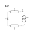
- FIG 5 shows a refrigerant circuit according to the prior art.
- the refrigerant circuit includes a compressor 14 form as double stage compressor. Further, the refrigerant circuit includes a gas cooler 16, lamination means 18 and an evaporator 22.
- the double stage compressor 14 is characterized by having two inlets and two outlets, namely a low pressure suction, an intermediate pressure discharge, an intermediate pressure suction and a high pressure discharge. For usual heat pump applications, the intermediate pressure discharge and the intermediate pressure suction are welded together, so that the compressor behaves as one single stage compressor.
- the heat pump system of the laundry dryer using carbon dioxide as refrigerant can work in a trans-critical or total-supercritical cycle. Both cycle processes present some advantages and disadvantages due to the heat pump performances and the interaction between the refrigerant and the air stream.
- the object of the present invention is achieved by the heat pump system according to claim 1.
- the present invention provides a heat pump system, wherein the structure of the refrigerant circuit results in three portions of said refrigerant circuit with different pressure levels.
- the structure of the refrigerant circuit allows that the heat pump system can works in the totally-supercritical cycle and the trans-critical cycle at the same time, so that the advantages of said totally-supercritical cycle and trans-critical cycle are connected.
- the refrigerant in the refrigerant circuit is carbon dioxide.
- the refrigerant circuit and the air stream circuit may be thermally coupled by the third heat exchanger.
- the third heat exchanger is provided for cooling down the air stream and heating up the refrigerant.
- the second heat exchanger and the third heat exchanger form a common heat exchanger with at least two different circuits for the refrigerant, wherein at least one circuit is provided for the second heat exchanger and at least one further circuit is provided for the third heat exchanger.
- the heat pump system is provided for working in a trans-critical cycle and a totally-supercritical cycle at the same time.
- the heat pump system may be provided for splitting the flow rate of the refrigerant at the outlet of the first heat exchanger.
- the first heat exchanger forms a gas cooler.
- the gas cooler is arranged within a high pressure portion of the refrigerant circuit.
- the second heat exchanger forms an evaporator.
- the evaporator is arranged within a low pressure portion of the refrigerant circuit.
- the third heat exchanger forms a gas heater.
- the gas heater is arranged within an intermediate pressure portion of the refrigerant circuit.
- the heat pump system is provided for working in a totally-supercritical cycle through the first, second, third heat exchanger.
- At least one of the lamination means is formed as a capillary tube.
- At least one of the lamination means is formed as an electronic expansion valves.
- the refrigerant circuit includes at least one on-off valve arranged between the outlet of the third heat exchanger and the inlet of the compressor.
- the refrigerant circuit includes at least one on-off valve arranged between the outlet of the third heat exchanger and the intermediate connection of the compressor.
- the present invention relates to a laundry dryer with at least one heat pump system, wherein the laundry dryer comprises at least one heat pump system mentioned above.
- FIG 1 illustrates a schematic diagram of a heat pump system for a laundry dryer according to a first embodiment of the present invention.
- the heat pump system includes a closed refrigerant circuit 10 and a drying air circuit 12.
- the refrigerant circuit 10 includes a compressor 14, a gas cooler 16, first lamination means 18, second lamination means 20, an evaporator 22 and a gas heater 24.
- the compressor 14 is formed as a multi-stage compressor and in a preferred embodiment the compressor is a double (two) stage compressor.
- multi-stage compressor includes a compressor having at least two stages of compression wherein the refrigerant compressed in a compression chamber passes into a further compression chamber for further compression. The following description will refer to a double stage compressor only for convenience.
- the double stage compressor 14 includes two single compressor stages connected in series.
- the inlet of the compressor 14 corresponds with the inlet of a first compressor stage.
- An intermediate connection of the compressor 14 corresponds with the outlet of the first compressor stage and the inlet of a second compressor stage.
- the outlet of the compressor 14 corresponds with the outlet of the second compressor stage.
- the compressor 14, the gas cooler 16, the first lamination means 18 and the evaporator 22 are switched in series and form a first loop of the refrigerant circuit 10.
- the second stage of the compressor 14, the gas cooler 16, the second lamination means 20 and the gas heater 24 are switched in series and form a second loop of the refrigerant circuit 10.
- the series of the second lamination means 20 and the gas heater 24 is arranged in parallel to the series of the first lamination means 18, the evaporator 22 and the first stage of the compressor 14.
- the outlet of the evaporator 22 is connected to the inlet of the compressor 14, and the outlet of the gas heater 24 is connected to the intermediate connection of the compressor 14.
- the drying air circuit 12 includes the gas heater 24, the evaporator 22, the gas cooler 16, a laundry treatment chamber 26, preferably a rotatable drum, and an air stream fan 28.
- the gas cooler 16, the evaporator 22 and the gas heater 24 are heat exchangers and form the thermal interconnections between the refrigerant circuit 10 and the drying air circuit 12.
- the evaporator 22 and the gas heater 24 cool down and dehumidify the drying air, after said drying air has passed the laundry drum 26. Then the gas cooler 16 heats up the drying air, before the drying air is re-inserted into the laundry drum 26.
- the drying air is driven by the air stream fan 28.
- the drying air is preferably circulated in a closed loop in which the drying air is preferably continuously flown through the laundry treatment chamber.
- a (preferably smaller) portion of the air stream is exhausted from the process air loop and fresh air (e.g. ambient air) is taken into the process air loop to replace the exhausted process air.
- fresh air e.g. ambient air
- the process air loop is temporally opened (preferably only a small fraction of the total processing time) to have an open loop discharge
- the refrigerant circuit 10 is subdivided into a high pressure portion, a low pressure portion and an intermediate pressure portion.
- the high pressure portion extends from the outlet of the compressor 14 via the gas cooler 16 to the inlets of the first lamination means 18 and the second lamination means 20.
- the low pressure portion extends from the outlet of the first lamination means 18 via the evaporator 22 to the inlet of the compressor 14.
- the intermediate pressure portion extends from the outlet of the second lamination means 20 via the gas heater 24 to the intermediate connection of the compressor 14.
- the refrigerant is compressed and heated up by the compressor 14. Then, the gas cooler 16 cools down the refrigerant and heats up the air stream. At the outlet of the gas cooler 16 the flow rate of the refrigerant is divided into a first flow rate and a second flow rate.
- the first flow rate of the refrigerant flows through the first lamination means 18.
- the pressure of the refrigerant is decreased down to the pressure of the low pressure portion of the refrigerant circuit, i.e. the same pressure value as at the inlet of the compressor 14.
- the refrigerant enters into the evaporator 22.
- the refrigerant is vaporised and superheated.
- the refrigerant is sucked by the inlet of the compressor 14 and compressed in the first stage of the compressor.
- the second flow rate of the refrigerant flows through the second lamination means 20.
- the pressure of the refrigerant is decreased down to the pressure of the intermediate pressure portion, i.e. the same pressure value as at the intermediate connector of the compressor 14. Then, the refrigerant enters the gas heater 24. In the gas heater 24 the refrigerant is heated up.
- the first flow rate and the second flow rate of the refrigerant are mixed at the intermediate connection of the compressor 14. Then, the whole refrigerant is compressed in the second stage of the compressor 14 and cooled down in the gas cooler 16.
- the refrigerant works at three different pressure levels in the high pressure portion, the low pressure portion and the intermediate pressure portion, respectively.
- the high pressure level occurs between the outlet of the compressor 14 and the inlets of the lamination means 18 and 20.
- the intermediate pressure level occurs between the outlet of the second lamination means 20 and the intermediate connection of the compressor 14.
- the low pressure level occurs between the first lamination means 18 and the inlet of the compressor 14.
- a plurality of separate compressors arranged in series may be used instead the multi-stage stage compressor 14.
- the separate compressors (two in a preferred embodiment) work at different pressure levels, wherein the outlet of the compressor running at the lower pressure is connected to the inlet of the compressor running at the higher pressure.
- At least an evaporator 22 and at least a gas heater 24 are connected between the gas cooler 16 and compressor means and working in parallel.
- the evaporator 22 is connected to a first compression stage of the two-stage compressor, which provides a first level of refrigerant compression.
- the gas heater 24 is connected to a second compression stage of the two-stage compressor and providing a second level of refrigerant compression.
- gas cooler means that the refrigerant operates at least at critical pressure in the high pressure side of the heat pump circuit.
- the first flow rate of the refrigerant flows in two phases, namely as liquid and as vapour, and evaporates in the evaporator 22.
- the first flow rate of the refrigerant operates at least at the critical pressure in the high pressure portion of the refrigerant circuit 10.
- the first flow rate of the refrigerant operates below the critical pressure in the low pressure portion side of the refrigerant circuit 10.
- the second flow rate of the refrigerant which flows in the gas cooler 16, in the gas heater 24 and in the second stage of the compressor 14, can be in gaseous state.
- the second flow rate of the refrigerant can operate at least at critical pressure in the low pressure portion as well as in the high pressure portion of the refrigerant circuit 10.
- the gas heater 24 can work as an evaporator, until the intermediate pressure reaches the CO2 critical pressure level.
- the amounts of the first flow rate and second flow rate of the refrigerant are determined by the design of the first lamination means 18 and the second lamination means 20.
- the difference between the pressures of the second flow rate, i.e. between the intermediate pressure portion to the high pressure portion is lower than the difference between the pressures of the first flow rate from the low pressure portion to the high pressure portion.
- the compression power is reduced when the amount of the second flow rate increases.
- the temperature level of the refrigerant flowing in the gas heater 24 is higher than the temperature level of the refrigerant flowing in the evaporator 22. If the second flow rate of the refrigerant is too high, then the drying capacity of the heat pump system can be penalized, and the efficiency of the drying process and of the laundry dryer decrease as well.
- the ratio of the first and second flow rate of the refrigerant can be chosen in order to maximize the efficiency of the drying process according to the considerations above, by properly designing the lamination means 18 and 20.
- the evaporator 22 and the gas heater 24 can be two different heat exchangers.
- the evaporator 22 and the gas heater 24 can be formed by the same finned coil with two different circuits for the refrigerant, wherein one circuit is provided for the evaporator 22 and one circuit is provided for the gas heater 24.
- the lamination means 18 and 20 are capillary tubes or similar passive lamination means, it is difficult to modulate the ratio of the first and second flow rate of the refrigerant during the cycle. Further, by using electronic expansion valves it is possible to change the ratio of the flow rates according to the variable thermodynamic conditions of the refrigerant in order to maximize the efficiency of the heat pump system.
- the second flow rate of the refrigerant can be reduced during the drying cycle when the temperature of the refrigerant at the inlet or at the outlet of the gas heater 24 becomes too high.
- the refrigerant could work only in the trans-critical cycle. It means that the whole refrigerant should flow in the evaporator 22 via the first lamination valve 18. In this case, in addition to the electronic expansion valves, a more quiet complex circuit is provided. In fact the evaporator 22 cannot vaporize the whole refrigerant, if it is designed for only a percentage of it. Thus, also the gas heater 24 can work as an additional evaporator.
- the refrigerant operates in trans-critical conditions only, since the temperature at the gas cooler 16 and the evaporator 22 is below the critical temperature, which is about 31° C for carbon dioxide. In practise, the temperature of the air stream at the beginning of the drying cycle is still not enough high to promote the totally-supercritical cycle.
- the electronic expansion valves e.g. the lamination means 18 and 20
- the first flow rate and the second flow rate have same pressure level. Both flow rates occur in two phase status, i.e. as liquid and as vapour, so that the evaporator 22 and the gas heater 24 act as a unique evaporator with two circuits for the refrigerant.
- the both flow rates of the refrigerant mix together and are sucked by the low pressure suction of the compressor 14 in this case.
- the refrigerant circuit of the heat pump system is modified as shown in the following scheme.
- FIG 2 shows a schematic diagram of the heat pump system for the laundry dryer according to a second embodiment of the present invention.
- the heat pump system for the laundry dryer according to the second embodiment has the same components as the first embodiment in FIG 1 . Additionally, the heat pump system of the second embodiment comprises a first on-off valve 30 and a second on-off valve 32.
- the first on-off valve 30 is interconnected between the outlets if the evaporator 22 and the gas heater 24.
- the second on-off valve 32 is interconnected between the outlet if the gas heater 24 and the intermediate connection of the compressor 14.
- the first on-off valve 30 When the heat pump system is working only in trans-critical cycle (or generally when the heat pump is working with the evaporator 22 and at the gas heater 24 at the same pressure levels), then the first on-off valve 30 is open, while the second on-off valve 32 is closed, so that the whole flow rate of the refrigerant is sucked by the low pressure suction of the compressor 14, i.e. the inlet of the compressor 14. In this case the lamination means 18 and 20 give the same pressure drop to the two refrigerant flow rates down to the low pressure level as explained above. Further, the first on-off valve 30 and the second on-off valve 32 may be actuated in response to the temperature and/or pressure of the refrigerant and the air stream. It is clear that a three-way valve can replace the first on-off valve 30 and the second on-off valve 32 in a further embodiment.
- FIG 4 shows a temperature-entropy diagram of a totally-supercritical cycle in the heat pump system for the laundry dryer.
- the temperature-entropy diagrams comprise the high pressure isobaric line 40, the low pressure isobaric line 42, the saturation curve 44 of carbon dioxide, the compression phase 46 and the lamination phase 48. Further, the state a of the refrigerant at the outlet of the gas heater, the state b of the refrigerant at the inlet of the gas cooler, the state c of the refrigerant at the outlet of the gas cooler and the state d of the refrigerant at the inlet of the gas heater are indicated in the temperature-entropy diagrams.
- the evaporation phase following the low pressure isobaric line 42 from the state d, wherein the pressure and temperature stay constant, is avoided. Therefore the temperature difference between the refrigerant and the air stream, which has to be cooled down for dehumidifying the moisture air stream, is reduced. Thus, the performances of the gas heater are improved.
- the phases following the high pressure isobaric line 40 and the low pressure isobaric line 42, respectively, are "shorter" in FIG 4 .
- FIG 5 shows a schematic diagram of the heat pump system for the laundry dryer according to the prior art.
- the refrigerant circuit includes a compressor 14, a gas cooler 16, lamination means 18 and an evaporator 22.
- the compressor 14 is formed as double stage compressor.
- the double stage compressor 14 is characterized by having two inlets and two outlets, namely a low pressure suction, an intermediate pressure discharge, an intermediate pressure suction and a high pressure discharge.
- the intermediate pressure discharge and the intermediate pressure suction are welded together, so that the compressor behaves as one single stage compressor.
Landscapes
- Engineering & Computer Science (AREA)
- Textile Engineering (AREA)
- Detail Structures Of Washing Machines And Dryers (AREA)
- Drying Of Solid Materials (AREA)
Priority Applications (2)
| Application Number | Priority Date | Filing Date | Title |
|---|---|---|---|
| EP11175681A EP2551401A1 (de) | 2011-07-28 | 2011-07-28 | Wärmepumpensystem für Wäschetrockner |
| PCT/EP2012/064458 WO2013014137A1 (en) | 2011-07-28 | 2012-07-24 | A heat pump system for a laundry dryer |
Applications Claiming Priority (1)
| Application Number | Priority Date | Filing Date | Title |
|---|---|---|---|
| EP11175681A EP2551401A1 (de) | 2011-07-28 | 2011-07-28 | Wärmepumpensystem für Wäschetrockner |
Publications (1)
| Publication Number | Publication Date |
|---|---|
| EP2551401A1 true EP2551401A1 (de) | 2013-01-30 |
Family
ID=46548485
Family Applications (1)
| Application Number | Title | Priority Date | Filing Date |
|---|---|---|---|
| EP11175681A Withdrawn EP2551401A1 (de) | 2011-07-28 | 2011-07-28 | Wärmepumpensystem für Wäschetrockner |
Country Status (2)
| Country | Link |
|---|---|
| EP (1) | EP2551401A1 (de) |
| WO (1) | WO2013014137A1 (de) |
Cited By (7)
| Publication number | Priority date | Publication date | Assignee | Title |
|---|---|---|---|---|
| US20140109428A1 (en) * | 2012-10-22 | 2014-04-24 | Seonghwan Kim | Dryer |
| WO2014127842A1 (en) * | 2013-02-25 | 2014-08-28 | Electrolux Appliances Aktiebolag | A heat pump laundry drying machine and a method for operating a heat pump laundry drying machine |
| ITPR20130106A1 (it) * | 2013-12-30 | 2015-07-01 | Indesit Co Spa | Elettrodomestico di asciugatura panni. |
| WO2015180228A1 (zh) * | 2014-05-29 | 2015-12-03 | 青岛胶南海尔洗衣机有限公司 | 一种带双排气压缩机系统的热泵干衣机及控制方法 |
| CN105734936A (zh) * | 2014-12-29 | 2016-07-06 | Lg电子株式会社 | 衣物处理装置 |
| CN106868831A (zh) * | 2015-12-11 | 2017-06-20 | 上海日立电器有限公司 | 热泵型干衣机及其工作方法 |
| CN110876272A (zh) * | 2018-12-25 | 2020-03-10 | 广东美的白色家电技术创新中心有限公司 | 压缩机、热泵系统及热水器和干衣机 |
Families Citing this family (1)
| Publication number | Priority date | Publication date | Assignee | Title |
|---|---|---|---|---|
| JP2016154604A (ja) * | 2015-02-23 | 2016-09-01 | 株式会社東芝 | 衣類乾燥機 |
Citations (6)
| Publication number | Priority date | Publication date | Assignee | Title |
|---|---|---|---|---|
| DE19738735A1 (de) * | 1997-09-04 | 1999-03-11 | Bosch Siemens Hausgeraete | Kondensationstrockner mit einem geschlossenen Trocknungsluftkreislauf |
| US20050044744A1 (en) * | 2003-08-07 | 2005-03-03 | Masaya Tadano | Drying apparatus |
| EP1811077A1 (de) * | 2006-01-20 | 2007-07-25 | SANYO ELECTRIC Co., Ltd. | Trockner |
| EP1983095A2 (de) * | 2008-08-08 | 2008-10-22 | V-Zug AG | Wäschetrockner mit Heizung im Wärmepumpenkreislauf |
| EP2060671A1 (de) * | 2007-11-19 | 2009-05-20 | Electrolux Home Products Corporation N.V. | Haushaltswäschetrockner |
| EP2251622A1 (de) * | 2008-01-30 | 2010-11-17 | Daikin Industries, Ltd. | Kühlvorrichtung |
-
2011
- 2011-07-28 EP EP11175681A patent/EP2551401A1/de not_active Withdrawn
-
2012
- 2012-07-24 WO PCT/EP2012/064458 patent/WO2013014137A1/en not_active Ceased
Patent Citations (6)
| Publication number | Priority date | Publication date | Assignee | Title |
|---|---|---|---|---|
| DE19738735A1 (de) * | 1997-09-04 | 1999-03-11 | Bosch Siemens Hausgeraete | Kondensationstrockner mit einem geschlossenen Trocknungsluftkreislauf |
| US20050044744A1 (en) * | 2003-08-07 | 2005-03-03 | Masaya Tadano | Drying apparatus |
| EP1811077A1 (de) * | 2006-01-20 | 2007-07-25 | SANYO ELECTRIC Co., Ltd. | Trockner |
| EP2060671A1 (de) * | 2007-11-19 | 2009-05-20 | Electrolux Home Products Corporation N.V. | Haushaltswäschetrockner |
| EP2251622A1 (de) * | 2008-01-30 | 2010-11-17 | Daikin Industries, Ltd. | Kühlvorrichtung |
| EP1983095A2 (de) * | 2008-08-08 | 2008-10-22 | V-Zug AG | Wäschetrockner mit Heizung im Wärmepumpenkreislauf |
Cited By (14)
| Publication number | Priority date | Publication date | Assignee | Title |
|---|---|---|---|---|
| US20140109428A1 (en) * | 2012-10-22 | 2014-04-24 | Seonghwan Kim | Dryer |
| WO2014127842A1 (en) * | 2013-02-25 | 2014-08-28 | Electrolux Appliances Aktiebolag | A heat pump laundry drying machine and a method for operating a heat pump laundry drying machine |
| ITPR20130106A1 (it) * | 2013-12-30 | 2015-07-01 | Indesit Co Spa | Elettrodomestico di asciugatura panni. |
| WO2015101860A1 (en) * | 2013-12-30 | 2015-07-09 | Indesit Company S.P.A. | Household appliance for drying laundry |
| EP3150758A4 (de) * | 2014-05-29 | 2017-11-29 | Qingdao Haier Drum Washing Machine Co., Ltd. | Wärmepumpenkleidertrockner mit doppelabgasverdichtersystem und steuerungsverfahren dafür |
| WO2015180228A1 (zh) * | 2014-05-29 | 2015-12-03 | 青岛胶南海尔洗衣机有限公司 | 一种带双排气压缩机系统的热泵干衣机及控制方法 |
| CN105297370A (zh) * | 2014-05-29 | 2016-02-03 | 青岛胶南海尔洗衣机有限公司 | 一种带双排气压缩机系统的热泵干衣机及控制方法 |
| US10633784B2 (en) | 2014-05-29 | 2020-04-28 | Qingdao Jiaonan Haier Washing Machine Co., Ltd. | Heat pump dryer with dual-exhaust compressor system and control method thereof |
| JP2017528171A (ja) * | 2014-05-29 | 2017-09-28 | 青島膠南海爾洗衣机有限公司 | 2つの排気圧縮機システムを備えたヒートポンプ衣類乾燥機および制御方法 |
| CN105297370B (zh) * | 2014-05-29 | 2019-08-27 | 青岛胶南海尔洗衣机有限公司 | 一种带双排气压缩机系统的热泵干衣机及控制方法 |
| CN105734936A (zh) * | 2014-12-29 | 2016-07-06 | Lg电子株式会社 | 衣物处理装置 |
| US9803313B2 (en) | 2014-12-29 | 2017-10-31 | Lg Electronics Inc. | Clothes treating apparatus |
| CN106868831A (zh) * | 2015-12-11 | 2017-06-20 | 上海日立电器有限公司 | 热泵型干衣机及其工作方法 |
| CN110876272A (zh) * | 2018-12-25 | 2020-03-10 | 广东美的白色家电技术创新中心有限公司 | 压缩机、热泵系统及热水器和干衣机 |
Also Published As
| Publication number | Publication date |
|---|---|
| WO2013014137A1 (en) | 2013-01-31 |
Similar Documents
| Publication | Publication Date | Title |
|---|---|---|
| EP2468946B1 (de) | Wärmepumpensystem für einen Wäschetrockner und Verfahren zum Betreiben eines Wäschetrockners mit Wärmepumpe | |
| EP2594687B1 (de) | Wäschetrockner mit Wärmepumpensystem | |
| EP2212463B1 (de) | Haushaltsgerät mit wärmepumpeneinheit und mittel zur kühlung einer komponente davon | |
| CN100453922C (zh) | 干燥装置 | |
| US20140033563A1 (en) | Heat pump laundry dryer | |
| WO2013014137A1 (en) | A heat pump system for a laundry dryer | |
| US8006503B2 (en) | Energy recovery system and method for a refrigerated dehumidification process | |
| US20140007599A1 (en) | Heat pump system for a laundry dryer and a method for operating a heat pump system of a laundry dryer | |
| CN103774398B (zh) | 具有根据驱动模式变化的膨胀阀的衣物处理设备 | |
| US7726151B2 (en) | Variable cooling load refrigeration cycle | |
| EP2551402A1 (de) | Wärmepumpensystem für Wäschetrockner | |
| US8141381B2 (en) | Vapor compression refrigerating cycle, control method thereof, and refrigerating apparatus to which the cycle and the control method are applied | |
| JP2005279257A (ja) | 乾燥装置及びその運転方法 | |
| JP5237157B2 (ja) | 空気熱源ターボヒートポンプ | |
| CN103946441B (zh) | 具有热泵系统的衣物干燥机 | |
| EP2540905B1 (de) | Wäschetrockner mit Wärmepumpensystem | |
| WO2014146704A1 (en) | Appliance for drying laundry | |
| EP2527522A1 (de) | Wärmepumpe für einen Wäschetrockner | |
| CN115574492B (zh) | 一种换热系统以及热泵设备 | |
| EP2527521A1 (de) | Wärmepumpe für einen Wäschetrockner | |
| CN115522367B (zh) | 一种热泵系统及衣物处理设备 | |
| EP3115500A1 (de) | Haushaltgerät zum trocknen von artikeln | |
| JP2006204548A (ja) | 乾燥装置 | |
| EP2586907B1 (de) | Wäschetrockner mit Wärmepumpensystem und Luftumwälzung | |
| KR100445255B1 (ko) | 냉동기를 이용한 냉·온유체 공급장치 |
Legal Events
| Date | Code | Title | Description |
|---|---|---|---|
| PUAI | Public reference made under article 153(3) epc to a published international application that has entered the european phase |
Free format text: ORIGINAL CODE: 0009012 |
|
| AK | Designated contracting states |
Kind code of ref document: A1 Designated state(s): AL AT BE BG CH CY CZ DE DK EE ES FI FR GB GR HR HU IE IS IT LI LT LU LV MC MK MT NL NO PL PT RO RS SE SI SK SM TR |
|
| AX | Request for extension of the european patent |
Extension state: BA ME |
|
| 17P | Request for examination filed |
Effective date: 20130730 |
|
| RBV | Designated contracting states (corrected) |
Designated state(s): AL AT BE BG CH CY CZ DE DK EE ES FI FR GB GR HR HU IE IS IT LI LT LU LV MC MK MT NL NO PL PT RO RS SE SI SK SM TR |
|
| STAA | Information on the status of an ep patent application or granted ep patent |
Free format text: STATUS: THE APPLICATION IS DEEMED TO BE WITHDRAWN |
|
| 18D | Application deemed to be withdrawn |
Effective date: 20180201 |