EP2551454A2 - Turbine basse pression à faible fuite - Google Patents
Turbine basse pression à faible fuite Download PDFInfo
- Publication number
- EP2551454A2 EP2551454A2 EP12178476A EP12178476A EP2551454A2 EP 2551454 A2 EP2551454 A2 EP 2551454A2 EP 12178476 A EP12178476 A EP 12178476A EP 12178476 A EP12178476 A EP 12178476A EP 2551454 A2 EP2551454 A2 EP 2551454A2
- Authority
- EP
- European Patent Office
- Prior art keywords
- blade attachment
- flow path
- stage
- rotor
- cover plate
- Prior art date
- Legal status (The legal status is an assumption and is not a legal conclusion. Google has not performed a legal analysis and makes no representation as to the accuracy of the status listed.)
- Granted
Links
Images

Classifications
-
- F—MECHANICAL ENGINEERING; LIGHTING; HEATING; WEAPONS; BLASTING
- F01—MACHINES OR ENGINES IN GENERAL; ENGINE PLANTS IN GENERAL; STEAM ENGINES
- F01D—NON-POSITIVE DISPLACEMENT MACHINES OR ENGINES, e.g. STEAM TURBINES
- F01D5/00—Blades; Blade-carrying members; Heating, heat-insulating, cooling or antivibration means on the blades or the members
- F01D5/02—Blade-carrying members, e.g. rotors
- F01D5/08—Heating, heat-insulating or cooling means
- F01D5/081—Cooling fluid being directed on the side of the rotor disc or at the roots of the blades
-
- F—MECHANICAL ENGINEERING; LIGHTING; HEATING; WEAPONS; BLASTING
- F01—MACHINES OR ENGINES IN GENERAL; ENGINE PLANTS IN GENERAL; STEAM ENGINES
- F01D—NON-POSITIVE DISPLACEMENT MACHINES OR ENGINES, e.g. STEAM TURBINES
- F01D11/00—Preventing or minimising internal leakage of working-fluid, e.g. between stages
- F01D11/001—Preventing or minimising internal leakage of working-fluid, e.g. between stages for sealing space between stator blade and rotor
-
- F—MECHANICAL ENGINEERING; LIGHTING; HEATING; WEAPONS; BLASTING
- F01—MACHINES OR ENGINES IN GENERAL; ENGINE PLANTS IN GENERAL; STEAM ENGINES
- F01D—NON-POSITIVE DISPLACEMENT MACHINES OR ENGINES, e.g. STEAM TURBINES
- F01D11/00—Preventing or minimising internal leakage of working-fluid, e.g. between stages
- F01D11/005—Sealing means between non relatively rotating elements
- F01D11/006—Sealing the gap between rotor blades or blades and rotor
- F01D11/008—Sealing the gap between rotor blades or blades and rotor by spacer elements between the blades, e.g. independent interblade platforms
-
- F—MECHANICAL ENGINEERING; LIGHTING; HEATING; WEAPONS; BLASTING
- F28—HEAT EXCHANGE IN GENERAL
- F28D—HEAT-EXCHANGE APPARATUS, NOT PROVIDED FOR IN ANOTHER SUBCLASS, IN WHICH THE HEAT-EXCHANGE MEDIA DO NOT COME INTO DIRECT CONTACT
- F28D15/00—Heat-exchange apparatus with the intermediate heat-transfer medium in closed tubes passing into or through the conduit walls ; Heat-exchange apparatus employing intermediate heat-transfer medium or bodies
Definitions
- the present invention relates to gas turbine engines, and in particular, to gas flow in turbine sections of gas turbine engines.
- Some gas turbine engines include blades attached to turbine rotors at blade attachments that are subjected to relatively high stress loads. These high stress loads can make the blade attachments particularly sensitive to exposure to hot gas from the main flow path of the turbine section. Such hot gas can leak to and through the blade attachments. Accordingly, some gas turbine engines supply relatively cool bleed air from a compressor section in effort to counteract the relatively hot gas in the turbine section. Some of those systems leak a relatively large quantity of that bleed air to the main flow path, which reduces overall engine efficiency. Moreover, some systems require relatively heavy components which can also result in a reduction in overall engine efficiency. Still other systems do not suitably protect blade attachments from high heat exposure, potentially causing damage to and failure of the gas turbine engine.
- a turbine section of a gas turbine engine includes first and second rotor stages connected by an arm.
- the first rotor stage has a first set of blades connected to a first rotor disk at a first blade attachment.
- the second rotor stage has a second set of blades connected to a second rotor disk at a second blade attachment.
- a cover plate extends from a downstream side of the first blade attachment to an upstream side of the second blade attachment. The cover plate is spaced from the arm so as to define a flow path from the first blade attachment to the second blade attachment.
- Another embodiment of the present invention is a method of operating a gas turbine engine.
- the method includes rotating a spool of a gas turbine engine, flowing hot gas through a main flow path of a turbine section of the gas turbine engine, and flowing bleed air from a compressor section through a first blade attachment of the turbine section, then through a first flow path, and then through a second blade attachment of the turbine section.
- the first flow path extends from the first blade attachment to the second blade attachment and is substantially segregated from the main flow path.
- FIG. 1 is a schematic cross-sectional side view of a gas turbine engine.
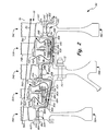
- FIG. 2 is an schematic cross-sectional side view of a turbine section of the gas turbine engine of FIG. 1 .
- FIG. 1 is a schematic cross-sectional side view of gas turbine engine 10.
- Gas turbine engine 10 includes low pressure spool 12 (which includes low pressure compressor 14 and low pressure turbine 16 connected by low pressure shaft 18), high pressure spool 20 (which includes high pressure compressor 22 and high pressure turbine 24 connected by high pressure shaft 26), combustor 28, nacelle 30, fan 32, fan shaft 34, and fan drive gear system 36 (which includes star gear 38, ring gear 40, and sun gear 42).
- low pressure spool 12 is coupled to fan shaft 34 via fan drive gear system 36.
- Sun gear 42 is attached to and rotates with low pressure shaft 18.
- Ring gear 40 is rigidly connected to fan shaft 34 which turns at the same speed as fan 32.
- Star gear 38 is coupled between sun gear 42 and ring gear 40 such that star gear 38 revolves around sun gear 42 when sun gear 42 rotates.
- fan drive gear system 36 causes fan shaft 34 to rotate at a slower rotational velocity than that of low pressure spool 12.
- fan 32 can be connected to low pressure spool 12 in a manner other than by fan drive gear system 36.
- gas turbine engine 10 can be a gas turbine engine of a different style and construction, such as an industrial turbine engine (not shown) or a gas turbine engine having fewer or more than two spools. The general construction and operation of gas turbine engines is well-known in the art, and therefore detailed discussion here is unnecessary.
- FIG. 2 is an schematic cross-sectional side view of turbine section 50, which includes stator stages 52A and 52B and rotor stages 54A-54C of low pressure turbine 16.
- Rotor stages 54A-54C each have sets of blades 56A-56C connected to rotor disks 58A-58C at blade attachments 60A-60C, respectively.
- Each set of blades 56A-56C extends from blade platforms 62A-62C, respectively.
- blade attachments 60A-60C are "fir tree" style attachments, with male connectors 64A-64C connected to blades 56A-56C, respectively, and female connectors 66A-66C connected to rotor disks 58A-58C, respectively.
- Male connectors 64A-64C slide into the serrated grooves of female connectors 66A-66C to attach blades 56A-56C to rotor disks 58A-58C, respectively.
- Rotor disk 58A connects to rotor disk 58B via arm 68A.
- Arm 68A is a rotor disk attachment arm integrally formed with rotor disk 58A and attached to rotor disk 58B via bolt 70 and nut 72.
- Rotor disk 58C connects to rotor disk 58B via arm 68C.
- Arm 68C is a disk attachment arm integrally formed with rotor disk 58C and attached to rotor disk 58B via bolt 70 and nut 72.
- Stator stages 52A and 52B include sets of stator vanes 74A and 74B extending from the radially outer side of vane platforms 76A and 76B, respectively.
- Honeycombs 78A and 78B extend from the radially inner side of vane platforms 76A and 76B, respectively.
- Rotor stage 54A is positioned substantially adjacent and upstream of stator stage 52A, which is positioned substantially adjacent and upstream of rotor stage 54B, which is positioned substantially adjacent and upstream of stator stage 52B, which is positioned substantially adjacent and upstream of rotor stage 54C.
- Cover plate 80A has upstream edge 82A adjacent a downstream side of blade platform 62A, downstream edge 84A adjacent an upstream side of blade platform 62B, and middle portion 85A in-between upstream edge 82A and downstream edge 84A. Thus, cover plate 80A extends from a downstream side of blade attachment 60A to an upstream side of blade attachment 60B. Cover plate 80A has knife edges 86A extending from middle portion 85A at radially outer surface 88A to contact honeycomb 78A. Knife edges 86A and honeycomb 78A combine to form labyrinth seal 90A.
- Cover plate 80A has radially inner surface 92A spaced from rotor disk 58A, arm 68A, and rotor disk 58B to define flow path 94A.
- Cover plate 80A is substantially ring shaped and can be formed of multiple segments as it extends circumferentially around turbine section 50.
- Cover plate 80A curves from its radially outer upstream edge 82A to its radially inner middle portion 85A to its radially outer downstream edge 84A.
- Cover plate 80B has upstream edge 82B adjacent a downstream side of blade platform 62B, downstream edge 84B adjacent an upstream side of blade platform 62C, and middle portion 85B in-between upstream edge 82B and downstream edge 84B. Thus, cover plate 80B extends from a downstream side of blade attachment 60B to an upstream side of blade attachment 60C. Cover plate 80B has knife edges 86B extending from middle portion 85B at radially outer surface 88B to contact honeycomb 78B. Knife edges 86B and honeycomb 78B combine to form labyrinth seal 90B.
- Cover plate 80B has radially inner surface 92B spaced from rotor disk 58B, ann 68B, and rotor disk 58C to define flow path 94B.
- Cover plate 80B is substantially ring shaped and can be formed of multiple segments as it extends circumferentially around turbine section 50.
- Cover plate 80B curves from its radially outer upstream edge 82B to its radially inner middle portion 85B to its radially outer downstream edge 84B.
- a gas such as air flows along main flow path 96, in a direction illustrated by arrow F1.
- Main flow path 96 extends from fan 32 (shown in FIG. 1 ), through low pressure compressor 14 (shown in FIG. 1 ), through high pressure compressor 22 (shown in FIG. 1 ), through combustor 28 (shown in FIG. 1 ), through high pressure turbine 24 (shown in FIG. 1 ), and through low pressure turbine 16.
- fan 32 shown in FIG. 1
- low pressure compressor 14 shown in FIG. 1
- high pressure compressor 22 shown in FIG. 1
- combustor 28 shown in FIG. 1
- high pressure turbine 24 shown in FIG. 1
- low pressure turbine 16 As gas flows through low pressure turbine 16, pressure drops as the gas flows downstream past each rotor stage 54A, 54B, and 54C and each stator stage 52A and 52B.
- Labyrinth seals 90A and 90B help to reduce such flow. However, such flow is not eliminated.
- Blade attachments 60A-60C typically experience high stress loads during operation, and consequently, it can be particularly important to reduce their exposure to excess heat.
- Cover plates 80A and 80B create a barrier to direct hot gas flow along flow arrows F2 and F3 back to main flow path 96. This reduces the amount of hot gas allowed to pass from main flow path 96 to and through blade attachments 60A-60C.
- relatively cool bleed air from low pressure compressor 14 and/or high pressure compressor 22 can be used to cool low pressure turbine 16 in general, and blade attachments 60A-60C in particular.
- Relatively cool bleed air can be directed through blade attachment 60A to flow path 94A.
- Flow path 94A directs that cool bleed air through blade attachment 60B to flow path 94B.
- Flow path 94B directs that cool bleed air through blade attachment 60C, and to subsequent stages, if any.
- cover plate 80C is shown, which would be positioned with respect to a subsequent stage (not shown).
- Flow paths 94A and 94B together join to form a combined flow path.
- cover plates 80A and 80B help direct cool bleed air through blade attachments 60A-60C (along flow arrows F4, F5, and F6) and reduce the amount of cool bleed air leaked to main flow path 96.
- Cover plates 80A and 80B substantially segregate flow paths 94A and 94B from main flow path 96. This allows for cooling to be performed using less bleed air, thus increasing efficiency of gas turbine engine 10 (shown in FIG. 1 ).
- the construction of cover plates 80A and 80B, combined with the construction of the rest of low pressure compressor 14, allow for this cooling to be performed while keeping overall weight relatively low.
- gas turbine engine 10 includes fan drive gear system 36 (shown in FIG. 1 ), low pressure spool 12 (and low pressure turbine 16) can rotate fast relative to fan 32. Such fast rotation can tend to increase the amount of hot gas flow along flow arrows F2 and F3.
- cover plates 80A and 80B and their corresponding flow paths 94A and 94B can be particularly useful in engines having a fan drive gear system such as fan drive gear system 36.
- cover plates 80A and 80B can also be particularly useful in other engines that benefit from cooling air flow, such as industrial gas turbine engines.
- stator stages 52A and 52B, rotor stages 54A-54C, and rotor disks 58A-58C can be constructed differently than precisely as illustrated.
Landscapes
- Engineering & Computer Science (AREA)
- Mechanical Engineering (AREA)
- General Engineering & Computer Science (AREA)
- Physics & Mathematics (AREA)
- Thermal Sciences (AREA)
- Structures Of Non-Positive Displacement Pumps (AREA)
- Turbine Rotor Nozzle Sealing (AREA)
Applications Claiming Priority (1)
| Application Number | Priority Date | Filing Date | Title |
|---|---|---|---|
| US13/194,261 US20130025290A1 (en) | 2011-07-29 | 2011-07-29 | Ingestion-tolerant low leakage low pressure turbine |
Publications (3)
| Publication Number | Publication Date |
|---|---|
| EP2551454A2 true EP2551454A2 (fr) | 2013-01-30 |
| EP2551454A3 EP2551454A3 (fr) | 2016-10-19 |
| EP2551454B1 EP2551454B1 (fr) | 2019-08-28 |
Family
ID=46639346
Family Applications (1)
| Application Number | Title | Priority Date | Filing Date |
|---|---|---|---|
| EP12178476.3A Active EP2551454B1 (fr) | 2011-07-29 | 2012-07-30 | Turbine basse pression à faible fuite |
Country Status (2)
| Country | Link |
|---|---|
| US (1) | US20130025290A1 (fr) |
| EP (1) | EP2551454B1 (fr) |
Cited By (3)
| Publication number | Priority date | Publication date | Assignee | Title |
|---|---|---|---|---|
| EP3208426A1 (fr) | 2016-02-18 | 2017-08-23 | MTU Aero Engines GmbH | Segment d'aube directrice pour turbomachine |
| EP3409897A1 (fr) | 2017-05-29 | 2018-12-05 | MTU Aero Engines GmbH | Agencement d'étanchéité pour une turbomachine, méthode de fabrication de l'agencement d'étanchéité et turbomachine |
| EP3483399A1 (fr) | 2017-11-09 | 2019-05-15 | MTU Aero Engines GmbH | Dispositif d'étanchéité pour une turbomachine, procédé de fabrication d'un dispositif d'étanchéité et turbomachine |
Families Citing this family (6)
| Publication number | Priority date | Publication date | Assignee | Title |
|---|---|---|---|---|
| US10578028B2 (en) | 2015-08-18 | 2020-03-03 | General Electric Company | Compressor bleed auxiliary turbine |
| US10711702B2 (en) | 2015-08-18 | 2020-07-14 | General Electric Company | Mixed flow turbocore |
| US10767485B2 (en) * | 2018-01-08 | 2020-09-08 | Raytheon Technologies Corporation | Radial cooling system for gas turbine engine compressors |
| FR3126141A1 (fr) * | 2021-08-11 | 2023-02-17 | Safran Aircraft Engines | Rotor de turbine a ventilation amelioree |
| US20240209782A1 (en) * | 2022-12-22 | 2024-06-27 | Raytheon Technologies Corporation | Electrically boosted turbine cooling air |
| DE102023117910A1 (de) | 2023-07-06 | 2025-01-09 | MTU Aero Engines AG | Modul für eine strömungsmaschine |
Family Cites Families (9)
| Publication number | Priority date | Publication date | Assignee | Title |
|---|---|---|---|---|
| US3056579A (en) * | 1959-04-13 | 1962-10-02 | Gen Electric | Rotor construction |
| GB2081392B (en) * | 1980-08-06 | 1983-09-21 | Rolls Royce | Turbomachine seal |
| FR2600377B1 (fr) * | 1986-06-18 | 1988-09-02 | Snecma | Dispositif de controle des debits d'air de refroidissement d'une turbine de moteur |
| US6464453B2 (en) * | 2000-12-04 | 2002-10-15 | General Electric Company | Turbine interstage sealing ring |
| FR2825748B1 (fr) * | 2001-06-07 | 2003-11-07 | Snecma Moteurs | Agencement de rotor de turbomachine a deux disques aubages separes par une entretoise |
| FR2857419B1 (fr) * | 2003-07-11 | 2005-09-23 | Snecma Moteurs | Liaison amelioree entre disques aubages sur la ligne rotor d'un compresseur |
| US8517666B2 (en) * | 2005-09-12 | 2013-08-27 | United Technologies Corporation | Turbine cooling air sealing |
| EP2039886B1 (fr) * | 2007-09-24 | 2010-06-23 | ALSTOM Technology Ltd | Soupape de retenue composite |
| US8381878B2 (en) * | 2009-11-12 | 2013-02-26 | United Technologies Corporation | Oil capture and bypass system |
-
2011
- 2011-07-29 US US13/194,261 patent/US20130025290A1/en not_active Abandoned
-
2012
- 2012-07-30 EP EP12178476.3A patent/EP2551454B1/fr active Active
Non-Patent Citations (1)
| Title |
|---|
| None |
Cited By (7)
| Publication number | Priority date | Publication date | Assignee | Title |
|---|---|---|---|---|
| EP3208426A1 (fr) | 2016-02-18 | 2017-08-23 | MTU Aero Engines GmbH | Segment d'aube directrice pour turbomachine |
| DE102016202519A1 (de) | 2016-02-18 | 2017-08-24 | MTU Aero Engines AG | Leitschaufelsegment für eine Strömungsmaschine |
| US10895162B2 (en) | 2016-02-18 | 2021-01-19 | MTU Aero Engines AG | Guide vane segment for a turbomachine |
| EP3409897A1 (fr) | 2017-05-29 | 2018-12-05 | MTU Aero Engines GmbH | Agencement d'étanchéité pour une turbomachine, méthode de fabrication de l'agencement d'étanchéité et turbomachine |
| US10808561B2 (en) | 2017-05-29 | 2020-10-20 | MTU Aero Engines AG | Seal arrangement for a turbomachine, method for manufacturing a seal arrangement and turbomachine |
| EP3483399A1 (fr) | 2017-11-09 | 2019-05-15 | MTU Aero Engines GmbH | Dispositif d'étanchéité pour une turbomachine, procédé de fabrication d'un dispositif d'étanchéité et turbomachine |
| US10865651B2 (en) | 2017-11-09 | 2020-12-15 | MTU Aero Engines AG | Sealing assembly for a fluid kinetic machine, method for producing a sealing assembly as well as fluid kinetic machine |
Also Published As
| Publication number | Publication date |
|---|---|
| EP2551454B1 (fr) | 2019-08-28 |
| EP2551454A3 (fr) | 2016-10-19 |
| US20130025290A1 (en) | 2013-01-31 |
Similar Documents
| Publication | Publication Date | Title |
|---|---|---|
| EP2551454B1 (fr) | Turbine basse pression à faible fuite | |
| EP2978938B1 (fr) | Agencement de turbine avec une languette d'étanchéité en forme de l | |
| EP3044416B1 (fr) | Elément de profil d'aube avec des groupes de trous de refroidissement du type pommeau de douche | |
| US10947853B2 (en) | Gas turbine component with platform cooling | |
| EP3054138B1 (fr) | Turbocompresseur avec turboréacteur à double flux à engrenage | |
| US20180230839A1 (en) | Turbine engine shroud assembly | |
| US10738693B2 (en) | Advanced gas turbine engine | |
| EP3012405B1 (fr) | Turbine à gaz avec composant de réorientation d'un flux de réfrigérant | |
| EP2551458A2 (fr) | Système d'étanchéité et de refroidissement d'aube | |
| EP2971568B1 (fr) | Joint plat pour une soufflante d'un moteur à turbine à gaz | |
| US12037942B2 (en) | Efficient aircraft engine | |
| EP2458155A3 (fr) | Turbine à gaz à flux axial | |
| US20220307448A1 (en) | Efficient gas turbine engine | |
| EP3822459B1 (fr) | Virole d'étanchéité avec rainure de refroidissement | |
| US12110830B2 (en) | Gas turbine engine | |
| EP3159503B1 (fr) | Agencement de prélèvement d'air d'un compresseur d'une turbine à gaz et méthode de fabrication d'une section de compresseur de turbine à gaz | |
| US11466617B2 (en) | Gas turbine engine with efficient thrust generation | |
| EP3000966B1 (fr) | Procédé et ensemble permettant de réduire la chaleur secondaire dans un moteur à turbine à gaz | |
| US20200049067A1 (en) | Aircraft engine with high propulsive and thermal efficiency | |
| US20160369816A1 (en) | Tandem rotor blades with cooling features | |
| US20170089210A1 (en) | Seal arrangement for compressor or turbine section of gas turbine engine | |
| EP3392472B1 (fr) | Section de compresseur pour un moteur à turbine à gaz, moteur à turbine à gaz et procédé de fonctionnement d'une section de compresseur dans un moteur à turbine à gaz, associés |
Legal Events
| Date | Code | Title | Description |
|---|---|---|---|
| PUAI | Public reference made under article 153(3) epc to a published international application that has entered the european phase |
Free format text: ORIGINAL CODE: 0009012 |
|
| AK | Designated contracting states |
Kind code of ref document: A2 Designated state(s): AL AT BE BG CH CY CZ DE DK EE ES FI FR GB GR HR HU IE IS IT LI LT LU LV MC MK MT NL NO PL PT RO RS SE SI SK SM TR |
|
| AX | Request for extension of the european patent |
Extension state: BA ME |
|
| PUAL | Search report despatched |
Free format text: ORIGINAL CODE: 0009013 |
|
| AK | Designated contracting states |
Kind code of ref document: A3 Designated state(s): AL AT BE BG CH CY CZ DE DK EE ES FI FR GB GR HR HU IE IS IT LI LT LU LV MC MK MT NL NO PL PT RO RS SE SI SK SM TR |
|
| AX | Request for extension of the european patent |
Extension state: BA ME |
|
| RIC1 | Information provided on ipc code assigned before grant |
Ipc: F01D 11/00 20060101ALI20160909BHEP Ipc: F01D 5/08 20060101AFI20160909BHEP |
|
| RAP1 | Party data changed (applicant data changed or rights of an application transferred) |
Owner name: UNITED TECHNOLOGIES CORPORATION |
|
| STAA | Information on the status of an ep patent application or granted ep patent |
Free format text: STATUS: REQUEST FOR EXAMINATION WAS MADE |
|
| 17P | Request for examination filed |
Effective date: 20170418 |
|
| RBV | Designated contracting states (corrected) |
Designated state(s): AL AT BE BG CH CY CZ DE DK EE ES FI FR GB GR HR HU IE IS IT LI LT LU LV MC MK MT NL NO PL PT RO RS SE SI SK SM TR |
|
| STAA | Information on the status of an ep patent application or granted ep patent |
Free format text: STATUS: EXAMINATION IS IN PROGRESS |
|
| 17Q | First examination report despatched |
Effective date: 20180420 |
|
| GRAP | Despatch of communication of intention to grant a patent |
Free format text: ORIGINAL CODE: EPIDOSNIGR1 |
|
| STAA | Information on the status of an ep patent application or granted ep patent |
Free format text: STATUS: GRANT OF PATENT IS INTENDED |
|
| INTG | Intention to grant announced |
Effective date: 20190219 |
|
| GRAS | Grant fee paid |
Free format text: ORIGINAL CODE: EPIDOSNIGR3 |
|
| GRAA | (expected) grant |
Free format text: ORIGINAL CODE: 0009210 |
|
| STAA | Information on the status of an ep patent application or granted ep patent |
Free format text: STATUS: THE PATENT HAS BEEN GRANTED |
|
| AK | Designated contracting states |
Kind code of ref document: B1 Designated state(s): AL AT BE BG CH CY CZ DE DK EE ES FI FR GB GR HR HU IE IS IT LI LT LU LV MC MK MT NL NO PL PT RO RS SE SI SK SM TR |
|
| REG | Reference to a national code |
Ref country code: GB Ref legal event code: FG4D |
|
| REG | Reference to a national code |
Ref country code: CH Ref legal event code: EP |
|
| REG | Reference to a national code |
Ref country code: AT Ref legal event code: REF Ref document number: 1172640 Country of ref document: AT Kind code of ref document: T Effective date: 20190915 |
|
| REG | Reference to a national code |
Ref country code: IE Ref legal event code: FG4D |
|
| REG | Reference to a national code |
Ref country code: DE Ref legal event code: R096 Ref document number: 602012063319 Country of ref document: DE |
|
| REG | Reference to a national code |
Ref country code: NL Ref legal event code: MP Effective date: 20190828 |
|
| REG | Reference to a national code |
Ref country code: LT Ref legal event code: MG4D |
|
| PG25 | Lapsed in a contracting state [announced via postgrant information from national office to epo] |
Ref country code: HR Free format text: LAPSE BECAUSE OF FAILURE TO SUBMIT A TRANSLATION OF THE DESCRIPTION OR TO PAY THE FEE WITHIN THE PRESCRIBED TIME-LIMIT Effective date: 20190828 Ref country code: LT Free format text: LAPSE BECAUSE OF FAILURE TO SUBMIT A TRANSLATION OF THE DESCRIPTION OR TO PAY THE FEE WITHIN THE PRESCRIBED TIME-LIMIT Effective date: 20190828 Ref country code: BG Free format text: LAPSE BECAUSE OF FAILURE TO SUBMIT A TRANSLATION OF THE DESCRIPTION OR TO PAY THE FEE WITHIN THE PRESCRIBED TIME-LIMIT Effective date: 20191128 Ref country code: SE Free format text: LAPSE BECAUSE OF FAILURE TO SUBMIT A TRANSLATION OF THE DESCRIPTION OR TO PAY THE FEE WITHIN THE PRESCRIBED TIME-LIMIT Effective date: 20190828 Ref country code: NL Free format text: LAPSE BECAUSE OF FAILURE TO SUBMIT A TRANSLATION OF THE DESCRIPTION OR TO PAY THE FEE WITHIN THE PRESCRIBED TIME-LIMIT Effective date: 20190828 Ref country code: FI Free format text: LAPSE BECAUSE OF FAILURE TO SUBMIT A TRANSLATION OF THE DESCRIPTION OR TO PAY THE FEE WITHIN THE PRESCRIBED TIME-LIMIT Effective date: 20190828 Ref country code: PT Free format text: LAPSE BECAUSE OF FAILURE TO SUBMIT A TRANSLATION OF THE DESCRIPTION OR TO PAY THE FEE WITHIN THE PRESCRIBED TIME-LIMIT Effective date: 20191230 Ref country code: NO Free format text: LAPSE BECAUSE OF FAILURE TO SUBMIT A TRANSLATION OF THE DESCRIPTION OR TO PAY THE FEE WITHIN THE PRESCRIBED TIME-LIMIT Effective date: 20191128 |
|
| PG25 | Lapsed in a contracting state [announced via postgrant information from national office to epo] |
Ref country code: IS Free format text: LAPSE BECAUSE OF FAILURE TO SUBMIT A TRANSLATION OF THE DESCRIPTION OR TO PAY THE FEE WITHIN THE PRESCRIBED TIME-LIMIT Effective date: 20191228 Ref country code: RS Free format text: LAPSE BECAUSE OF FAILURE TO SUBMIT A TRANSLATION OF THE DESCRIPTION OR TO PAY THE FEE WITHIN THE PRESCRIBED TIME-LIMIT Effective date: 20190828 Ref country code: LV Free format text: LAPSE BECAUSE OF FAILURE TO SUBMIT A TRANSLATION OF THE DESCRIPTION OR TO PAY THE FEE WITHIN THE PRESCRIBED TIME-LIMIT Effective date: 20190828 Ref country code: AL Free format text: LAPSE BECAUSE OF FAILURE TO SUBMIT A TRANSLATION OF THE DESCRIPTION OR TO PAY THE FEE WITHIN THE PRESCRIBED TIME-LIMIT Effective date: 20190828 Ref country code: GR Free format text: LAPSE BECAUSE OF FAILURE TO SUBMIT A TRANSLATION OF THE DESCRIPTION OR TO PAY THE FEE WITHIN THE PRESCRIBED TIME-LIMIT Effective date: 20191129 Ref country code: ES Free format text: LAPSE BECAUSE OF FAILURE TO SUBMIT A TRANSLATION OF THE DESCRIPTION OR TO PAY THE FEE WITHIN THE PRESCRIBED TIME-LIMIT Effective date: 20190828 |
|
| REG | Reference to a national code |
Ref country code: AT Ref legal event code: MK05 Ref document number: 1172640 Country of ref document: AT Kind code of ref document: T Effective date: 20190828 |
|
| PG25 | Lapsed in a contracting state [announced via postgrant information from national office to epo] |
Ref country code: TR Free format text: LAPSE BECAUSE OF FAILURE TO SUBMIT A TRANSLATION OF THE DESCRIPTION OR TO PAY THE FEE WITHIN THE PRESCRIBED TIME-LIMIT Effective date: 20190828 |
|
| PG25 | Lapsed in a contracting state [announced via postgrant information from national office to epo] |
Ref country code: AT Free format text: LAPSE BECAUSE OF FAILURE TO SUBMIT A TRANSLATION OF THE DESCRIPTION OR TO PAY THE FEE WITHIN THE PRESCRIBED TIME-LIMIT Effective date: 20190828 Ref country code: DK Free format text: LAPSE BECAUSE OF FAILURE TO SUBMIT A TRANSLATION OF THE DESCRIPTION OR TO PAY THE FEE WITHIN THE PRESCRIBED TIME-LIMIT Effective date: 20190828 Ref country code: PL Free format text: LAPSE BECAUSE OF FAILURE TO SUBMIT A TRANSLATION OF THE DESCRIPTION OR TO PAY THE FEE WITHIN THE PRESCRIBED TIME-LIMIT Effective date: 20190828 Ref country code: IT Free format text: LAPSE BECAUSE OF FAILURE TO SUBMIT A TRANSLATION OF THE DESCRIPTION OR TO PAY THE FEE WITHIN THE PRESCRIBED TIME-LIMIT Effective date: 20190828 Ref country code: RO Free format text: LAPSE BECAUSE OF FAILURE TO SUBMIT A TRANSLATION OF THE DESCRIPTION OR TO PAY THE FEE WITHIN THE PRESCRIBED TIME-LIMIT Effective date: 20190828 Ref country code: EE Free format text: LAPSE BECAUSE OF FAILURE TO SUBMIT A TRANSLATION OF THE DESCRIPTION OR TO PAY THE FEE WITHIN THE PRESCRIBED TIME-LIMIT Effective date: 20190828 |
|
| PG25 | Lapsed in a contracting state [announced via postgrant information from national office to epo] |
Ref country code: SM Free format text: LAPSE BECAUSE OF FAILURE TO SUBMIT A TRANSLATION OF THE DESCRIPTION OR TO PAY THE FEE WITHIN THE PRESCRIBED TIME-LIMIT Effective date: 20190828 Ref country code: CZ Free format text: LAPSE BECAUSE OF FAILURE TO SUBMIT A TRANSLATION OF THE DESCRIPTION OR TO PAY THE FEE WITHIN THE PRESCRIBED TIME-LIMIT Effective date: 20190828 Ref country code: SK Free format text: LAPSE BECAUSE OF FAILURE TO SUBMIT A TRANSLATION OF THE DESCRIPTION OR TO PAY THE FEE WITHIN THE PRESCRIBED TIME-LIMIT Effective date: 20190828 Ref country code: IS Free format text: LAPSE BECAUSE OF FAILURE TO SUBMIT A TRANSLATION OF THE DESCRIPTION OR TO PAY THE FEE WITHIN THE PRESCRIBED TIME-LIMIT Effective date: 20200224 |
|
| REG | Reference to a national code |
Ref country code: DE Ref legal event code: R097 Ref document number: 602012063319 Country of ref document: DE |
|
| PLBE | No opposition filed within time limit |
Free format text: ORIGINAL CODE: 0009261 |
|
| STAA | Information on the status of an ep patent application or granted ep patent |
Free format text: STATUS: NO OPPOSITION FILED WITHIN TIME LIMIT |
|
| PG2D | Information on lapse in contracting state deleted |
Ref country code: IS |
|
| 26N | No opposition filed |
Effective date: 20200603 |
|
| PG25 | Lapsed in a contracting state [announced via postgrant information from national office to epo] |
Ref country code: SI Free format text: LAPSE BECAUSE OF FAILURE TO SUBMIT A TRANSLATION OF THE DESCRIPTION OR TO PAY THE FEE WITHIN THE PRESCRIBED TIME-LIMIT Effective date: 20190828 |
|
| PG25 | Lapsed in a contracting state [announced via postgrant information from national office to epo] |
Ref country code: MC Free format text: LAPSE BECAUSE OF FAILURE TO SUBMIT A TRANSLATION OF THE DESCRIPTION OR TO PAY THE FEE WITHIN THE PRESCRIBED TIME-LIMIT Effective date: 20190828 |
|
| REG | Reference to a national code |
Ref country code: CH Ref legal event code: PL |
|
| REG | Reference to a national code |
Ref country code: BE Ref legal event code: MM Effective date: 20200731 |
|
| PG25 | Lapsed in a contracting state [announced via postgrant information from national office to epo] |
Ref country code: LU Free format text: LAPSE BECAUSE OF NON-PAYMENT OF DUE FEES Effective date: 20200730 Ref country code: CH Free format text: LAPSE BECAUSE OF NON-PAYMENT OF DUE FEES Effective date: 20200731 Ref country code: LI Free format text: LAPSE BECAUSE OF NON-PAYMENT OF DUE FEES Effective date: 20200731 |
|
| PG25 | Lapsed in a contracting state [announced via postgrant information from national office to epo] |
Ref country code: BE Free format text: LAPSE BECAUSE OF NON-PAYMENT OF DUE FEES Effective date: 20200731 |
|
| PG25 | Lapsed in a contracting state [announced via postgrant information from national office to epo] |
Ref country code: IE Free format text: LAPSE BECAUSE OF NON-PAYMENT OF DUE FEES Effective date: 20200730 |
|
| PG25 | Lapsed in a contracting state [announced via postgrant information from national office to epo] |
Ref country code: MT Free format text: LAPSE BECAUSE OF FAILURE TO SUBMIT A TRANSLATION OF THE DESCRIPTION OR TO PAY THE FEE WITHIN THE PRESCRIBED TIME-LIMIT Effective date: 20190828 Ref country code: CY Free format text: LAPSE BECAUSE OF FAILURE TO SUBMIT A TRANSLATION OF THE DESCRIPTION OR TO PAY THE FEE WITHIN THE PRESCRIBED TIME-LIMIT Effective date: 20190828 |
|
| PG25 | Lapsed in a contracting state [announced via postgrant information from national office to epo] |
Ref country code: MK Free format text: LAPSE BECAUSE OF FAILURE TO SUBMIT A TRANSLATION OF THE DESCRIPTION OR TO PAY THE FEE WITHIN THE PRESCRIBED TIME-LIMIT Effective date: 20190828 |
|
| REG | Reference to a national code |
Ref country code: DE Ref legal event code: R081 Ref document number: 602012063319 Country of ref document: DE Owner name: RAYTHEON TECHNOLOGIES CORPORATION (N.D.GES.D.S, US Free format text: FORMER OWNER: UNITED TECHNOLOGIES CORPORATION, FARMINGTON, CONN., US |
|
| P01 | Opt-out of the competence of the unified patent court (upc) registered |
Effective date: 20230520 |
|
| PGFP | Annual fee paid to national office [announced via postgrant information from national office to epo] |
Ref country code: GB Payment date: 20240620 Year of fee payment: 13 |
|
| PGFP | Annual fee paid to national office [announced via postgrant information from national office to epo] |
Ref country code: FR Payment date: 20240619 Year of fee payment: 13 |
|
| PGFP | Annual fee paid to national office [announced via postgrant information from national office to epo] |
Ref country code: DE Payment date: 20240619 Year of fee payment: 13 |
|
| REG | Reference to a national code |
Ref country code: DE Ref legal event code: R119 Ref document number: 602012063319 Country of ref document: DE |
|
| GBPC | Gb: european patent ceased through non-payment of renewal fee |
Effective date: 20250730 |
|
| PG25 | Lapsed in a contracting state [announced via postgrant information from national office to epo] |
Ref country code: GB Free format text: LAPSE BECAUSE OF NON-PAYMENT OF DUE FEES Effective date: 20250730 |
|
| PG25 | Lapsed in a contracting state [announced via postgrant information from national office to epo] |
Ref country code: DE Free format text: LAPSE BECAUSE OF NON-PAYMENT OF DUE FEES Effective date: 20260203 |
|
| PG25 | Lapsed in a contracting state [announced via postgrant information from national office to epo] |
Ref country code: FR Free format text: LAPSE BECAUSE OF NON-PAYMENT OF DUE FEES Effective date: 20250731 |