EP3208426A1 - Segment d'aube directrice pour turbomachine - Google Patents
Segment d'aube directrice pour turbomachine Download PDFInfo
- Publication number
- EP3208426A1 EP3208426A1 EP16203029.0A EP16203029A EP3208426A1 EP 3208426 A1 EP3208426 A1 EP 3208426A1 EP 16203029 A EP16203029 A EP 16203029A EP 3208426 A1 EP3208426 A1 EP 3208426A1
- Authority
- EP
- European Patent Office
- Prior art keywords
- flange
- vane
- positioning means
- seal carrier
- support surface
- Prior art date
- Legal status (The legal status is an assumption and is not a legal conclusion. Google has not performed a legal analysis and makes no representation as to the accuracy of the status listed.)
- Granted
Links
Images

Classifications
-
- F—MECHANICAL ENGINEERING; LIGHTING; HEATING; WEAPONS; BLASTING
- F01—MACHINES OR ENGINES IN GENERAL; ENGINE PLANTS IN GENERAL; STEAM ENGINES
- F01D—NON-POSITIVE DISPLACEMENT MACHINES OR ENGINES, e.g. STEAM TURBINES
- F01D9/00—Stators
- F01D9/02—Nozzles; Nozzle boxes; Stator blades; Guide conduits, e.g. individual nozzles
- F01D9/04—Nozzles; Nozzle boxes; Stator blades; Guide conduits, e.g. individual nozzles forming ring or sector
-
- F—MECHANICAL ENGINEERING; LIGHTING; HEATING; WEAPONS; BLASTING
- F01—MACHINES OR ENGINES IN GENERAL; ENGINE PLANTS IN GENERAL; STEAM ENGINES
- F01D—NON-POSITIVE DISPLACEMENT MACHINES OR ENGINES, e.g. STEAM TURBINES
- F01D9/00—Stators
- F01D9/02—Nozzles; Nozzle boxes; Stator blades; Guide conduits, e.g. individual nozzles
- F01D9/04—Nozzles; Nozzle boxes; Stator blades; Guide conduits, e.g. individual nozzles forming ring or sector
- F01D9/041—Nozzles; Nozzle boxes; Stator blades; Guide conduits, e.g. individual nozzles forming ring or sector using blades
-
- F—MECHANICAL ENGINEERING; LIGHTING; HEATING; WEAPONS; BLASTING
- F01—MACHINES OR ENGINES IN GENERAL; ENGINE PLANTS IN GENERAL; STEAM ENGINES
- F01D—NON-POSITIVE DISPLACEMENT MACHINES OR ENGINES, e.g. STEAM TURBINES
- F01D11/00—Preventing or minimising internal leakage of working-fluid, e.g. between stages
- F01D11/001—Preventing or minimising internal leakage of working-fluid, e.g. between stages for sealing space between stator blade and rotor
-
- F—MECHANICAL ENGINEERING; LIGHTING; HEATING; WEAPONS; BLASTING
- F01—MACHINES OR ENGINES IN GENERAL; ENGINE PLANTS IN GENERAL; STEAM ENGINES
- F01D—NON-POSITIVE DISPLACEMENT MACHINES OR ENGINES, e.g. STEAM TURBINES
- F01D11/00—Preventing or minimising internal leakage of working-fluid, e.g. between stages
- F01D11/003—Preventing or minimising internal leakage of working-fluid, e.g. between stages by packing rings; Mechanical seals
-
- F—MECHANICAL ENGINEERING; LIGHTING; HEATING; WEAPONS; BLASTING
- F01—MACHINES OR ENGINES IN GENERAL; ENGINE PLANTS IN GENERAL; STEAM ENGINES
- F01D—NON-POSITIVE DISPLACEMENT MACHINES OR ENGINES, e.g. STEAM TURBINES
- F01D11/00—Preventing or minimising internal leakage of working-fluid, e.g. between stages
- F01D11/005—Sealing means between non relatively rotating elements
-
- F—MECHANICAL ENGINEERING; LIGHTING; HEATING; WEAPONS; BLASTING
- F01—MACHINES OR ENGINES IN GENERAL; ENGINE PLANTS IN GENERAL; STEAM ENGINES
- F01D—NON-POSITIVE DISPLACEMENT MACHINES OR ENGINES, e.g. STEAM TURBINES
- F01D25/00—Component parts, details, or accessories, not provided for in, or of interest apart from, other groups
- F01D25/24—Casings; Casing parts, e.g. diaphragms, casing fastenings
- F01D25/243—Flange connections; Bolting arrangements
-
- F—MECHANICAL ENGINEERING; LIGHTING; HEATING; WEAPONS; BLASTING
- F01—MACHINES OR ENGINES IN GENERAL; ENGINE PLANTS IN GENERAL; STEAM ENGINES
- F01D—NON-POSITIVE DISPLACEMENT MACHINES OR ENGINES, e.g. STEAM TURBINES
- F01D9/00—Stators
- F01D9/02—Nozzles; Nozzle boxes; Stator blades; Guide conduits, e.g. individual nozzles
- F01D9/04—Nozzles; Nozzle boxes; Stator blades; Guide conduits, e.g. individual nozzles forming ring or sector
- F01D9/042—Nozzles; Nozzle boxes; Stator blades; Guide conduits, e.g. individual nozzles forming ring or sector fixing blades to stators
-
- F—MECHANICAL ENGINEERING; LIGHTING; HEATING; WEAPONS; BLASTING
- F05—INDEXING SCHEMES RELATING TO ENGINES OR PUMPS IN VARIOUS SUBCLASSES OF CLASSES F01-F04
- F05D—INDEXING SCHEME FOR ASPECTS RELATING TO NON-POSITIVE-DISPLACEMENT MACHINES OR ENGINES, GAS-TURBINES OR JET-PROPULSION PLANTS
- F05D2220/00—Application
- F05D2220/30—Application in turbines
- F05D2220/32—Application in turbines in gas turbines
- F05D2220/323—Application in turbines in gas turbines for aircraft propulsion, e.g. jet engines
-
- F—MECHANICAL ENGINEERING; LIGHTING; HEATING; WEAPONS; BLASTING
- F05—INDEXING SCHEMES RELATING TO ENGINES OR PUMPS IN VARIOUS SUBCLASSES OF CLASSES F01-F04
- F05D—INDEXING SCHEME FOR ASPECTS RELATING TO NON-POSITIVE-DISPLACEMENT MACHINES OR ENGINES, GAS-TURBINES OR JET-PROPULSION PLANTS
- F05D2240/00—Components
- F05D2240/10—Stators
- F05D2240/12—Fluid guiding means, e.g. vanes
-
- F—MECHANICAL ENGINEERING; LIGHTING; HEATING; WEAPONS; BLASTING
- F05—INDEXING SCHEMES RELATING TO ENGINES OR PUMPS IN VARIOUS SUBCLASSES OF CLASSES F01-F04
- F05D—INDEXING SCHEME FOR ASPECTS RELATING TO NON-POSITIVE-DISPLACEMENT MACHINES OR ENGINES, GAS-TURBINES OR JET-PROPULSION PLANTS
- F05D2240/00—Components
- F05D2240/55—Seals
Definitions
- the invention relates to a stator blade segment for a turbomachine, in particular for an aircraft engine. Further aspects of the invention relate to a vane element for such a vane segment, a vane ring with at least one vane segment and a turbomachine.
- a gas turbine stage which has a sealing ring element mounted on a guide blade root by means of a spoke centering.
- This spoke centering has an inner wall and a peripheral groove receiving it.
- the inner wall has a, a Nutinnen derivative the circumferential groove facing end face and one of these adjacent, against this angled edge. Between the end face and the flank a rounding is formed as a radius. If, during the intended use of the gas turbine stage, a system of the front face, which is in the direction of flow, on the groove inner surface, this radius reduces the stress load and the wear.
- the EP 2 722 486 A1 shows a fishmouth seal carrier for a guide vane assembly of a gas turbine.
- the fishmouth seal carrier has a box profile with two axial legs and two radial legs and a sealing element, which is arranged on one of the axial leg on.
- An integrally formed axial flange for forming a fish mouth seal is provided on the box profile.
- a low-pressure turbine which has a plurality of stator stages. At respective radial ends of the stator stages honeycomb structures are arranged to form a seal with low fluid leakage with radially opposite these labyrinth seals on a shaft housing.
- the object of the present invention is to improve a vane segment, a vane element, a vane ring, and a turbomachine of the type mentioned above, so that these components have a high tightness against fluid leakage even under heavy use.
- a partial surface of the positioning means abuts against the flange, and respective surface normals of the support surface and the partial surface coincide with each other at an angle other than a zero angle.
- the transition from the flange to the positioning means may, for example, be in the form of a straight line or a curved line on which the flange and the face can adjoin one another.
- the transition can also be formed as an edge, for example with an edge rounding, on which the flange and the partial surface adjoin one another.
- the inclusion of an angle other than a zero angle through the respective surface normals of the support surface and the partial surface is accompanied by the fact that the partial surface can be offset at least in regions relative to the support surface. Accordingly, in the intended use of the guide blade segment as a component of a turbomachine, the partial surface can be recessed in a main flow direction of a working fluid flowing through the latter during operation of the turbomachine with respect to the support surface.
- the partial surface may, for example, run bevelled at least in regions relative to the support surface. Additionally or alternatively, the partial surface and the support surface may also form at least a portion of a shoulder on the flange.
- the support surface can be configured as a sealing surface that rotates radially on the flange, against which the partial surface can be set back and additionally or alternatively beveled.
- SIAS Static Inner Air Seal
- the vane segment may correspond to a part of a vane ring, and may be formed, for example, as a vane ring segment. Accordingly, the vane segment can be designed, for example, as a third and thus as a 120 ° segment of such a vane ring.
- the vane segment may include, for example, a radially inner shroud segment, a vane blade or a plurality of vane blades, as well as a radially outer shroud segment, in addition to the flange and the positioning means.
- the seal carrier can have a sealing element, for example in the form of a brush seal or a honeycomb seal, at a radial end.
- the support surface may be formed as a sealing surface to reduce fluid leakage between the flange and the seal carrier.
- the positioning means may engage, for example, in a circumferential radial groove of the seal carrier.
- the seal carrier may further be fixed to the flange and thus to the vane element by means of a fixing element, which may be formed, for example, as a bolt.
- the support surface is formed at least substantially as an annular surface segment. This allows a particularly uniform surface pressure be achieved between the seal carrier and the support surface. This has the advantage that a uniform sealing effect on the support surface can be achieved even with dynamic loads of the seal carrier.
- the positioning means is integrally connected to the flange.
- the seal carrier has at least one circumferential radial groove with which the positioning means in the arrangement of the seal carrier on the flange is engaged. This is advantageous because the groove allows the flange and the positioning means to engage around the flange at least in some areas when the seal carrier is arranged. As a result, any degrees of freedom of movement between the seal carrier and the vane element are restricted in a simple manner.
- the positioning means at least two forked positioning mandrels, which engage in the arrangement of the seal carrier on the flange in the circumferential radial groove.
- the fork-shaped arrangement of the positioning mandrels can also be referred to as spoke centering. Due to the fork-shaped configuration, any rotation of the seal carrier about the two positioning mandrels can be prevented. Thus, a further degree of freedom of movement of the seal carrier can be restricted in a simple manner.
- a second aspect of the invention relates to a vane member for a vane segment according to the invention, comprising a flange formed in a radial direction of extension of the vane member having a support surface for locating and supporting a seal carrier, and at least one positioning member projecting from the flange in the radial direction of extent the seal carrier relative to the vane element.
- a partial surface of the positioning means adjoins the flange and respective surface normals of the support surface and the sub-area include an angle different from a zero angle with each other.
- a third aspect of the invention relates to a vane ring comprising at least one vane segment according to the invention.
- the vane ring may for example be composed of three 120 ° vane segments. Such a vane ring contributes in an improved way to reducing fluid leakage.
- a fourth aspect of the invention relates to a turbomachine, in particular an aircraft engine, with at least one guide vane segment according to the invention and additionally or alternatively with at least one guide vane element according to the invention and additionally or alternatively with at least one vane ring.
- a turbomachine can be operated under a reduced fluid leakage and thus at a particularly high efficiency.
- the turbomachine is a turbine and the support surface of the flange faces a main flow direction of a working fluid flowing through the latter during operation of the turbomachine.
- the turbomachine is a compressor and the support surface of the flange faces away from a main flow direction of a working medium flowing through the latter during operation of the turbomachine.
- Fig. 1 shows a known from the prior art vane segment 50, for a turbomachine.
- the vane segment 50 has a sealing area 52 on a flat sealing surface 54 to which a radial seal not shown here can be brought into abutment.
- the vane segment 50 has a serrated centering 56 for the radial seal.
- the sealing surface 54 extends in the present case over a particularly large, in Fig. 1 hatched area, which also includes a partial surface area of individual centering elements of the serrated centering 56.
- the installation 57 extends over two fork-shaped centering struts 58 of the centering 56.
- the installation 57 can also be referred to as a support location on an edge region of the sealing surface 54.
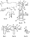
- a vane element 12 is shown, which in Fig. 2b in a side view according to a in Fig. 2a illustrated by an arrow view direction A together with a seal carrier 30 is shown.
- the vane element 12 and the seal carrier 30 belong to one in Fig. 2b partial illustrated guide vane segment 10 for a turbomachine not shown here, which may be formed, for example, as an aircraft engine.
- the vane segment 10 thus comprises the vane element 12 and the seal carrier 30.
- a guide vane ring, not shown here, can be composed of a plurality of such vane segments 10 and used in the turbomachine.
- the vane element 12 comprises at least one airfoil 36, a radially inner shroud segment 34, and a radially outer shroud segment (not shown further here).
- the two shroud segments connect to on opposite sides of the at least one airfoil 36 to this.
- the vane element 12 comprises a flange 14 formed in a radial extension direction R of the vane element 12 and at least one positioning means 18 protruding from the flange 14 in the radial direction of extension R.
- the positioning means 18 is in one piece connected to the flange 14.
- the vane segment is in Fig. 2b pushed along a mounting direction M on the present annular seal carrier 30, so that the seal carrier 30 and the flange 14 abut each other.
- the flange 14 has a support surface 16 on which the seal carrier 30 is supported in its abutment with the flange 14.
- the Supporting surface 16 of the flange 14 faces a main flow direction H of a working medium flowing through it during operation of the turbomachine, provided that the turbomachine is configured as a turbine.
- the support surface 16 of the flange 14 would be remote from the main flow direction H.
- the support surface 16 serves as a sealing surface with which the seal carrier 30 in its arrangement and support on the flange 14 forms a sealing seat.
- the support surface 16 is formed at least substantially as an annular surface segment.
- the "at least substantially training as an annular surface segment” is to be understood that the support surface 16 is designed predominantly as an annular surface segment, but may deviate in areas of an annular shape by the support surface is limited in regions instead of by means of a circular arc, for example by means of a straight line.
- the support surface 16 in the radial direction of extension R can also be limited by a transition 19 formed, for example, as a straight line and accordingly has no circumferential radial rounding at such a boundary point and deviates slightly from a ring segment shape.
- a partial surface 20 of the positioning means 18 adjoins the flange 14, wherein respective surface normals 17, 21 of the support surface 16 and the partial surface 20 form an angle ⁇ different from a zero angle.
- the first surface normal 17 is assigned to the support surface 16, whereas the second surface normal 21 is assigned to the surface 20.
- the seal carrier 30 in the present case has a circumferential radial groove 32, with which the positioning means 18 in the arrangement of the seal carrier 30 on the flange 14 is engaged.
- a sealing element 31 designed, for example, as a brush seal or honeycomb seal is arranged.
- the seal carrier 30 can be fixed to the flange 14 as soon as the seal carrier 30 is brought into abutment with the support surface 16.
- the positioning means 18 in the present case has two fork-shaped positioning mandrels 22, 24, which in the arrangement of the seal carrier 30 on the flange 14 engage in the circumferential radial groove 32.
- the bolt 28 can be performed for fixing the seal carrier 30 by one of the two positioning mandrels 22, 24 partially limited recess 26.
- the positioning mandrels 22, 24 may each be referred to as "Tang".
- FIG. 2b In the Fig. 2b, Fig. 3 and Fig. 4a In each case different embodiments of the vane element 12 are shown. In these figures, only the first positioning mandrel 22 is shown as representative of both positioning mandrels 22, 24, which conceals the second positioning mandrel 24 in these figures.
- the partial surface 20 of the positioning mandrel 22 and thus of the positioning means 18 directly adjoins the transition 19.
- the surface normals 17, 21 include the angle ⁇ , which may also be referred to as the so-called "tang angle”.
- the embodiment according to Fig. 3 a curved course of the partial surface 20 and thus a curvature of the partial surface 20.
- the seal carrier 30 can rest flat on the support surface 16, without coming into contact with the part surface 20 and thus the positioning means 18.
- an arrangement of the seal carrier 30 on the support surface 16 can be ensured under a large surface pressure and thus under a particularly good sealing effect.
- the vane element 12 may have a shoulder, which in Fig. 4b is shown enlarged according to a detailed view B. The shoulder extends over an adjacent to the support surface 16 flange 15 of the flange 14th
- a radial position of a vertex of the angle ⁇ can - as in Fig. 2b shown - lie on the transition 19, wherein the partial surface 20 beveled relative to the support surface 16 to this followed.
- the angle ⁇ can also, as in Fig. 3 shown to change over the course of the surface 20. Due to the fact that the surface normals 17, 21 of the support surface 16 or of the sub-surface 20 enclose the angle ⁇ different from the zero angle, an offset results between the support surface 16 and the sub-surface 20 in the main flow direction H. This offset enables operational deformations of the bearing SIAS (seal carrier 30) can be allowed without it comes with these deformations to a lifting of the seal carrier 30 of the support surface 16.
- protrusions includes such elements which protrude radially inwardly (in the radial direction of extension R) with respect to the support surface 16 (sealing surface on the flange 14).
- protrusions includes anti-rotation or sprues.
Landscapes
- Engineering & Computer Science (AREA)
- Mechanical Engineering (AREA)
- General Engineering & Computer Science (AREA)
- Structures Of Non-Positive Displacement Pumps (AREA)
- Turbine Rotor Nozzle Sealing (AREA)
Applications Claiming Priority (1)
| Application Number | Priority Date | Filing Date | Title |
|---|---|---|---|
| DE102016202519.8A DE102016202519A1 (de) | 2016-02-18 | 2016-02-18 | Leitschaufelsegment für eine Strömungsmaschine |
Publications (2)
| Publication Number | Publication Date |
|---|---|
| EP3208426A1 true EP3208426A1 (fr) | 2017-08-23 |
| EP3208426B1 EP3208426B1 (fr) | 2025-04-30 |
Family
ID=57530609
Family Applications (1)
| Application Number | Title | Priority Date | Filing Date |
|---|---|---|---|
| EP16203029.0A Active EP3208426B1 (fr) | 2016-02-18 | 2016-12-08 | Segment d'aube directrice pour turbomachine |
Country Status (4)
| Country | Link |
|---|---|
| US (1) | US10895162B2 (fr) |
| EP (1) | EP3208426B1 (fr) |
| DE (1) | DE102016202519A1 (fr) |
| ES (1) | ES3032768T3 (fr) |
Families Citing this family (4)
| Publication number | Priority date | Publication date | Assignee | Title |
|---|---|---|---|---|
| DE102017221660A1 (de) * | 2017-12-01 | 2019-06-06 | MTU Aero Engines AG | Modul für eine Strömungsmaschine |
| DE102020200073A1 (de) * | 2020-01-07 | 2021-07-08 | Siemens Aktiengesellschaft | Leitschaufelkranz |
| DE102020203840A1 (de) | 2020-03-25 | 2021-09-30 | MTU Aero Engines AG | Gasturbinenbauteil |
| DE102020115106B4 (de) | 2020-06-08 | 2022-08-25 | Man Energy Solutions Se | Turbinenleitapparat |
Citations (7)
| Publication number | Priority date | Publication date | Assignee | Title |
|---|---|---|---|---|
| US4194869A (en) | 1978-06-29 | 1980-03-25 | United Technologies Corporation | Stator vane cluster |
| EP2551454A2 (fr) | 2011-07-29 | 2013-01-30 | United Technologies Corporation | Turbine basse pression à faible fuite |
| EP2559849A2 (fr) * | 2011-08-16 | 2013-02-20 | United Technologies Corporation | Ensemble joint de moteur à turbine à gaz ayant un tube à passage de flux |
| FR2979662A1 (fr) * | 2011-09-07 | 2013-03-08 | Snecma | Procede de fabrication d'un secteur de distributeur de turbine ou redresseur de compresseur en materiau composite pour turbomachine et turbine ou compresseur incorporant un distributeur ou un redresseur forme de tels secteurs |
| EP2696039A1 (fr) | 2012-08-10 | 2014-02-12 | MTU Aero Engines GmbH | Étage de turbine à gaz |
| EP2722486A1 (fr) | 2012-10-17 | 2014-04-23 | MTU Aero Engines GmbH | Support d'étanchéité pour ensemble statorique |
| EP2811117A2 (fr) * | 2013-06-05 | 2014-12-10 | Rolls-Royce Deutschland Ltd & Co KG | Anneau de renforcement pour une turbomachine |
Family Cites Families (19)
| Publication number | Priority date | Publication date | Assignee | Title |
|---|---|---|---|---|
| US3829233A (en) * | 1973-06-27 | 1974-08-13 | Westinghouse Electric Corp | Turbine diaphragm seal structure |
| US4286921A (en) * | 1979-12-13 | 1981-09-01 | Westinghouse Electric Corp. | Locking structure for an alignment bushing of a combustion turbine engine |
| US4863343A (en) * | 1988-05-16 | 1989-09-05 | Westinghouse Electric Corp. | Turbine vane shroud sealing system |
| US4890978A (en) * | 1988-10-19 | 1990-01-02 | Westinghouse Electric Corp. | Method and apparatus for vane segment support and alignment in combustion turbines |
| US5224822A (en) * | 1991-05-13 | 1993-07-06 | General Electric Company | Integral turbine nozzle support and discourager seal |
| US5215435A (en) * | 1991-10-28 | 1993-06-01 | General Electric Company | Angled cooling air bypass slots in honeycomb seals |
| JP2961089B2 (ja) * | 1997-06-05 | 1999-10-12 | 三菱重工業株式会社 | ガスタービン1段静翼シール構造 |
| US6637751B2 (en) * | 2001-12-28 | 2003-10-28 | General Electric Company | Supplemental seal for the chordal hinge seals in a gas turbine |
| US7160078B2 (en) * | 2004-09-23 | 2007-01-09 | General Electric Company | Mechanical solution for rail retention of turbine nozzles |
| DE102005059084A1 (de) * | 2005-12-10 | 2007-06-14 | Mtu Aero Engines Gmbh | Turbomaschine, insbesondere Gasturbine |
| US8070427B2 (en) * | 2007-10-31 | 2011-12-06 | General Electric Company | Gas turbines having flexible chordal hinge seals |
| FR2935428B1 (fr) * | 2008-08-26 | 2015-06-26 | Snecma | Aubage fixe de turbomachine a masse reduite et turbomachine comportant au moins un tel aubage fixe |
| EP2383435A1 (fr) * | 2010-04-29 | 2011-11-02 | Siemens Aktiengesellschaft | Rail interne creux d'aube de turbine |
| JP6271582B2 (ja) * | 2012-12-29 | 2018-01-31 | ユナイテッド テクノロジーズ コーポレイションUnited Technologies Corporation | ガスタービンシールアセンブリおよびシール支持体 |
| EP2938836B1 (fr) * | 2012-12-29 | 2020-02-05 | United Technologies Corporation | Disque et ensemble de support d'étanchéité |
| US10094389B2 (en) * | 2012-12-29 | 2018-10-09 | United Technologies Corporation | Flow diverter to redirect secondary flow |
| EP2762684B1 (fr) * | 2013-01-30 | 2021-03-03 | MTU Aero Engines AG | Support d'étanchéité à base d'aluminure de titane pour une turbomachine |
| FR3011271B1 (fr) * | 2013-10-01 | 2018-01-19 | Safran Aircraft Engines | Dispositif de connexion d'une partie fixe de turbomachine et d'un pied de distributeur d'une turbine de turbomachine |
| DE102015224378A1 (de) * | 2015-12-04 | 2017-06-08 | MTU Aero Engines AG | Leitschaufelsegment mit Radialsicherung |
-
2016
- 2016-02-18 DE DE102016202519.8A patent/DE102016202519A1/de not_active Ceased
- 2016-12-08 EP EP16203029.0A patent/EP3208426B1/fr active Active
- 2016-12-08 ES ES16203029T patent/ES3032768T3/es active Active
-
2017
- 2017-02-09 US US15/428,386 patent/US10895162B2/en active Active
Patent Citations (7)
| Publication number | Priority date | Publication date | Assignee | Title |
|---|---|---|---|---|
| US4194869A (en) | 1978-06-29 | 1980-03-25 | United Technologies Corporation | Stator vane cluster |
| EP2551454A2 (fr) | 2011-07-29 | 2013-01-30 | United Technologies Corporation | Turbine basse pression à faible fuite |
| EP2559849A2 (fr) * | 2011-08-16 | 2013-02-20 | United Technologies Corporation | Ensemble joint de moteur à turbine à gaz ayant un tube à passage de flux |
| FR2979662A1 (fr) * | 2011-09-07 | 2013-03-08 | Snecma | Procede de fabrication d'un secteur de distributeur de turbine ou redresseur de compresseur en materiau composite pour turbomachine et turbine ou compresseur incorporant un distributeur ou un redresseur forme de tels secteurs |
| EP2696039A1 (fr) | 2012-08-10 | 2014-02-12 | MTU Aero Engines GmbH | Étage de turbine à gaz |
| EP2722486A1 (fr) | 2012-10-17 | 2014-04-23 | MTU Aero Engines GmbH | Support d'étanchéité pour ensemble statorique |
| EP2811117A2 (fr) * | 2013-06-05 | 2014-12-10 | Rolls-Royce Deutschland Ltd & Co KG | Anneau de renforcement pour une turbomachine |
Also Published As
| Publication number | Publication date |
|---|---|
| US20170241279A1 (en) | 2017-08-24 |
| US10895162B2 (en) | 2021-01-19 |
| EP3208426B1 (fr) | 2025-04-30 |
| ES3032768T3 (en) | 2025-07-24 |
| DE102016202519A1 (de) | 2017-08-24 |
Similar Documents
| Publication | Publication Date | Title |
|---|---|---|
| DE102005045459B4 (de) | Mechanische Lösung zur Schienenhalterung von Turbinendüsen | |
| EP1148209B1 (fr) | Configuration de joint inter-étages | |
| EP3409897B1 (fr) | Agencement d'étanchéité pour une turbomachine, méthode de fabrication de l'agencement d'étanchéité et turbomachine | |
| EP1694943B1 (fr) | Turbomachine | |
| DE112013006128T5 (de) | Laufschaufel und zugehöriges Herstellungsverfahren | |
| EP2728122B1 (fr) | Fixation de support d'étanchéité pour turbomachine | |
| DE112016004554T5 (de) | Betätigungsvorrichtung für variable Statorschaufeln | |
| EP3208426B1 (fr) | Segment d'aube directrice pour turbomachine | |
| EP2884054A1 (fr) | Aube de guidage variable avec cône tronqué dans un ensemble palier | |
| EP3287611A1 (fr) | Turbine à gaz et procédé de suspension d'un segment d'aube de guidage d'une turbine à gaz | |
| DE102012008723A1 (de) | Leitrad für Turbomaschinen und Herstellungsverfahren | |
| EP3409899A1 (fr) | Dispositif de joint d'étanchéité pourvu de tôle d'étanchéité assemblée par soudage, turbomachine et procédé de fabrication | |
| EP3287608B1 (fr) | Bague intérieure d'une couronne d'aubes directrices d'une turbomachine | |
| DE102016201766A1 (de) | Leitschaufelsystem für eine Strömungsmaschine | |
| DE102009007664A1 (de) | Abdichtvorrichtung an dem Schaufelschaft einer Rotorstufe einer axialen Strömungsmaschine | |
| DE69709563T2 (de) | Turbomaschinenschaufeldichtung | |
| EP2405104A1 (fr) | Compresseur et moteur à turbine à gaz associé | |
| EP3176386B1 (fr) | Système de virole interne, virole interne, boîtier intermédiaire et turbomachine associés | |
| EP2811117A2 (fr) | Anneau de renforcement pour une turbomachine | |
| EP3875736B1 (fr) | Dispositif d'étanchéité pour une turbomachine, bague de support pour un dispositif d'étanchéité et turbomachine | |
| EP1653049B1 (fr) | Couronne d'aubes directrices pour turbines à gaz et procédé pour sa modification | |
| EP3309359B1 (fr) | Ensemble d'aubes mobiles pour un moteur à turbine à gaz | |
| EP3628030A1 (fr) | Procédé d'entretien d'une turbomachine | |
| DE102021129534A1 (de) | Leitschaufelanordnung einer Strömungsmaschine und Verfahren zur Montage einer Leitschaufelanordnung | |
| DE102021109844A1 (de) | Gasturbinen-Schaufelanordnung |
Legal Events
| Date | Code | Title | Description |
|---|---|---|---|
| PUAI | Public reference made under article 153(3) epc to a published international application that has entered the european phase |
Free format text: ORIGINAL CODE: 0009012 |
|
| STAA | Information on the status of an ep patent application or granted ep patent |
Free format text: STATUS: THE APPLICATION HAS BEEN PUBLISHED |
|
| AK | Designated contracting states |
Kind code of ref document: A1 Designated state(s): AL AT BE BG CH CY CZ DE DK EE ES FI FR GB GR HR HU IE IS IT LI LT LU LV MC MK MT NL NO PL PT RO RS SE SI SK SM TR |
|
| AX | Request for extension of the european patent |
Extension state: BA ME |
|
| STAA | Information on the status of an ep patent application or granted ep patent |
Free format text: STATUS: REQUEST FOR EXAMINATION WAS MADE |
|
| 17P | Request for examination filed |
Effective date: 20180219 |
|
| RBV | Designated contracting states (corrected) |
Designated state(s): AL AT BE BG CH CY CZ DE DK EE ES FI FR GB GR HR HU IE IS IT LI LT LU LV MC MK MT NL NO PL PT RO RS SE SI SK SM TR |
|
| STAA | Information on the status of an ep patent application or granted ep patent |
Free format text: STATUS: EXAMINATION IS IN PROGRESS |
|
| 17Q | First examination report despatched |
Effective date: 20190725 |
|
| GRAP | Despatch of communication of intention to grant a patent |
Free format text: ORIGINAL CODE: EPIDOSNIGR1 |
|
| STAA | Information on the status of an ep patent application or granted ep patent |
Free format text: STATUS: GRANT OF PATENT IS INTENDED |
|
| INTG | Intention to grant announced |
Effective date: 20241212 |
|
| GRAS | Grant fee paid |
Free format text: ORIGINAL CODE: EPIDOSNIGR3 |
|
| GRAA | (expected) grant |
Free format text: ORIGINAL CODE: 0009210 |
|
| STAA | Information on the status of an ep patent application or granted ep patent |
Free format text: STATUS: THE PATENT HAS BEEN GRANTED |
|
| AK | Designated contracting states |
Kind code of ref document: B1 Designated state(s): AL AT BE BG CH CY CZ DE DK EE ES FI FR GB GR HR HU IE IS IT LI LT LU LV MC MK MT NL NO PL PT RO RS SE SI SK SM TR |
|
| REG | Reference to a national code |
Ref country code: CH Ref legal event code: EP Ref country code: GB Ref legal event code: FG4D Free format text: NOT ENGLISH |
|
| REG | Reference to a national code |
Ref country code: DE Ref legal event code: R096 Ref document number: 502016016965 Country of ref document: DE |
|
| REG | Reference to a national code |
Ref country code: IE Ref legal event code: FG4D Free format text: LANGUAGE OF EP DOCUMENT: GERMAN |
|
| REG | Reference to a national code |
Ref country code: ES Ref legal event code: FG2A Ref document number: 3032768 Country of ref document: ES Kind code of ref document: T3 Effective date: 20250724 |
|
| REG | Reference to a national code |
Ref country code: NL Ref legal event code: MP Effective date: 20250430 |
|
| PG25 | Lapsed in a contracting state [announced via postgrant information from national office to epo] |
Ref country code: PT Free format text: LAPSE BECAUSE OF FAILURE TO SUBMIT A TRANSLATION OF THE DESCRIPTION OR TO PAY THE FEE WITHIN THE PRESCRIBED TIME-LIMIT Effective date: 20250901 Ref country code: FI Free format text: LAPSE BECAUSE OF FAILURE TO SUBMIT A TRANSLATION OF THE DESCRIPTION OR TO PAY THE FEE WITHIN THE PRESCRIBED TIME-LIMIT Effective date: 20250430 |
|
| REG | Reference to a national code |
Ref country code: LT Ref legal event code: MG9D |
|
| PG25 | Lapsed in a contracting state [announced via postgrant information from national office to epo] |
Ref country code: NO Free format text: LAPSE BECAUSE OF FAILURE TO SUBMIT A TRANSLATION OF THE DESCRIPTION OR TO PAY THE FEE WITHIN THE PRESCRIBED TIME-LIMIT Effective date: 20250730 Ref country code: GR Free format text: LAPSE BECAUSE OF FAILURE TO SUBMIT A TRANSLATION OF THE DESCRIPTION OR TO PAY THE FEE WITHIN THE PRESCRIBED TIME-LIMIT Effective date: 20250731 |
|
| PG25 | Lapsed in a contracting state [announced via postgrant information from national office to epo] |
Ref country code: PL Free format text: LAPSE BECAUSE OF FAILURE TO SUBMIT A TRANSLATION OF THE DESCRIPTION OR TO PAY THE FEE WITHIN THE PRESCRIBED TIME-LIMIT Effective date: 20250430 Ref country code: NL Free format text: LAPSE BECAUSE OF FAILURE TO SUBMIT A TRANSLATION OF THE DESCRIPTION OR TO PAY THE FEE WITHIN THE PRESCRIBED TIME-LIMIT Effective date: 20250430 |
|
| PG25 | Lapsed in a contracting state [announced via postgrant information from national office to epo] |
Ref country code: BG Free format text: LAPSE BECAUSE OF FAILURE TO SUBMIT A TRANSLATION OF THE DESCRIPTION OR TO PAY THE FEE WITHIN THE PRESCRIBED TIME-LIMIT Effective date: 20250430 |
|
| PG25 | Lapsed in a contracting state [announced via postgrant information from national office to epo] |
Ref country code: HR Free format text: LAPSE BECAUSE OF FAILURE TO SUBMIT A TRANSLATION OF THE DESCRIPTION OR TO PAY THE FEE WITHIN THE PRESCRIBED TIME-LIMIT Effective date: 20250430 |
|
| PG25 | Lapsed in a contracting state [announced via postgrant information from national office to epo] |
Ref country code: RS Free format text: LAPSE BECAUSE OF FAILURE TO SUBMIT A TRANSLATION OF THE DESCRIPTION OR TO PAY THE FEE WITHIN THE PRESCRIBED TIME-LIMIT Effective date: 20250731 |
|
| PG25 | Lapsed in a contracting state [announced via postgrant information from national office to epo] |
Ref country code: IS Free format text: LAPSE BECAUSE OF FAILURE TO SUBMIT A TRANSLATION OF THE DESCRIPTION OR TO PAY THE FEE WITHIN THE PRESCRIBED TIME-LIMIT Effective date: 20250830 |
|
| PG25 | Lapsed in a contracting state [announced via postgrant information from national office to epo] |
Ref country code: LV Free format text: LAPSE BECAUSE OF FAILURE TO SUBMIT A TRANSLATION OF THE DESCRIPTION OR TO PAY THE FEE WITHIN THE PRESCRIBED TIME-LIMIT Effective date: 20250430 |
|
| PGFP | Annual fee paid to national office [announced via postgrant information from national office to epo] |
Ref country code: GB Payment date: 20251218 Year of fee payment: 10 |
|
| PG25 | Lapsed in a contracting state [announced via postgrant information from national office to epo] |
Ref country code: SM Free format text: LAPSE BECAUSE OF FAILURE TO SUBMIT A TRANSLATION OF THE DESCRIPTION OR TO PAY THE FEE WITHIN THE PRESCRIBED TIME-LIMIT Effective date: 20250430 Ref country code: DK Free format text: LAPSE BECAUSE OF FAILURE TO SUBMIT A TRANSLATION OF THE DESCRIPTION OR TO PAY THE FEE WITHIN THE PRESCRIBED TIME-LIMIT Effective date: 20250430 |
|
| PGFP | Annual fee paid to national office [announced via postgrant information from national office to epo] |
Ref country code: FR Payment date: 20251217 Year of fee payment: 10 |
|
| PG25 | Lapsed in a contracting state [announced via postgrant information from national office to epo] |
Ref country code: CZ Free format text: LAPSE BECAUSE OF FAILURE TO SUBMIT A TRANSLATION OF THE DESCRIPTION OR TO PAY THE FEE WITHIN THE PRESCRIBED TIME-LIMIT Effective date: 20250430 |
|
| PG25 | Lapsed in a contracting state [announced via postgrant information from national office to epo] |
Ref country code: EE Free format text: LAPSE BECAUSE OF FAILURE TO SUBMIT A TRANSLATION OF THE DESCRIPTION OR TO PAY THE FEE WITHIN THE PRESCRIBED TIME-LIMIT Effective date: 20250430 |
|
| PG25 | Lapsed in a contracting state [announced via postgrant information from national office to epo] |
Ref country code: RO Free format text: LAPSE BECAUSE OF FAILURE TO SUBMIT A TRANSLATION OF THE DESCRIPTION OR TO PAY THE FEE WITHIN THE PRESCRIBED TIME-LIMIT Effective date: 20250430 Ref country code: SK Free format text: LAPSE BECAUSE OF FAILURE TO SUBMIT A TRANSLATION OF THE DESCRIPTION OR TO PAY THE FEE WITHIN THE PRESCRIBED TIME-LIMIT Effective date: 20250430 |
|
| PG25 | Lapsed in a contracting state [announced via postgrant information from national office to epo] |
Ref country code: IT Free format text: LAPSE BECAUSE OF FAILURE TO SUBMIT A TRANSLATION OF THE DESCRIPTION OR TO PAY THE FEE WITHIN THE PRESCRIBED TIME-LIMIT Effective date: 20250430 |
|
| REG | Reference to a national code |
Ref country code: DE Ref legal event code: R097 Ref document number: 502016016965 Country of ref document: DE |
|
| PLBE | No opposition filed within time limit |
Free format text: ORIGINAL CODE: 0009261 |
|
| STAA | Information on the status of an ep patent application or granted ep patent |
Free format text: STATUS: NO OPPOSITION FILED WITHIN TIME LIMIT |
|
| REG | Reference to a national code |
Ref country code: CH Ref legal event code: L10 Free format text: ST27 STATUS EVENT CODE: U-0-0-L10-L00 (AS PROVIDED BY THE NATIONAL OFFICE) Effective date: 20260311 |
|
| 26N | No opposition filed |
Effective date: 20260202 |
|
| PGFP | Annual fee paid to national office [announced via postgrant information from national office to epo] |
Ref country code: ES Payment date: 20260119 Year of fee payment: 10 |
|
| PGFP | Annual fee paid to national office [announced via postgrant information from national office to epo] |
Ref country code: DE Payment date: 20251222 Year of fee payment: 10 |