EP2551494A2 - Motor-Generator und Getriebebaugruppe eine Antriebsmaschine - Google Patents
Motor-Generator und Getriebebaugruppe eine Antriebsmaschine Download PDFInfo
- Publication number
- EP2551494A2 EP2551494A2 EP12178472A EP12178472A EP2551494A2 EP 2551494 A2 EP2551494 A2 EP 2551494A2 EP 12178472 A EP12178472 A EP 12178472A EP 12178472 A EP12178472 A EP 12178472A EP 2551494 A2 EP2551494 A2 EP 2551494A2
- Authority
- EP
- European Patent Office
- Prior art keywords
- mechanical transmission
- motor
- generator
- prime mover
- rotational speed
- Prior art date
- Legal status (The legal status is an assumption and is not a legal conclusion. Google has not performed a legal analysis and makes no representation as to the accuracy of the status listed.)
- Granted
Links
Images

Classifications
-
- F—MECHANICAL ENGINEERING; LIGHTING; HEATING; WEAPONS; BLASTING
- F02—COMBUSTION ENGINES; HOT-GAS OR COMBUSTION-PRODUCT ENGINE PLANTS
- F02C—GAS-TURBINE PLANTS; AIR INTAKES FOR JET-PROPULSION PLANTS; CONTROLLING FUEL SUPPLY IN AIR-BREATHING JET-PROPULSION PLANTS
- F02C7/00—Features, components parts, details or accessories, not provided for in, or of interest apart form groups F02C1/00 - F02C6/00; Air intakes for jet-propulsion plants
- F02C7/36—Power transmission arrangements between the different shafts of the gas turbine plant, or between the gas-turbine plant and the power user
-
- Y—GENERAL TAGGING OF NEW TECHNOLOGICAL DEVELOPMENTS; GENERAL TAGGING OF CROSS-SECTIONAL TECHNOLOGIES SPANNING OVER SEVERAL SECTIONS OF THE IPC; TECHNICAL SUBJECTS COVERED BY FORMER USPC CROSS-REFERENCE ART COLLECTIONS [XRACs] AND DIGESTS
- Y10—TECHNICAL SUBJECTS COVERED BY FORMER USPC
- Y10T—TECHNICAL SUBJECTS COVERED BY FORMER US CLASSIFICATION
- Y10T74/00—Machine element or mechanism
- Y10T74/19—Gearing
-
- Y—GENERAL TAGGING OF NEW TECHNOLOGICAL DEVELOPMENTS; GENERAL TAGGING OF CROSS-SECTIONAL TECHNOLOGIES SPANNING OVER SEVERAL SECTIONS OF THE IPC; TECHNICAL SUBJECTS COVERED BY FORMER USPC CROSS-REFERENCE ART COLLECTIONS [XRACs] AND DIGESTS
- Y10—TECHNICAL SUBJECTS COVERED BY FORMER USPC
- Y10T—TECHNICAL SUBJECTS COVERED BY FORMER US CLASSIFICATION
- Y10T74/00—Machine element or mechanism
- Y10T74/19—Gearing
- Y10T74/19005—Nonplanetary gearing differential type [e.g., gearless differentials]
-
- Y—GENERAL TAGGING OF NEW TECHNOLOGICAL DEVELOPMENTS; GENERAL TAGGING OF CROSS-SECTIONAL TECHNOLOGIES SPANNING OVER SEVERAL SECTIONS OF THE IPC; TECHNICAL SUBJECTS COVERED BY FORMER USPC CROSS-REFERENCE ART COLLECTIONS [XRACs] AND DIGESTS
- Y10—TECHNICAL SUBJECTS COVERED BY FORMER USPC
- Y10T—TECHNICAL SUBJECTS COVERED BY FORMER US CLASSIFICATION
- Y10T74/00—Machine element or mechanism
- Y10T74/19—Gearing
- Y10T74/19009—Single gearing unit includes fluid drive
-
- Y—GENERAL TAGGING OF NEW TECHNOLOGICAL DEVELOPMENTS; GENERAL TAGGING OF CROSS-SECTIONAL TECHNOLOGIES SPANNING OVER SEVERAL SECTIONS OF THE IPC; TECHNICAL SUBJECTS COVERED BY FORMER USPC CROSS-REFERENCE ART COLLECTIONS [XRACs] AND DIGESTS
- Y10—TECHNICAL SUBJECTS COVERED BY FORMER USPC
- Y10T—TECHNICAL SUBJECTS COVERED BY FORMER US CLASSIFICATION
- Y10T74/00—Machine element or mechanism
- Y10T74/19—Gearing
- Y10T74/19149—Gearing with fluid drive
- Y10T74/19158—Gearing with fluid drive with one or more controllers for gearing, fluid drive, or clutch
- Y10T74/19163—Gearing with fluid drive with one or more controllers for gearing, fluid drive, or clutch with interrelated controls
Definitions
- This disclosure relates generally to a gearing assembly that rotatably couples a prime mover and a motor-generator.
- Prime movers such as turbomachines
- a typical turbomachine includes a fan section, a compression section, a combustor section, and a turbine section.
- Turbomachines have at least one rotor in the compression section. The rotor must be accelerated to a relatively high rotational speed until the rotor is rotating fast enough to sustain operation of the turbomachine.
- a motor-generator separate from the turbomachine, is used as a motor to rotate the rotor during start-up of the turbomachine. After the turbomachine is self-sustaining, the motor-generator is used as a generator and driven by the turbomachine.
- the rotational speeds of prime movers may be different than the optimal speed of the motor-generator. Also, the rotational speeds vary considerably during operation, and it is desirable to provide the motor-generator with a rotational input that is relatively consistent. Hydro-mechanical transmissions are thus used to step-up or step-down rotation between the prime mover and the motor-generator. The size and weight of the hydro-mechanical transmissions must increase to accommodate larger ranges of rotational speeds.
- An example mechanical transmission assembly receives an input rotating at a first rotational speed and provides an output rotating at a second rotational speed.
- the mechanical transmission selectively adjusts the second rotational speed.
- the input is provided by a prime mover.
- the output is provided to a hydraulic pump assembly that rotatably drives a motor-generator.
- An example prime mover gearing arrangement includes a hydro-mechanical transmission having a differential assembly and a hydraulic pump.
- a motor-generator is rotatably driven by the hydro-mechanical transmission.
- a mechanical transmission is rotatably driven by the prime mover at a first rotational speed. The mechanical transmission selectively adjusts to rotatably drive the hydraulic pump at the first rotational speed or a second rotational speed different than the first rotational speed.
- An example method of driving a motor-generator with a prime mover includes driving a mechanical transmission with an input shaft from a prime mover.
- the input shaft rotates at a first rotational speed.
- the method drives a hydraulic pump with a first output shaft from the mechanical transmission.
- the first output shaft rotates at a second rotational speed.
- the method drives the motor-generator with the hydraulic pump.
- the method selectively adjusts the mechanical transmission so that the first rotational speed is different than the second rotational speed.
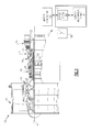
- an example gas turbine engine 10 is used to propel an aircraft.
- the gas turbine engine 10 is an example type of turbomachine, which is an example type of prime mover.
- the gas turbine engine 10 is circumferentially disposed about an axis X.
- the gas turbine engine 10 includes a fan section 14, a low-pressure compressor section 16, a high-pressure compressor section 18, a combustion section 20, a high-pressure turbine section 22, and a low-pressure turbine section 24.
- Other example turbomachines may include more or fewer sections.
- the low-pressure compressor section 16 includes a rotor 26.
- the high-pressure compressor section 18 includes a rotor 28.
- the example rotors 26 and 28 include alternating rows of rotating airfoils or rotating blades and static airfoils or static blades.
- the high-pressure turbine section 22 includes a rotor 30.
- the low-pressure turbine section 24 includes a rotor 32.
- the rotors 30 and 32 are configured to rotate about the axis X in response to expansion across the high-pressure turbine section 22 and the low-pressure turbine section 24.
- the example rotors 30 and 32 include alternating rows of rotatable airfoils or rotatable blades and static airfoils or static blades.
- the rotor 30 is coupled to the rotor 28 through a high-pressure spool 34.
- the rotor 32 is coupled to the rotor 26 through a low-pressure spool 36.
- rotation of the rotors 30 and 32 rotates the rotors 28 and 26, which drives compression in the high-pressure compressor section 18 and the low-pressure compressor section 16, respectively.
- the low-pressure spool 36 rotates across a greater range of rotational speeds than the high-pressure spool 34.
- a prime mover in this disclosure are described with reference to the gas turbine engine 10 that has a two-spool architecture, the examples are not limited to such architectures. That is, other types of turbomachines, and gas turbine engines having other architectures, such as a single-spool axial design, a three-spool axial design, may be used, as well as other prime movers, such as a piston engine, wankel engine, etc. There are various arrangements having prime movers that could benefit from the examples disclosed herein.
- the low-pressure spool 36 drives a motor-generator 50 when the motor-generator 50 is operating in a generator mode.
- the low-pressure spool 36 may drive the motor-generator 50 instead of, or in addition to, the high-pressure spool 34.
- the motor-generator 50 provides electrical power to various loads on the aircraft.
- the motor-generator 50 is typically required to provide power at a relatively constant frequency, or to ensure that the delivered power varies within a range of frequencies, such as 360-800 Hertz.
- the rotational speed of the low-pressure spool 36 varies considerably during operation of the gas turbine engine 10.
- the range of potential rotational speeds for the low-pressure spool 36 is greater than the range of potential speeds for the high-pressure spool 34.
- a gearing arrangement 52 accommodates the variation in rotational speeds from the low-pressure spool 36 and rotatably drives the motor-generator 50.
- the high-pressure spool 34 is typically used to drive the motor-generator 50.
- the example gearing arrangement 52 includes a hydro-mechanical transmission 54 and a mechanical transmission 56 separate from the hydro-mechanical transmission 54.
- the hydro-mechanical transmission 54 is constantly variable and includes a hydraulic pump 58 and a differential 66.
- the mechanical transmission 56 is configured to be selectively adjusted between a first position and a second position. In the first position, the mechanical transmission 56 rotates the differential 66 at the same speed as the low-pressure spool 36. In the second position, the mechanical transmission 56 rotates the differential 66 faster than the low-pressure spool 36.
- the example mechanical transmission 56 is a two-speed transmission. In other examples, the mechanical transmission 56 may adjust between three-speeds, or even more speeds.
- the differential 66 when the mechanical transmission 56 is in the first position, the differential 66 is rotated at 4,000 rpm when the low-pressure spool 36 rotates at 2,000 rpm. In this specific example, when the mechanical transmission 56 is in the second position, the differential 66 rotates at 4,000 rpm when the low-pressure spool 36 rotates at 4,000 rpm.
- the hydraulic pump 58 may further adjust the rotational speed. The hydraulic pump 58 rotates the motor-generator 50 through the differential 66.
- the example mechanical transmission 56 receives a rotational input from the low-pressure spool 36 through an input 70, which is an input shaft in this example.
- the rotational speed of the input 70 can vary during operation of the gas turbine engine 10 between a high speed that is five times greater than a low speed.
- the input 70 may rotate at 5,000 rpm at a high end and 1,000 rpm at a low end.
- the input 70 is directly engaged with the mechanical transmission 56 in this example.
- the mechanical transmission 56 then provides a rotational output via an output 72, which is also directly engaged with the mechanical transmission 56.
- the output 72 is a differential ring gear in this example.
- the example mechanical transmission 56 moves from a position where the output 72 rotates at the same speed as the input 70, and another position where the output 72 rotates twice for every single rotation of the input 70.
- the example mechanical transmission 56 includes a sunless differential gearing arrangement.
- the example mechanical transmission 56 is similar in design to the differential 66.
- a person having skill in this art and the benefit of this disclosure would understand how to design other types of mechanical transmissions movable between a position where the input and output rotate at the same speed, and a second position where the output rotates twice as fast as the input.
- the mechanical transmission 56 is connected to a controller 74.
- the controller 74 initiates movement of the mechanical transmission 56 between the first position and the second position depending on the rotational speed of the low-pressure spool 36.
- the controller 74 may monitor the rotational speed of the low-pressure spool 36 to determine when to initiate movement between the first position and the second position.
- the controller 74 may automatically initiate movement, or may require a manual input, such as a switch.
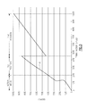
- the controller 74 may maintain the mechanical transmission 56 in the first position as the rotational speed of the low-pressure spool 36 increases from about 20% to 45% of the total potential speed of the low-pressure spool 36 along a path 78.
- 20% of the total potential speed is about 2,000 rpm and 45% of the total potential speed is about 4,000 rpm.
- the controller 74 moves the mechanical transmission 56 to the second position where the input 70 rotates together with the output 72.
- Other examples may move the mechanical transmission to a third position.
- the output 72 rotates the differential 66, which then provides a rotational input to the hydraulic pump 58.
- the hydraulic pump 58 further adjusts the rotational speeds to ensure that the motor-generator 50 provides a relatively consistent output.
- the hydraulic pump 58 rotatably drives the motor-generator 50 through the differential 66.
- the hydraulic pump 58 always receives an input that is greater than 4,000 rpm, even when the low-pressure spool 36 is rotating at a speed slower than 4,000 rpm.
- the mechanical transmission 56 ensures that the rotational speed from the differential 66 is maintained above 4,000 rpm.
- the hydraulic pump 58 receives an input rotating at 4,000 rpm or less.
- the input speed is optimized for the hydraulic pump 58.
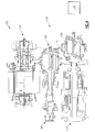
- another example gearing arrangement 152 includes a mechanical transmission 156, a differential 166, and a hydraulic pump 158.
- the numbering used in Figure 4 corresponds to the numbering in Figure 3 with a preappended "1."
- an input 170 is provided to the mechanical transmission by the differential 166.
- the differential 166 is rotated by a shaft 80 coupled to the low-pressure spool 36.
- the mechanical transmission 156 then is selectively moved between two positions to rotate the hydraulic pump 158 at the desired speed.
- a controller 174 may be used to control the movement of the mechanical transmission 156 between the first position and the second position.
- An output 172 in this example, is an output shaft extending directly from the mechanical transmission 156 to the hydraulic pump 158.
- the output 172 rotates the mechanical transmission 156.
- the hydraulic pump 158 then rotates the motor-generator 150 through the differential 166.
- gearing arrangement capable of receiving an input from a low-pressure spool of a turbomachine and providing rotational input to a motor-generator.
Landscapes
- Engineering & Computer Science (AREA)
- Chemical & Material Sciences (AREA)
- Combustion & Propulsion (AREA)
- Mechanical Engineering (AREA)
- General Engineering & Computer Science (AREA)
- Connection Of Motors, Electrical Generators, Mechanical Devices, And The Like (AREA)
- Structure Of Transmissions (AREA)
- Control Of Fluid Gearings (AREA)
- Supercharger (AREA)
- Hydraulic Motors (AREA)
Applications Claiming Priority (1)
| Application Number | Priority Date | Filing Date | Title |
|---|---|---|---|
| US13/192,526 US8561503B2 (en) | 2011-07-28 | 2011-07-28 | Motor-generator and prime mover gearing assembly |
Publications (3)
| Publication Number | Publication Date |
|---|---|
| EP2551494A2 true EP2551494A2 (de) | 2013-01-30 |
| EP2551494A3 EP2551494A3 (de) | 2016-11-16 |
| EP2551494B1 EP2551494B1 (de) | 2020-06-10 |
Family
ID=46581844
Family Applications (1)
| Application Number | Title | Priority Date | Filing Date |
|---|---|---|---|
| EP12178472.2A Active EP2551494B1 (de) | 2011-07-28 | 2012-07-30 | Motor-Generator und Antriebsmaschine-Getriebebaugruppe |
Country Status (4)
| Country | Link |
|---|---|
| US (1) | US8561503B2 (de) |
| EP (1) | EP2551494B1 (de) |
| JP (1) | JP2013029106A (de) |
| CN (1) | CN102900542B (de) |
Cited By (2)
| Publication number | Priority date | Publication date | Assignee | Title |
|---|---|---|---|---|
| CN103115126A (zh) * | 2013-02-04 | 2013-05-22 | 中国长安汽车集团股份有限公司四川建安车桥分公司 | 驱动桥液力减速差速器 |
| EP3885561A4 (de) * | 2018-11-19 | 2022-06-22 | Kawasaki Jukogyo Kabushiki Kaisha | Energieerzeugungsvorrichtung für ein flugzeug |
Families Citing this family (13)
| Publication number | Priority date | Publication date | Assignee | Title |
|---|---|---|---|---|
| US8876650B2 (en) * | 2012-03-30 | 2014-11-04 | Hamilton Sundstrand Corporation | Aircraft accessory drive multiple speed transmission |
| EP2956649B1 (de) * | 2013-02-13 | 2021-06-30 | Raytheon Technologies Corporation | Getriebe-architektur eines gasturbinenmotors |
| US9494225B2 (en) | 2014-02-17 | 2016-11-15 | Hamilton Sundstrand Corporation | Electric generator oil pump driven gear |
| US9502942B2 (en) | 2014-02-17 | 2016-11-22 | Hamilton Sundstrand Corporation | Electric generator oil pump drive gear |
| US20150347961A1 (en) * | 2014-05-30 | 2015-12-03 | United Parcel Service Of America, Inc. | Concepts for using action identifiers in messages |
| JP6343243B2 (ja) * | 2015-03-09 | 2018-06-13 | 川崎重工業株式会社 | 航空機用発電装置 |
| US10107130B2 (en) * | 2016-03-24 | 2018-10-23 | United Technologies Corporation | Concentric shafts for remote independent variable vane actuation |
| US10358981B2 (en) * | 2017-04-11 | 2019-07-23 | United Technologies Corporation | High and low spool accessory gearbox drive |
| US10451163B2 (en) | 2017-10-03 | 2019-10-22 | Hamilton Sundstrand Corporation | Trim ring gear for integrated drive generator |
| US11834999B2 (en) * | 2018-11-19 | 2023-12-05 | Kawasaki Jukogyo Kabushiki Kaisha | Electric power generation controller for use in aircraft |
| US12104538B2 (en) * | 2018-11-19 | 2024-10-01 | Kawasaki Jukogyo Kabushiki Kaisha | Electric power generation controller for use in aircraft |
| US12378916B2 (en) * | 2022-11-18 | 2025-08-05 | Pratt & Whitney Canada Corp. | Engine power extraction system and method for using same |
| US20250357823A1 (en) * | 2024-05-17 | 2025-11-20 | Rolls-Royce North American Technologies, Inc. | Vehicle electrical power synchronization via hydraulics |
Family Cites Families (24)
| Publication number | Priority date | Publication date | Assignee | Title |
|---|---|---|---|---|
| US3286543A (en) | 1963-07-12 | 1966-11-22 | Fairchild Hiller Corp | Combined turbine and hydromechanical transmission |
| US3367109A (en) | 1966-07-29 | 1968-02-06 | Bendix Corp | Hydraulic power-actuator system |
| US3722324A (en) * | 1971-11-01 | 1973-03-27 | Sundstrand Corp | Hydromechanical transmission |
| US3786696A (en) * | 1972-09-11 | 1974-01-22 | Sundstrand Corp | Starter-drive |
| US3838779A (en) | 1972-09-14 | 1974-10-01 | Ppg Industries Inc | Glass plate transporter apparatus and system |
| US4315442A (en) | 1980-02-15 | 1982-02-16 | Sundstrand Corporation | Aircraft generator starter-drive |
| US4382188A (en) | 1981-02-17 | 1983-05-03 | Lockheed Corporation | Dual-range drive configurations for synchronous and induction generators |
| CN1016526B (zh) * | 1985-11-23 | 1992-05-06 | 株式会社岛津制作所 | 液压机械式变速器 |
| US4724331A (en) | 1986-02-25 | 1988-02-09 | The Boeing Company | Method and apparatus for starting an aircraft engine |
| US4734590A (en) * | 1986-12-30 | 1988-03-29 | Sundstrand Corporation | Integrated drive generator with common center line |
| US4817459A (en) | 1987-12-24 | 1989-04-04 | Sundstrand Corporation | Engine starting and power generating system |
| US5028803A (en) | 1989-03-22 | 1991-07-02 | Sundstrand Corporation | Integrated drive generator system with direct motor drive prime mover starting |
| JPH06229447A (ja) * | 1993-02-02 | 1994-08-16 | Koyo Seiko Co Ltd | エンジン補機駆動用変速装置 |
| WO2003008792A1 (en) * | 2001-07-18 | 2003-01-30 | Jae-Chang Lee | Jet engine using exhaust gas |
| US6880429B1 (en) | 2002-04-30 | 2005-04-19 | Caterpillar Inc | Transmission assembly |
| US6838778B1 (en) | 2002-05-24 | 2005-01-04 | Hamilton Sundstrand Corporation | Integrated starter generator drive having selective torque converter and constant speed transmission for aircraft having a constant frequency electrical system |
| JP2005098255A (ja) * | 2003-09-26 | 2005-04-14 | Yanmar Co Ltd | 発電装置 |
| FR2863312B1 (fr) * | 2003-12-09 | 2008-07-04 | Snecma Moteurs | Turboreacteur a double corps avec moyen d'entrainement des machines accessoires |
| US7434406B2 (en) | 2005-05-10 | 2008-10-14 | Honeywell International Inc. | Drive for using a direct driven generator to start a counter-rotating multi-spool gas turbine engine |
| FR2894621B1 (fr) * | 2005-12-09 | 2011-10-14 | Hispano Suiza Sa | Systeme d'entrainement de machines auxiliaires d'un turbomoteur a double corps |
| JP4459280B2 (ja) * | 2008-05-13 | 2010-04-28 | 川崎重工業株式会社 | エンジンの発電・スタータ装置 |
| CN101660595B (zh) * | 2009-09-29 | 2011-08-17 | 清华大学 | 机械-液压互动式无级变速器 |
| JP5016706B2 (ja) * | 2009-11-04 | 2012-09-05 | 川崎重工業株式会社 | 航空機用始動発電装置 |
| US20110225978A1 (en) * | 2010-03-17 | 2011-09-22 | Behling David S | Turbomachine drive arrangement |
-
2011
- 2011-07-28 US US13/192,526 patent/US8561503B2/en active Active
-
2012
- 2012-07-26 JP JP2012165288A patent/JP2013029106A/ja active Pending
- 2012-07-27 CN CN201210263329.8A patent/CN102900542B/zh not_active Expired - Fee Related
- 2012-07-30 EP EP12178472.2A patent/EP2551494B1/de active Active
Non-Patent Citations (1)
| Title |
|---|
| None |
Cited By (3)
| Publication number | Priority date | Publication date | Assignee | Title |
|---|---|---|---|---|
| CN103115126A (zh) * | 2013-02-04 | 2013-05-22 | 中国长安汽车集团股份有限公司四川建安车桥分公司 | 驱动桥液力减速差速器 |
| EP3885561A4 (de) * | 2018-11-19 | 2022-06-22 | Kawasaki Jukogyo Kabushiki Kaisha | Energieerzeugungsvorrichtung für ein flugzeug |
| US11859559B2 (en) | 2018-11-19 | 2024-01-02 | Kawasaki Jukogyo Kabushiki Kaisha | Electric power generating apparatus for use in aircraft |
Also Published As
| Publication number | Publication date |
|---|---|
| US8561503B2 (en) | 2013-10-22 |
| US20130025406A1 (en) | 2013-01-31 |
| CN102900542B (zh) | 2016-03-23 |
| CN102900542A (zh) | 2013-01-30 |
| EP2551494A3 (de) | 2016-11-16 |
| JP2013029106A (ja) | 2013-02-07 |
| EP2551494B1 (de) | 2020-06-10 |
Similar Documents
| Publication | Publication Date | Title |
|---|---|---|
| EP2551494B1 (de) | Motor-Generator und Antriebsmaschine-Getriebebaugruppe | |
| CA2844186C (en) | Gas turbine engine with transmission and method of adjusting rotational speed | |
| US10934972B2 (en) | Stability margin and clearance control using power extraction and assist of a gas turbine engine | |
| JP5101858B2 (ja) | ガスタービンエンジンの付属機械の駆動装置 | |
| EP2085586B1 (de) | Niederdruckturbine und entsprechendes Gasturbinentriebwerk | |
| EP3020953B1 (de) | Gasturbinenmotor | |
| EP2859202B1 (de) | Doppelkompressoren für einen einzelturbinenantrieb | |
| EP3336334A1 (de) | Traktionsantriebgetriebe für gasturbinenmotorhilfsgetriebe | |
| EP2820249A2 (de) | Gasturbinenmotor mit einem am lüfter befestigten induktorabschnitt und mehreren niederdruckturbinenabschnitten | |
| EP3351766A1 (de) | Hochentwickelter getriebegasturbinenmotor | |
| WO2014052558A1 (en) | Geared turbofan with fan and core mounted accessory gearboxes | |
| WO2014052269A1 (en) | Off-take power ratio | |
| EP4112905A1 (de) | Hybrider elektrischer mehrwellenkern | |
| EP2574759B1 (de) | Bimodaler Starter einer Turbomaschine | |
| EP3693580A1 (de) | Getriebeanordnung | |
| EP2615277B1 (de) | Turbomaschinenantriebsanordnung | |
| US20110225978A1 (en) | Turbomachine drive arrangement | |
| EP4123154A1 (de) | Gasturbinentriebwerk mit leerlauf-schubverhältnis | |
| US20130260940A1 (en) | Gearing Assembly | |
| EP2551493A2 (de) | Getriebeanordnung | |
| GB2626331A (en) | Method of controlling a gas turbine engine | |
| EP3628849A1 (de) | Schubausgleichssteuerung mit differentieller leistungsaufnahme |
Legal Events
| Date | Code | Title | Description |
|---|---|---|---|
| PUAI | Public reference made under article 153(3) epc to a published international application that has entered the european phase |
Free format text: ORIGINAL CODE: 0009012 |
|
| AK | Designated contracting states |
Kind code of ref document: A2 Designated state(s): AL AT BE BG CH CY CZ DE DK EE ES FI FR GB GR HR HU IE IS IT LI LT LU LV MC MK MT NL NO PL PT RO RS SE SI SK SM TR |
|
| AX | Request for extension of the european patent |
Extension state: BA ME |
|
| PUAL | Search report despatched |
Free format text: ORIGINAL CODE: 0009013 |
|
| AK | Designated contracting states |
Kind code of ref document: A3 Designated state(s): AL AT BE BG CH CY CZ DE DK EE ES FI FR GB GR HR HU IE IS IT LI LT LU LV MC MK MT NL NO PL PT RO RS SE SI SK SM TR |
|
| AX | Request for extension of the european patent |
Extension state: BA ME |
|
| RIC1 | Information provided on ipc code assigned before grant |
Ipc: F02C 7/36 20060101AFI20161013BHEP |
|
| STAA | Information on the status of an ep patent application or granted ep patent |
Free format text: STATUS: REQUEST FOR EXAMINATION WAS MADE |
|
| 17P | Request for examination filed |
Effective date: 20170317 |
|
| RBV | Designated contracting states (corrected) |
Designated state(s): AL AT BE BG CH CY CZ DE DK EE ES FI FR GB GR HR HU IE IS IT LI LT LU LV MC MK MT NL NO PL PT RO RS SE SI SK SM TR |
|
| GRAP | Despatch of communication of intention to grant a patent |
Free format text: ORIGINAL CODE: EPIDOSNIGR1 |
|
| STAA | Information on the status of an ep patent application or granted ep patent |
Free format text: STATUS: GRANT OF PATENT IS INTENDED |
|
| INTG | Intention to grant announced |
Effective date: 20171109 |
|
| GRAJ | Information related to disapproval of communication of intention to grant by the applicant or resumption of examination proceedings by the epo deleted |
Free format text: ORIGINAL CODE: EPIDOSDIGR1 |
|
| STAA | Information on the status of an ep patent application or granted ep patent |
Free format text: STATUS: REQUEST FOR EXAMINATION WAS MADE |
|
| STAA | Information on the status of an ep patent application or granted ep patent |
Free format text: STATUS: EXAMINATION IS IN PROGRESS |
|
| INTC | Intention to grant announced (deleted) | ||
| 17Q | First examination report despatched |
Effective date: 20180302 |
|
| GRAP | Despatch of communication of intention to grant a patent |
Free format text: ORIGINAL CODE: EPIDOSNIGR1 |
|
| STAA | Information on the status of an ep patent application or granted ep patent |
Free format text: STATUS: GRANT OF PATENT IS INTENDED |
|
| INTG | Intention to grant announced |
Effective date: 20200123 |
|
| GRAS | Grant fee paid |
Free format text: ORIGINAL CODE: EPIDOSNIGR3 |
|
| GRAA | (expected) grant |
Free format text: ORIGINAL CODE: 0009210 |
|
| STAA | Information on the status of an ep patent application or granted ep patent |
Free format text: STATUS: THE PATENT HAS BEEN GRANTED |
|
| AK | Designated contracting states |
Kind code of ref document: B1 Designated state(s): AL AT BE BG CH CY CZ DE DK EE ES FI FR GB GR HR HU IE IS IT LI LT LU LV MC MK MT NL NO PL PT RO RS SE SI SK SM TR |
|
| REG | Reference to a national code |
Ref country code: GB Ref legal event code: FG4D |
|
| REG | Reference to a national code |
Ref country code: CH Ref legal event code: EP Ref country code: AT Ref legal event code: REF Ref document number: 1279373 Country of ref document: AT Kind code of ref document: T Effective date: 20200615 |
|
| REG | Reference to a national code |
Ref country code: DE Ref legal event code: R096 Ref document number: 602012070595 Country of ref document: DE |
|
| REG | Reference to a national code |
Ref country code: IE Ref legal event code: FG4D |
|
| REG | Reference to a national code |
Ref country code: LT Ref legal event code: MG4D |
|
| PG25 | Lapsed in a contracting state [announced via postgrant information from national office to epo] |
Ref country code: NO Free format text: LAPSE BECAUSE OF FAILURE TO SUBMIT A TRANSLATION OF THE DESCRIPTION OR TO PAY THE FEE WITHIN THE PRESCRIBED TIME-LIMIT Effective date: 20200910 Ref country code: GR Free format text: LAPSE BECAUSE OF FAILURE TO SUBMIT A TRANSLATION OF THE DESCRIPTION OR TO PAY THE FEE WITHIN THE PRESCRIBED TIME-LIMIT Effective date: 20200911 Ref country code: SE Free format text: LAPSE BECAUSE OF FAILURE TO SUBMIT A TRANSLATION OF THE DESCRIPTION OR TO PAY THE FEE WITHIN THE PRESCRIBED TIME-LIMIT Effective date: 20200610 Ref country code: FI Free format text: LAPSE BECAUSE OF FAILURE TO SUBMIT A TRANSLATION OF THE DESCRIPTION OR TO PAY THE FEE WITHIN THE PRESCRIBED TIME-LIMIT Effective date: 20200610 Ref country code: LT Free format text: LAPSE BECAUSE OF FAILURE TO SUBMIT A TRANSLATION OF THE DESCRIPTION OR TO PAY THE FEE WITHIN THE PRESCRIBED TIME-LIMIT Effective date: 20200610 |
|
| REG | Reference to a national code |
Ref country code: NL Ref legal event code: MP Effective date: 20200610 |
|
| PG25 | Lapsed in a contracting state [announced via postgrant information from national office to epo] |
Ref country code: RS Free format text: LAPSE BECAUSE OF FAILURE TO SUBMIT A TRANSLATION OF THE DESCRIPTION OR TO PAY THE FEE WITHIN THE PRESCRIBED TIME-LIMIT Effective date: 20200610 Ref country code: HR Free format text: LAPSE BECAUSE OF FAILURE TO SUBMIT A TRANSLATION OF THE DESCRIPTION OR TO PAY THE FEE WITHIN THE PRESCRIBED TIME-LIMIT Effective date: 20200610 Ref country code: LV Free format text: LAPSE BECAUSE OF FAILURE TO SUBMIT A TRANSLATION OF THE DESCRIPTION OR TO PAY THE FEE WITHIN THE PRESCRIBED TIME-LIMIT Effective date: 20200610 Ref country code: BG Free format text: LAPSE BECAUSE OF FAILURE TO SUBMIT A TRANSLATION OF THE DESCRIPTION OR TO PAY THE FEE WITHIN THE PRESCRIBED TIME-LIMIT Effective date: 20200910 |
|
| REG | Reference to a national code |
Ref country code: AT Ref legal event code: MK05 Ref document number: 1279373 Country of ref document: AT Kind code of ref document: T Effective date: 20200610 |
|
| PG25 | Lapsed in a contracting state [announced via postgrant information from national office to epo] |
Ref country code: NL Free format text: LAPSE BECAUSE OF FAILURE TO SUBMIT A TRANSLATION OF THE DESCRIPTION OR TO PAY THE FEE WITHIN THE PRESCRIBED TIME-LIMIT Effective date: 20200610 Ref country code: AL Free format text: LAPSE BECAUSE OF FAILURE TO SUBMIT A TRANSLATION OF THE DESCRIPTION OR TO PAY THE FEE WITHIN THE PRESCRIBED TIME-LIMIT Effective date: 20200610 |
|
| PG25 | Lapsed in a contracting state [announced via postgrant information from national office to epo] |
Ref country code: CZ Free format text: LAPSE BECAUSE OF FAILURE TO SUBMIT A TRANSLATION OF THE DESCRIPTION OR TO PAY THE FEE WITHIN THE PRESCRIBED TIME-LIMIT Effective date: 20200610 Ref country code: RO Free format text: LAPSE BECAUSE OF FAILURE TO SUBMIT A TRANSLATION OF THE DESCRIPTION OR TO PAY THE FEE WITHIN THE PRESCRIBED TIME-LIMIT Effective date: 20200610 Ref country code: IT Free format text: LAPSE BECAUSE OF FAILURE TO SUBMIT A TRANSLATION OF THE DESCRIPTION OR TO PAY THE FEE WITHIN THE PRESCRIBED TIME-LIMIT Effective date: 20200610 Ref country code: AT Free format text: LAPSE BECAUSE OF FAILURE TO SUBMIT A TRANSLATION OF THE DESCRIPTION OR TO PAY THE FEE WITHIN THE PRESCRIBED TIME-LIMIT Effective date: 20200610 Ref country code: EE Free format text: LAPSE BECAUSE OF FAILURE TO SUBMIT A TRANSLATION OF THE DESCRIPTION OR TO PAY THE FEE WITHIN THE PRESCRIBED TIME-LIMIT Effective date: 20200610 Ref country code: SM Free format text: LAPSE BECAUSE OF FAILURE TO SUBMIT A TRANSLATION OF THE DESCRIPTION OR TO PAY THE FEE WITHIN THE PRESCRIBED TIME-LIMIT Effective date: 20200610 Ref country code: ES Free format text: LAPSE BECAUSE OF FAILURE TO SUBMIT A TRANSLATION OF THE DESCRIPTION OR TO PAY THE FEE WITHIN THE PRESCRIBED TIME-LIMIT Effective date: 20200610 Ref country code: PT Free format text: LAPSE BECAUSE OF FAILURE TO SUBMIT A TRANSLATION OF THE DESCRIPTION OR TO PAY THE FEE WITHIN THE PRESCRIBED TIME-LIMIT Effective date: 20201012 |
|
| REG | Reference to a national code |
Ref country code: DE Ref legal event code: R119 Ref document number: 602012070595 Country of ref document: DE |
|
| PG25 | Lapsed in a contracting state [announced via postgrant information from national office to epo] |
Ref country code: SK Free format text: LAPSE BECAUSE OF FAILURE TO SUBMIT A TRANSLATION OF THE DESCRIPTION OR TO PAY THE FEE WITHIN THE PRESCRIBED TIME-LIMIT Effective date: 20200610 Ref country code: PL Free format text: LAPSE BECAUSE OF FAILURE TO SUBMIT A TRANSLATION OF THE DESCRIPTION OR TO PAY THE FEE WITHIN THE PRESCRIBED TIME-LIMIT Effective date: 20200610 Ref country code: IS Free format text: LAPSE BECAUSE OF FAILURE TO SUBMIT A TRANSLATION OF THE DESCRIPTION OR TO PAY THE FEE WITHIN THE PRESCRIBED TIME-LIMIT Effective date: 20201010 |
|
| REG | Reference to a national code |
Ref country code: CH Ref legal event code: PL |
|
| PG25 | Lapsed in a contracting state [announced via postgrant information from national office to epo] |
Ref country code: MC Free format text: LAPSE BECAUSE OF FAILURE TO SUBMIT A TRANSLATION OF THE DESCRIPTION OR TO PAY THE FEE WITHIN THE PRESCRIBED TIME-LIMIT Effective date: 20200610 |
|
| PLBE | No opposition filed within time limit |
Free format text: ORIGINAL CODE: 0009261 |
|
| STAA | Information on the status of an ep patent application or granted ep patent |
Free format text: STATUS: NO OPPOSITION FILED WITHIN TIME LIMIT |
|
| REG | Reference to a national code |
Ref country code: BE Ref legal event code: MM Effective date: 20200731 |
|
| PG25 | Lapsed in a contracting state [announced via postgrant information from national office to epo] |
Ref country code: LI Free format text: LAPSE BECAUSE OF NON-PAYMENT OF DUE FEES Effective date: 20200731 Ref country code: CH Free format text: LAPSE BECAUSE OF NON-PAYMENT OF DUE FEES Effective date: 20200731 Ref country code: DK Free format text: LAPSE BECAUSE OF FAILURE TO SUBMIT A TRANSLATION OF THE DESCRIPTION OR TO PAY THE FEE WITHIN THE PRESCRIBED TIME-LIMIT Effective date: 20200610 Ref country code: LU Free format text: LAPSE BECAUSE OF NON-PAYMENT OF DUE FEES Effective date: 20200730 |
|
| 26N | No opposition filed |
Effective date: 20210311 |
|
| PG25 | Lapsed in a contracting state [announced via postgrant information from national office to epo] |
Ref country code: BE Free format text: LAPSE BECAUSE OF NON-PAYMENT OF DUE FEES Effective date: 20200731 Ref country code: DE Free format text: LAPSE BECAUSE OF NON-PAYMENT OF DUE FEES Effective date: 20210202 Ref country code: SI Free format text: LAPSE BECAUSE OF FAILURE TO SUBMIT A TRANSLATION OF THE DESCRIPTION OR TO PAY THE FEE WITHIN THE PRESCRIBED TIME-LIMIT Effective date: 20200610 |
|
| PG25 | Lapsed in a contracting state [announced via postgrant information from national office to epo] |
Ref country code: IE Free format text: LAPSE BECAUSE OF NON-PAYMENT OF DUE FEES Effective date: 20200730 |
|
| PG25 | Lapsed in a contracting state [announced via postgrant information from national office to epo] |
Ref country code: TR Free format text: LAPSE BECAUSE OF FAILURE TO SUBMIT A TRANSLATION OF THE DESCRIPTION OR TO PAY THE FEE WITHIN THE PRESCRIBED TIME-LIMIT Effective date: 20200610 Ref country code: MT Free format text: LAPSE BECAUSE OF FAILURE TO SUBMIT A TRANSLATION OF THE DESCRIPTION OR TO PAY THE FEE WITHIN THE PRESCRIBED TIME-LIMIT Effective date: 20200610 Ref country code: CY Free format text: LAPSE BECAUSE OF FAILURE TO SUBMIT A TRANSLATION OF THE DESCRIPTION OR TO PAY THE FEE WITHIN THE PRESCRIBED TIME-LIMIT Effective date: 20200610 |
|
| PG25 | Lapsed in a contracting state [announced via postgrant information from national office to epo] |
Ref country code: MK Free format text: LAPSE BECAUSE OF FAILURE TO SUBMIT A TRANSLATION OF THE DESCRIPTION OR TO PAY THE FEE WITHIN THE PRESCRIBED TIME-LIMIT Effective date: 20200610 |
|
| P01 | Opt-out of the competence of the unified patent court (upc) registered |
Effective date: 20230522 |
|
| PGFP | Annual fee paid to national office [announced via postgrant information from national office to epo] |
Ref country code: GB Payment date: 20250619 Year of fee payment: 14 |
|
| PGFP | Annual fee paid to national office [announced via postgrant information from national office to epo] |
Ref country code: FR Payment date: 20250620 Year of fee payment: 14 |