EP2551537A1 - Palier de roue libre pour boîte de vitesses de véhicule automobile - Google Patents
Palier de roue libre pour boîte de vitesses de véhicule automobile Download PDFInfo
- Publication number
- EP2551537A1 EP2551537A1 EP12165917A EP12165917A EP2551537A1 EP 2551537 A1 EP2551537 A1 EP 2551537A1 EP 12165917 A EP12165917 A EP 12165917A EP 12165917 A EP12165917 A EP 12165917A EP 2551537 A1 EP2551537 A1 EP 2551537A1
- Authority
- EP
- European Patent Office
- Prior art keywords
- tunnel
- roller
- tunnel roller
- losradlagerung
- motor vehicle
- Prior art date
- Legal status (The legal status is an assumption and is not a legal conclusion. Google has not performed a legal analysis and makes no representation as to the accuracy of the status listed.)
- Granted
Links
- 230000005540 biological transmission Effects 0.000 title claims description 47
- 238000005096 rolling process Methods 0.000 claims abstract description 61
- 239000000463 material Substances 0.000 description 5
- 235000015095 lager Nutrition 0.000 description 3
- 210000002023 somite Anatomy 0.000 description 3
- 238000013016 damping Methods 0.000 description 2
- 238000004519 manufacturing process Methods 0.000 description 2
- 230000036316 preload Effects 0.000 description 2
- 125000006850 spacer group Chemical group 0.000 description 2
- 238000006243 chemical reaction Methods 0.000 description 1
- 238000006073 displacement reaction Methods 0.000 description 1
- 230000000694 effects Effects 0.000 description 1
- 230000005484 gravity Effects 0.000 description 1
- 229910052751 metal Inorganic materials 0.000 description 1
- 239000002184 metal Substances 0.000 description 1
- 150000002739 metals Chemical class 0.000 description 1
- 230000002093 peripheral effect Effects 0.000 description 1
- 229920003023 plastic Polymers 0.000 description 1
- 239000004033 plastic Substances 0.000 description 1
- 238000007789 sealing Methods 0.000 description 1
Images


Classifications
-
- F—MECHANICAL ENGINEERING; LIGHTING; HEATING; WEAPONS; BLASTING
- F16—ENGINEERING ELEMENTS AND UNITS; GENERAL MEASURES FOR PRODUCING AND MAINTAINING EFFECTIVE FUNCTIONING OF MACHINES OR INSTALLATIONS; THERMAL INSULATION IN GENERAL
- F16C—SHAFTS; FLEXIBLE SHAFTS; ELEMENTS OR CRANKSHAFT MECHANISMS; ROTARY BODIES OTHER THAN GEARING ELEMENTS; BEARINGS
- F16C27/00—Elastic or yielding bearings or bearing supports, for exclusively rotary movement
- F16C27/08—Elastic or yielding bearings or bearing supports, for exclusively rotary movement primarily for axial load, e.g. for vertically-arranged shafts
-
- F—MECHANICAL ENGINEERING; LIGHTING; HEATING; WEAPONS; BLASTING
- F16—ENGINEERING ELEMENTS AND UNITS; GENERAL MEASURES FOR PRODUCING AND MAINTAINING EFFECTIVE FUNCTIONING OF MACHINES OR INSTALLATIONS; THERMAL INSULATION IN GENERAL
- F16C—SHAFTS; FLEXIBLE SHAFTS; ELEMENTS OR CRANKSHAFT MECHANISMS; ROTARY BODIES OTHER THAN GEARING ELEMENTS; BEARINGS
- F16C19/00—Bearings with rolling contact, for exclusively rotary movement
- F16C19/22—Bearings with rolling contact, for exclusively rotary movement with bearing rollers essentially of the same size in one or more circular rows, e.g. needle bearings
- F16C19/34—Bearings with rolling contact, for exclusively rotary movement with bearing rollers essentially of the same size in one or more circular rows, e.g. needle bearings for both radial and axial load
- F16C19/38—Bearings with rolling contact, for exclusively rotary movement with bearing rollers essentially of the same size in one or more circular rows, e.g. needle bearings for both radial and axial load with two or more rows of rollers
- F16C19/381—Bearings with rolling contact, for exclusively rotary movement with bearing rollers essentially of the same size in one or more circular rows, e.g. needle bearings for both radial and axial load with two or more rows of rollers with at least one row for radial load in combination with at least one row for axial load
-
- F—MECHANICAL ENGINEERING; LIGHTING; HEATING; WEAPONS; BLASTING
- F16—ENGINEERING ELEMENTS AND UNITS; GENERAL MEASURES FOR PRODUCING AND MAINTAINING EFFECTIVE FUNCTIONING OF MACHINES OR INSTALLATIONS; THERMAL INSULATION IN GENERAL
- F16C—SHAFTS; FLEXIBLE SHAFTS; ELEMENTS OR CRANKSHAFT MECHANISMS; ROTARY BODIES OTHER THAN GEARING ELEMENTS; BEARINGS
- F16C19/00—Bearings with rolling contact, for exclusively rotary movement
- F16C19/22—Bearings with rolling contact, for exclusively rotary movement with bearing rollers essentially of the same size in one or more circular rows, e.g. needle bearings
- F16C19/44—Needle bearings
-
- F—MECHANICAL ENGINEERING; LIGHTING; HEATING; WEAPONS; BLASTING
- F16—ENGINEERING ELEMENTS AND UNITS; GENERAL MEASURES FOR PRODUCING AND MAINTAINING EFFECTIVE FUNCTIONING OF MACHINES OR INSTALLATIONS; THERMAL INSULATION IN GENERAL
- F16C—SHAFTS; FLEXIBLE SHAFTS; ELEMENTS OR CRANKSHAFT MECHANISMS; ROTARY BODIES OTHER THAN GEARING ELEMENTS; BEARINGS
- F16C33/00—Parts of bearings; Special methods for making bearings or parts thereof
- F16C33/30—Parts of ball or roller bearings
- F16C33/34—Rollers; Needles
-
- F—MECHANICAL ENGINEERING; LIGHTING; HEATING; WEAPONS; BLASTING
- F16—ENGINEERING ELEMENTS AND UNITS; GENERAL MEASURES FOR PRODUCING AND MAINTAINING EFFECTIVE FUNCTIONING OF MACHINES OR INSTALLATIONS; THERMAL INSULATION IN GENERAL
- F16C—SHAFTS; FLEXIBLE SHAFTS; ELEMENTS OR CRANKSHAFT MECHANISMS; ROTARY BODIES OTHER THAN GEARING ELEMENTS; BEARINGS
- F16C2361/00—Apparatus or articles in engineering in general
- F16C2361/61—Toothed gear systems, e.g. support of pinion shafts
Definitions
- the invention relates to a Losradlagerung for a motor vehicle transmission having at least one via a radial bearing mounted on a gear shaft idler gear, wherein perpendicular to an axis of the gear shaft, a first stop is arranged and at least a first thrust bearing between the first stop and the idler gear is arranged the first thrust bearing has rolling elements.
- Losradlager are roller bearings with which idler gears are rotatably mounted radially relative to a shaft. Such arrangements with radial bearings are in DE - AS - 1 575 611 described. In addition, in DE - AS - 1 575 611 also described the problems with axial bearings of loose wheels. So shows eg JP02163509A a Losradlagerung a motor vehicle transmission with a radial bearing and with a thrust bearing.
- Losradlagerungen The peculiarity in Losradlagerungen is the fact that they rotate almost no load when the idler gears are dragged rotating without torque transmission on the gear shaft, and record almost stationary standing high loads when the respective gear is coupled to the gear shaft.
- the problems associated with these features are known to those skilled in the art and, for example, in DE-AS - 1 575 611 portrayed.
- Axial bearings must always be used as a loose-wheel bearing if axial forces also act on the idler gears because the roller bearings used for the radial bearing of the idler gears can not absorb any axial forces.
- the so-called axial thrust on the loose wheels is known to be caused, for example, on idler gears with helical gearing or by screwing the rollers of the radial bearing.
- the rollers of thrust bearings tend to rotate in almost load-free operating conditions for slippage and for so-called smearing (scuffing) on the raceways.
- the idler wheels can travel undefined within the distance given by axial play during the towed operating state and undefined. Therefore, axial roller bearings must always be preloaded with a preload even in load-free operation.
- the invention has for its object to provide a radial bearing and a Losradlagerung for a loose wheel of a motor vehicle transmission, with which the aforementioned disadvantages can be avoided.
- the first thrust bearing has at least one tunnel roller.
- An embodiment of the invention provides that the Losradlagerung is arranged for a motor vehicle transmission second thrust bearing between a second stop and the idler gear, which preferably also has a tunnel roller.
- the axial bearings preferably each have at least two tunnel rollers in a cage.
- the outer diameter of the at least one tunnel roller is preferably dimensioned such that the idler gear axially biased positionable on the transmission shaft, so that no undefined axial displacement of the idler gear is possible.
- the tunnel rollers have an outer diameter which is slightly larger than the diameter of the other rollers in the bearing. The value by which the diameter is larger, corresponds to the maximum possible axial clearance plus a correction measure, which receives the bias of the thrust bearing assembly and in which the increase in the game can be taken into account by different thermal expansion.
- the idler gear is axially restrained between the thrust bearings. This allows individual positioning the idler gear in the transmission, as preferably centrally in the axial space, so that the friction and the drag torque can be optimized and on the other hand, the oil flow is improved.
- the first thrust bearing and the second thrust bearing each have a cage, which holds a plurality of rolling elements and at least one tunnel roller rolling, wherein the at least one tunnel roller has a larger outer diameter than the rolling elements.
- a first embodiment of the invention provides that the first thrust bearing and the second thrust bearing each rollingly supports at least two tunnel rollers, wherein the at least two tunnel rollers are then evenly distributed on the circumference of the first thrust bearing and the second thrust bearing each rollingly supports at least two tunnel rollers, wherein the at least two tunnel rollers are then evenly distributed on the circumference of the first thrust bearing and the second thrust bearing each rollingly supports at least two tunnel rollers, wherein the at least two tunnel rollers are then evenly distributed on the circumference of the first thrust bearing and the second thrust bearing each rollingly supports at least two tunnel rollers, wherein the at least two tunnel rollers are then evenly distributed on the circumference of the first thrust bearing and the second thrust bearing each rollingly supports at least two tunnel rollers, wherein the at least two tunnel rollers are then evenly distributed on the circumference of the first thrust bearing and the second thrust bearing each rollingly supports at least two tunnel rollers, wherein the at least two tunnel rollers are then evenly distributed on the circumference of the first thrust bearing and the second thrust bearing each rollingly supports at least two tunnel roller
- first and second thrust bearing each with at least one tunnel roller and / or disc springs, wherein the disc springs are elastically biased as well as tunnel rollers. It is also conceivable that a first thrust bearing with at least one tunnel roller and a second spring-loaded thrust bearing with disc springs are used.
- Idler gears are gears that are arranged on a transmission shaft and that rotate in no-load conditions relative to the transmission shaft, for example to a transmission mainshaft.
- the idler gears are in constant meshing with another gear, which is usually stuck to another gear shaft of a motor vehicle transmission.
- On the transmission shaft sit several of the idler gears, each of which meshing with one of the gears on the further gear shaft stands.
- Idler gears are acted upon or dragged depending on the switching state of the respective sitting on the other gear shaft gear with torques. When a gear is engaged, one of the idler gears is coupled torsionally rigid with the transmission mainshaft.
- the further transmission shaft is driven by a transmission input shaft and with her sitting on the other gear shaft gears, being transmitted via one of the gears torques on the coupled with the transmission shaft idler gear and thus to the transmission shaft.
- the other of the idler gears are dragged load-free by the driven gears of the other transmission shaft.
- the torsionally rigid connection between the idler gear and the transmission mainshaft is disengaged and engaged between another one of the idler gears and the transmission shaft.
- roller bearings in the form of roller bearings.
- the roller bearings consist of rollers and usually also of cages.
- Rolls are in their basic form externally cylindrical rotationally symmetrical body, with two end faces.
- the lateral surfaces can be performed differently from the outer cylindrical basic shape spherical.
- the front sides are flat, optionally concave or convex. It may also be provided in addition hollow roles without slot.
- the roles of the loose wheel bearings are usually needles.
- the rollers are held and guided in the cages. In radial bearings, the rollers are arranged with their axes of rotation to each other and to the axis of rotation of the bearing parallel or slightly crossed.
- raceways of the rolling bearings are either cylindrical surface portions on the gear shafts or in gears or are formed by the surfaces of bearing rings.
- the idler bearing has a cage having a plurality of needles and optionally one, two or at least three tunnel rollers.
- the at least three tunnel rollers are evenly distributed around the circumference of the transmission shaft in the cage.
- the radial bearing according to the invention for a loose wheel of a motor vehicle transmission comprises a cage which holds at least one row of rolling elements with a plurality of rolling elements rolling in rolling body pockets.
- Cages of radial bearings are hollow cylindrical one-piece circumferentially closed or once circumferentially slotted in their outlines hollow cylindrical or circumferentially adjacent and circumferentially matching segmental components that have radially continuous windows, so-called pockets.
- the materials of the cages are metals or plastics.
- Cages of thrust bearings are disk-shaped components interspersed with pockets.
- the axes of rotation of the rollers are generally concentric with respect to rays which radiate radially perpendicularly from the axis of rotation of the axial bearing or the idler gear, or are slightly entangled in the plane with the rays to these rays.
- raceways of the rolling bearings are either cylindrical surface portions on the transmission shafts or in gears or are formed by the upper surfaces of bearing rings.
- the raceways are circular ring surfaces which are formed on toothed wheels, on axial disks or on housing or shaft sections.
- tunnel roller in this case hollow rollers, preferably hollow cylindrical rollers to understand. At least one of these tunnel rollers is arranged per row of rolling elements in the circumferential direction between the rollers of the roller bearing. Since the tunnel rollers are hollow cylindrical, they are more elastic than the other rollers, the Grundgroper is filled by their material. Tunnel rollers therefore have noise-damping properties on. Through the slot, the tunnel roller is elastic even more yielding and their damping behavior even better than that of a closed hollow roller.
- the longitudinal slot extends in the radial direction throughout the wall. and thus breaks it completely once in the circumferential direction.
- the longitudinal slot of the tunnel roller in the radial bearing for supporting a loose wheel then passes from the first end to the second end of the tunnel roller along the wall a center angle ⁇ with respect to the cross section of the tunnel roller to 360 °.
- the entire circumference of the lateral surface is described in arbitrary cross sections (transverse to the axis of rotation of the tunnel roller) by the full angle of 360 °.
- the invention thus provides that the slot extends from the beginning to the end and back so that it covers the jacket in the circumferential direction at most once.
- the embodiment of the invention provides that the slot extends over less than half of the lateral surface, ie from the first end to the second End of the tunnel roller along the wall of the tunnel roller a center angle ( ⁇ ) with respect to the cross section of the tunnel roller of less than 180 ° sweeps.
- the limitation on the peripheral region of 180 ° also has an advantageous effect on the production of a tunnel roll of this type, which in this case can be bent from flat material.
- the cut ends of the cylindrically curved flat material are supplied to each other until they face each other in the circumferential direction at intervals, which justifies the widths of the slot.
- Tunnel rollers whose longitudinal slot, however, extends almost over the entire circumference (mid-point angle up to 360 °), however, need to be spirally wound in the approach, which is technically complex in terms of production, if rolls are to be produced with high accuracies.
- the tunnel roll is provided with a longitudinal slot extending from a first end of the tunnel roll to a second end of the tunnel roll, which is inclined at an angle to an axis, either the axis of rotation or parallel to the axis of rotation of the tunnel roll in a wall of the tunnel roll.
- the angles need not be equal to each other in the course of the slot. It may therefore also be that the slit is curved or jagged or arbitrarily deflects the direction alternately because it deflects in any direction and at different angles from the parallel line.
- the European patent application EP 1 921 334 A2 shows a needle bearing. At least one needle of the needle bearing is designed elastically-yielding, if a load is exerted on the outer surface of the needle bearing.
- the elastically deformable needle has a slightly larger outer diameter than the other non-elastically deformable needles.
- the elastic compliance of the needles is achieved in that the needles have a hollow bore and along the length of the needles parallel to the generatrices and the axis of rotation a longitudinal slot is introduced, which runs straight along the wall of the needle.
- the thus formed elastic-compliant needle has the one disadvantage that the straight slot is in the rolling movement of the bearing over its entire length with the edges of the slot in rolling contact with the Wälzlaufbahn.
- Such bearings are only low load and may rotate only at low speeds or only pivoting because the edge contact generated in the rolling contact very high voltage spikes, whereby the rollers and Wälzlaufmaschine can be damaged.
- the slot once per revolution on each of the Wälzlaufmaschine generates disturbing noises.
- the tunnel rollers elastically spring under load in a contact zone and roll on this, which can be described with a contact line with line contact on the Wälzlaufbahnen, the contact line is aligned in the ideal case parallel to the axis of rotation of the tunnel roller.
- the advantage of the oblique orientation of the slot is that upon rotation of the bearing and rolling of the tunnel roller not the entire slot at one time in line contact with the respective Wälzlaufbahnen, but only the part of the slot at the intersection with the contact line. This prevents wear and reduces noise.
- the ratio of outside diameter to wall thickness determines the elasticity with which the tunnel roll reacts.
- the tunnel roller must be resilient enough to be mounted under preload in the camp and to spring under high loads on the diameter of the other rollers.
- the tunnel roller must also be stiff enough to ensure the freedom of play of the radial bearing.
- a quotient of the wall thickness and the outer diameter preferably has a value of 0.04 to 0.2.
- the type of roll is determined by a ratio of the length of the tunnel roll to the outside diameter. Needles are rollers whose length is at least three times their nominal diameter of the outer lateral surface. Cylindrical rollers are accordingly rollers whose length is less than three times the nominal diameter of the roller.
- this ratio in the case of tunnel rollers also has an influence on the stiffness or elasticity, if the wall thickness is taken into account.
- the quotient of the length of the tunnel roll and its outer diameter preferably corresponds to a value of 0.8 to 4.0.
- the slot must be so wide in the circumferential direction that the tunnel rollers can freely deflect radially and peripherally on the radial dimension of the other rollers.
- the longitudinal slot mounted in the outer wall of the tunnel roller therefore preferably has a width with a value of 0.1 mm to zero , 7 mm up.
- the material from which the tunnel roll is made may be 16mnCr5 or Ct45 or 100Cr6 or 1 00CrMn6.
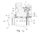
- a first stop 36 and a second stop 35 are arranged in the form of thrust washers for thrust bearings, which are each arranged next to a locking ring 33 which is inserted in an annular groove on the transmission shaft 34.
- a first thrust bearing 30 is arranged between the first stop 36 and the idler gear 20.
- a second thrust bearing 31 is disposed between the second stopper 35 and the idler gear 20.
- Both thrust bearings 30, 31 each have a cage 32, which holds a plurality of rolling elements 25, preferably needles, and at least one tunnel roller 10 rolling.
- the at least one tunnel roller 10 also here has a larger outer diameter 12 (see Fig. 2 ) as the rolling elements 25 on.
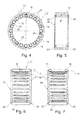
- the configuration of the cage 32 or the arrangement of the at least one tunnel roller 10 of the first and second thrust bearings 30, 31 is comparable to the design of the radial bearing 24 4 and 5 , so that here is dispensed with a further description of this. It is merely to be noted that the cage 32 is disc-shaped and axially perforated by pockets. The rolling elements 25 and tunnel rollers 10 are only with their axes of rotation aligned so that they intersect under load in a radial plane, the axis of rotation 11 of the gear shaft 34 together in one point.
Landscapes
- Engineering & Computer Science (AREA)
- General Engineering & Computer Science (AREA)
- Mechanical Engineering (AREA)
- Rolling Contact Bearings (AREA)
Applications Claiming Priority (2)
| Application Number | Priority Date | Filing Date | Title |
|---|---|---|---|
| DE102011080027 | 2011-07-28 | ||
| DE102011080021 | 2011-07-28 |
Publications (2)
| Publication Number | Publication Date |
|---|---|
| EP2551537A1 true EP2551537A1 (fr) | 2013-01-30 |
| EP2551537B1 EP2551537B1 (fr) | 2015-04-15 |
Family
ID=46052570
Family Applications (2)
| Application Number | Title | Priority Date | Filing Date |
|---|---|---|---|
| EP20120165920 Withdrawn EP2551538A1 (fr) | 2011-07-28 | 2012-04-27 | Palier radial pour roue libre d'une boîte de vitesse de véhicule automobile |
| EP20120165917 Not-in-force EP2551537B1 (fr) | 2011-07-28 | 2012-04-27 | Palier de roue libre pour boîte de vitesses de véhicule automobile |
Family Applications Before (1)
| Application Number | Title | Priority Date | Filing Date |
|---|---|---|---|
| EP20120165920 Withdrawn EP2551538A1 (fr) | 2011-07-28 | 2012-04-27 | Palier radial pour roue libre d'une boîte de vitesse de véhicule automobile |
Country Status (1)
| Country | Link |
|---|---|
| EP (2) | EP2551538A1 (fr) |
Cited By (2)
| Publication number | Priority date | Publication date | Assignee | Title |
|---|---|---|---|---|
| DE102013217517A1 (de) * | 2013-09-03 | 2015-03-05 | Schaeffler Technologies Gmbh & Co. Kg | Wälzlager und Wälzkörper zum Abbau elektrischer Potentiale |
| DE102015215707A1 (de) | 2015-08-18 | 2017-02-23 | Schaeffler Technologies AG & Co. KG | Getriebelager mit als Hohlrollen ausgebildeten Wälzkörpern |
Families Citing this family (3)
| Publication number | Priority date | Publication date | Assignee | Title |
|---|---|---|---|---|
| DE102016210651B4 (de) | 2016-06-15 | 2022-03-03 | Schaeffler Technologies AG & Co. KG | Getriebeanordnung mit Gleitlagereinrichtung |
| DE102016210654A1 (de) | 2016-06-15 | 2017-04-06 | Schaeffler Technologies AG & Co. KG | Getriebeanordnung für ein Fahrzeug |
| DE102016210656A1 (de) | 2016-06-15 | 2017-05-11 | Schaeffler Technologies AG & Co. KG | Getriebeanordnung für ein Fahrzeug |
Citations (8)
| Publication number | Priority date | Publication date | Assignee | Title |
|---|---|---|---|---|
| DE826384C (de) * | 1949-04-12 | 1952-01-03 | Wilhelm Hedtmann Fa | Elastisches Lager, insbesondere Nadellager |
| DE1575611B1 (de) | 1966-06-02 | 1971-04-22 | Skf Kugellagerfabriken Gmbh | Lagerung eines auf einer getriebewelle eines kraftfahrzeug schaltgetriebes frei drehbaren zahnrades |
| DE7139580U (de) * | 1972-11-09 | Rollway Bearing Co Inc | Rolle für ein Wälzlager | |
| JPH02163509A (ja) | 1988-12-15 | 1990-06-22 | Nippon Seiko Kk | 回転支持部 |
| DE19734980A1 (de) | 1997-08-13 | 1999-02-18 | Schaeffler Waelzlager Ohg | Zahnräderwechselgetriebe |
| DE10037401A1 (de) * | 2000-08-01 | 2002-02-14 | Daimler Chrysler Ag | Schalteinrichtung |
| EP1921334A2 (fr) | 2006-11-09 | 2008-05-14 | Delphi Technologies, Inc. | Roulement à aiguilles |
| DE102007057045A1 (de) * | 2007-11-27 | 2009-05-28 | Schaeffler Kg | Spielfreies Radiallager |
Family Cites Families (1)
| Publication number | Priority date | Publication date | Assignee | Title |
|---|---|---|---|---|
| CH232973A (de) * | 1942-03-25 | 1944-06-30 | Rheinmetall Borsig Ag | In einem Rohr gleichachsig zu demselben gelagerte Welle. |
-
2012
- 2012-04-27 EP EP20120165920 patent/EP2551538A1/fr not_active Withdrawn
- 2012-04-27 EP EP20120165917 patent/EP2551537B1/fr not_active Not-in-force
Patent Citations (8)
| Publication number | Priority date | Publication date | Assignee | Title |
|---|---|---|---|---|
| DE7139580U (de) * | 1972-11-09 | Rollway Bearing Co Inc | Rolle für ein Wälzlager | |
| DE826384C (de) * | 1949-04-12 | 1952-01-03 | Wilhelm Hedtmann Fa | Elastisches Lager, insbesondere Nadellager |
| DE1575611B1 (de) | 1966-06-02 | 1971-04-22 | Skf Kugellagerfabriken Gmbh | Lagerung eines auf einer getriebewelle eines kraftfahrzeug schaltgetriebes frei drehbaren zahnrades |
| JPH02163509A (ja) | 1988-12-15 | 1990-06-22 | Nippon Seiko Kk | 回転支持部 |
| DE19734980A1 (de) | 1997-08-13 | 1999-02-18 | Schaeffler Waelzlager Ohg | Zahnräderwechselgetriebe |
| DE10037401A1 (de) * | 2000-08-01 | 2002-02-14 | Daimler Chrysler Ag | Schalteinrichtung |
| EP1921334A2 (fr) | 2006-11-09 | 2008-05-14 | Delphi Technologies, Inc. | Roulement à aiguilles |
| DE102007057045A1 (de) * | 2007-11-27 | 2009-05-28 | Schaeffler Kg | Spielfreies Radiallager |
Cited By (2)
| Publication number | Priority date | Publication date | Assignee | Title |
|---|---|---|---|---|
| DE102013217517A1 (de) * | 2013-09-03 | 2015-03-05 | Schaeffler Technologies Gmbh & Co. Kg | Wälzlager und Wälzkörper zum Abbau elektrischer Potentiale |
| DE102015215707A1 (de) | 2015-08-18 | 2017-02-23 | Schaeffler Technologies AG & Co. KG | Getriebelager mit als Hohlrollen ausgebildeten Wälzkörpern |
Also Published As
| Publication number | Publication date |
|---|---|
| EP2551538A1 (fr) | 2013-01-30 |
| EP2551537B1 (fr) | 2015-04-15 |
Similar Documents
| Publication | Publication Date | Title |
|---|---|---|
| EP1896740B1 (fr) | Palier a roulement oblique multi-rangees comportant des rondelles en tandem, notamment destine a loger l'arbre a pignon conique d'une transmission a essieu arriere moteur d'un vehicule | |
| DE102007019482A1 (de) | Mehrreihiges Großwälzlager, insbesondere Axial-Radiallager zur Hauptlagerung der Rotorwelle einer Windkraftanlage | |
| DE102011004706A1 (de) | Kegelrollenlager mit Käfig | |
| DE102007004998A1 (de) | Drehlageranordnung | |
| EP2551537B1 (fr) | Palier de roue libre pour boîte de vitesses de véhicule automobile | |
| EP2596257A1 (fr) | Système de palier à roulement muni d'un dispositif de retenue | |
| EP2753842A1 (fr) | Dispositif à roue libre | |
| DE112004002814B4 (de) | Zusammengesetztes Wälzlager | |
| DE2918601A1 (de) | Waelzlagerkaefig fuer ein pilotlager in einem kraftfahrzeug-wechselgetriebe | |
| EP1957811A1 (fr) | Roulement radial, en particulier roulement rainure a une rangee | |
| EP2935920A1 (fr) | Dispositif de palier axial | |
| WO1993017252A1 (fr) | Roulement de roue folle silencieux | |
| DE102012207073A1 (de) | Differenzial | |
| DE102005027186B4 (de) | Wälzlagerkäfig und Losradlager | |
| DE102006044802A1 (de) | Kombiniertes Rollen-Kugellager | |
| DE102012207067A1 (de) | Rollenlager und Getriebe mit einem Rollenlager | |
| DE102009013038B4 (de) | Tripodegelenkrolle und Tripodegelenk | |
| DE102010011462A1 (de) | Kegelrollenlager mit profilierter Laufbahn | |
| DE102008045848A1 (de) | Planetengetriebe | |
| WO2008068123A1 (fr) | Palier de soutien d'une transmission à embrayage double | |
| DE102012207071A1 (de) | Lagerstelle zur drehbaren Lagerung eines Pumpenrades eines Drehmomentwandlers, Rollenlager der Lagerstelle und Getriebe mit einem Drehmomentwandler und der Lagerstelle | |
| WO2011020657A1 (fr) | Cage de corps de roulement | |
| DE102015223125B4 (de) | Lagerstelle mit zwei Polygonlagern und zweistufiger Steifigkeitskennlinie | |
| DE102016222451A1 (de) | Rollenlager und Getriebevorrichtung mit einem Rollenlager | |
| DE102013226072B4 (de) | Radialrollenwälzeinrichtung sowie Getriebe mit der Radialrollenwälzeinrichtung |
Legal Events
| Date | Code | Title | Description |
|---|---|---|---|
| PUAI | Public reference made under article 153(3) epc to a published international application that has entered the european phase |
Free format text: ORIGINAL CODE: 0009012 |
|
| 17P | Request for examination filed |
Effective date: 20120427 |
|
| AK | Designated contracting states |
Kind code of ref document: A1 Designated state(s): AL AT BE BG CH CY CZ DE DK EE ES FI FR GB GR HR HU IE IS IT LI LT LU LV MC MK MT NL NO PL PT RO RS SE SI SK SM TR |
|
| AX | Request for extension of the european patent |
Extension state: BA ME |
|
| 17Q | First examination report despatched |
Effective date: 20130118 |
|
| RBV | Designated contracting states (corrected) |
Designated state(s): AL AT BE BG CH CY CZ DE DK EE ES FI FR GB GR HR HU IE IS IT LI LT LU LV MC MK MT NL NO PL PT RO RS SE SI SK SM TR |
|
| RAP1 | Party data changed (applicant data changed or rights of an application transferred) |
Owner name: SCHAEFFLER TECHNOLOGIES GMBH & CO. KG |
|
| GRAP | Despatch of communication of intention to grant a patent |
Free format text: ORIGINAL CODE: EPIDOSNIGR1 |
|
| INTG | Intention to grant announced |
Effective date: 20141216 |
|
| RAP1 | Party data changed (applicant data changed or rights of an application transferred) |
Owner name: SCHAEFFLER TECHNOLOGIES AG & CO. KG |
|
| GRAS | Grant fee paid |
Free format text: ORIGINAL CODE: EPIDOSNIGR3 |
|
| GRAA | (expected) grant |
Free format text: ORIGINAL CODE: 0009210 |
|
| AK | Designated contracting states |
Kind code of ref document: B1 Designated state(s): AL AT BE BG CH CY CZ DE DK EE ES FI FR GB GR HR HU IE IS IT LI LT LU LV MC MK MT NL NO PL PT RO RS SE SI SK SM TR |
|
| REG | Reference to a national code |
Ref country code: GB Ref legal event code: FG4D Free format text: NOT ENGLISH Ref country code: CH Ref legal event code: EP |
|
| REG | Reference to a national code |
Ref country code: IE Ref legal event code: FG4D Free format text: LANGUAGE OF EP DOCUMENT: GERMAN |
|
| REG | Reference to a national code |
Ref country code: AT Ref legal event code: REF Ref document number: 722173 Country of ref document: AT Kind code of ref document: T Effective date: 20150515 |
|
| REG | Reference to a national code |
Ref country code: DE Ref legal event code: R096 Ref document number: 502012002842 Country of ref document: DE Effective date: 20150528 |
|
| REG | Reference to a national code |
Ref country code: NL Ref legal event code: VDEP Effective date: 20150415 |
|
| REG | Reference to a national code |
Ref country code: LT Ref legal event code: MG4D |
|
| PG25 | Lapsed in a contracting state [announced via postgrant information from national office to epo] |
Ref country code: NL Free format text: LAPSE BECAUSE OF FAILURE TO SUBMIT A TRANSLATION OF THE DESCRIPTION OR TO PAY THE FEE WITHIN THE PRESCRIBED TIME-LIMIT Effective date: 20150415 |
|
| PG25 | Lapsed in a contracting state [announced via postgrant information from national office to epo] |
Ref country code: NO Free format text: LAPSE BECAUSE OF FAILURE TO SUBMIT A TRANSLATION OF THE DESCRIPTION OR TO PAY THE FEE WITHIN THE PRESCRIBED TIME-LIMIT Effective date: 20150715 Ref country code: ES Free format text: LAPSE BECAUSE OF FAILURE TO SUBMIT A TRANSLATION OF THE DESCRIPTION OR TO PAY THE FEE WITHIN THE PRESCRIBED TIME-LIMIT Effective date: 20150415 Ref country code: FI Free format text: LAPSE BECAUSE OF FAILURE TO SUBMIT A TRANSLATION OF THE DESCRIPTION OR TO PAY THE FEE WITHIN THE PRESCRIBED TIME-LIMIT Effective date: 20150415 Ref country code: LT Free format text: LAPSE BECAUSE OF FAILURE TO SUBMIT A TRANSLATION OF THE DESCRIPTION OR TO PAY THE FEE WITHIN THE PRESCRIBED TIME-LIMIT Effective date: 20150415 Ref country code: HR Free format text: LAPSE BECAUSE OF FAILURE TO SUBMIT A TRANSLATION OF THE DESCRIPTION OR TO PAY THE FEE WITHIN THE PRESCRIBED TIME-LIMIT Effective date: 20150415 Ref country code: PT Free format text: LAPSE BECAUSE OF FAILURE TO SUBMIT A TRANSLATION OF THE DESCRIPTION OR TO PAY THE FEE WITHIN THE PRESCRIBED TIME-LIMIT Effective date: 20150817 |
|
| PG25 | Lapsed in a contracting state [announced via postgrant information from national office to epo] |
Ref country code: IS Free format text: LAPSE BECAUSE OF FAILURE TO SUBMIT A TRANSLATION OF THE DESCRIPTION OR TO PAY THE FEE WITHIN THE PRESCRIBED TIME-LIMIT Effective date: 20150815 Ref country code: RS Free format text: LAPSE BECAUSE OF FAILURE TO SUBMIT A TRANSLATION OF THE DESCRIPTION OR TO PAY THE FEE WITHIN THE PRESCRIBED TIME-LIMIT Effective date: 20150415 Ref country code: LV Free format text: LAPSE BECAUSE OF FAILURE TO SUBMIT A TRANSLATION OF THE DESCRIPTION OR TO PAY THE FEE WITHIN THE PRESCRIBED TIME-LIMIT Effective date: 20150415 Ref country code: GR Free format text: LAPSE BECAUSE OF FAILURE TO SUBMIT A TRANSLATION OF THE DESCRIPTION OR TO PAY THE FEE WITHIN THE PRESCRIBED TIME-LIMIT Effective date: 20150716 |
|
| REG | Reference to a national code |
Ref country code: CH Ref legal event code: PL |
|
| REG | Reference to a national code |
Ref country code: DE Ref legal event code: R097 Ref document number: 502012002842 Country of ref document: DE |
|
| REG | Reference to a national code |
Ref country code: IE Ref legal event code: MM4A |
|
| PG25 | Lapsed in a contracting state [announced via postgrant information from national office to epo] |
Ref country code: LI Free format text: LAPSE BECAUSE OF NON-PAYMENT OF DUE FEES Effective date: 20150430 Ref country code: MC Free format text: LAPSE BECAUSE OF FAILURE TO SUBMIT A TRANSLATION OF THE DESCRIPTION OR TO PAY THE FEE WITHIN THE PRESCRIBED TIME-LIMIT Effective date: 20150415 Ref country code: EE Free format text: LAPSE BECAUSE OF FAILURE TO SUBMIT A TRANSLATION OF THE DESCRIPTION OR TO PAY THE FEE WITHIN THE PRESCRIBED TIME-LIMIT Effective date: 20150415 Ref country code: DK Free format text: LAPSE BECAUSE OF FAILURE TO SUBMIT A TRANSLATION OF THE DESCRIPTION OR TO PAY THE FEE WITHIN THE PRESCRIBED TIME-LIMIT Effective date: 20150415 Ref country code: IT Free format text: LAPSE BECAUSE OF FAILURE TO SUBMIT A TRANSLATION OF THE DESCRIPTION OR TO PAY THE FEE WITHIN THE PRESCRIBED TIME-LIMIT Effective date: 20150415 Ref country code: CH Free format text: LAPSE BECAUSE OF NON-PAYMENT OF DUE FEES Effective date: 20150430 |
|
| PLBE | No opposition filed within time limit |
Free format text: ORIGINAL CODE: 0009261 |
|
| STAA | Information on the status of an ep patent application or granted ep patent |
Free format text: STATUS: NO OPPOSITION FILED WITHIN TIME LIMIT |
|
| PG25 | Lapsed in a contracting state [announced via postgrant information from national office to epo] |
Ref country code: SK Free format text: LAPSE BECAUSE OF FAILURE TO SUBMIT A TRANSLATION OF THE DESCRIPTION OR TO PAY THE FEE WITHIN THE PRESCRIBED TIME-LIMIT Effective date: 20150415 Ref country code: CZ Free format text: LAPSE BECAUSE OF FAILURE TO SUBMIT A TRANSLATION OF THE DESCRIPTION OR TO PAY THE FEE WITHIN THE PRESCRIBED TIME-LIMIT Effective date: 20150415 Ref country code: RO Free format text: LAPSE BECAUSE OF NON-PAYMENT OF DUE FEES Effective date: 20150415 Ref country code: PL Free format text: LAPSE BECAUSE OF FAILURE TO SUBMIT A TRANSLATION OF THE DESCRIPTION OR TO PAY THE FEE WITHIN THE PRESCRIBED TIME-LIMIT Effective date: 20150415 |
|
| REG | Reference to a national code |
Ref country code: FR Ref legal event code: ST Effective date: 20160205 |
|
| 26N | No opposition filed |
Effective date: 20160118 |
|
| PG25 | Lapsed in a contracting state [announced via postgrant information from national office to epo] |
Ref country code: IE Free format text: LAPSE BECAUSE OF NON-PAYMENT OF DUE FEES Effective date: 20150427 |
|
| PG25 | Lapsed in a contracting state [announced via postgrant information from national office to epo] |
Ref country code: SI Free format text: LAPSE BECAUSE OF FAILURE TO SUBMIT A TRANSLATION OF THE DESCRIPTION OR TO PAY THE FEE WITHIN THE PRESCRIBED TIME-LIMIT Effective date: 20150415 Ref country code: FR Free format text: LAPSE BECAUSE OF NON-PAYMENT OF DUE FEES Effective date: 20150615 |
|
| GBPC | Gb: european patent ceased through non-payment of renewal fee |
Effective date: 20160427 |
|
| PG25 | Lapsed in a contracting state [announced via postgrant information from national office to epo] |
Ref country code: MT Free format text: LAPSE BECAUSE OF FAILURE TO SUBMIT A TRANSLATION OF THE DESCRIPTION OR TO PAY THE FEE WITHIN THE PRESCRIBED TIME-LIMIT Effective date: 20150415 |
|
| PG25 | Lapsed in a contracting state [announced via postgrant information from national office to epo] |
Ref country code: GB Free format text: LAPSE BECAUSE OF NON-PAYMENT OF DUE FEES Effective date: 20160427 |
|
| PG25 | Lapsed in a contracting state [announced via postgrant information from national office to epo] |
Ref country code: HU Free format text: LAPSE BECAUSE OF FAILURE TO SUBMIT A TRANSLATION OF THE DESCRIPTION OR TO PAY THE FEE WITHIN THE PRESCRIBED TIME-LIMIT; INVALID AB INITIO Effective date: 20120427 Ref country code: SM Free format text: LAPSE BECAUSE OF FAILURE TO SUBMIT A TRANSLATION OF THE DESCRIPTION OR TO PAY THE FEE WITHIN THE PRESCRIBED TIME-LIMIT Effective date: 20150415 Ref country code: BG Free format text: LAPSE BECAUSE OF FAILURE TO SUBMIT A TRANSLATION OF THE DESCRIPTION OR TO PAY THE FEE WITHIN THE PRESCRIBED TIME-LIMIT Effective date: 20150415 |
|
| PG25 | Lapsed in a contracting state [announced via postgrant information from national office to epo] |
Ref country code: CY Free format text: LAPSE BECAUSE OF FAILURE TO SUBMIT A TRANSLATION OF THE DESCRIPTION OR TO PAY THE FEE WITHIN THE PRESCRIBED TIME-LIMIT Effective date: 20150415 Ref country code: SE Free format text: LAPSE BECAUSE OF FAILURE TO SUBMIT A TRANSLATION OF THE DESCRIPTION OR TO PAY THE FEE WITHIN THE PRESCRIBED TIME-LIMIT Effective date: 20150415 |
|
| PG25 | Lapsed in a contracting state [announced via postgrant information from national office to epo] |
Ref country code: BE Free format text: LAPSE BECAUSE OF NON-PAYMENT OF DUE FEES Effective date: 20150430 |
|
| PG25 | Lapsed in a contracting state [announced via postgrant information from national office to epo] |
Ref country code: TR Free format text: LAPSE BECAUSE OF FAILURE TO SUBMIT A TRANSLATION OF THE DESCRIPTION OR TO PAY THE FEE WITHIN THE PRESCRIBED TIME-LIMIT Effective date: 20150415 |
|
| PG25 | Lapsed in a contracting state [announced via postgrant information from national office to epo] |
Ref country code: LU Free format text: LAPSE BECAUSE OF NON-PAYMENT OF DUE FEES Effective date: 20150427 |
|
| REG | Reference to a national code |
Ref country code: AT Ref legal event code: MM01 Ref document number: 722173 Country of ref document: AT Kind code of ref document: T Effective date: 20170427 |
|
| PG25 | Lapsed in a contracting state [announced via postgrant information from national office to epo] |
Ref country code: MK Free format text: LAPSE BECAUSE OF FAILURE TO SUBMIT A TRANSLATION OF THE DESCRIPTION OR TO PAY THE FEE WITHIN THE PRESCRIBED TIME-LIMIT Effective date: 20150415 |
|
| PG25 | Lapsed in a contracting state [announced via postgrant information from national office to epo] |
Ref country code: AT Free format text: LAPSE BECAUSE OF NON-PAYMENT OF DUE FEES Effective date: 20170427 |
|
| PG25 | Lapsed in a contracting state [announced via postgrant information from national office to epo] |
Ref country code: AL Free format text: LAPSE BECAUSE OF FAILURE TO SUBMIT A TRANSLATION OF THE DESCRIPTION OR TO PAY THE FEE WITHIN THE PRESCRIBED TIME-LIMIT Effective date: 20150415 |
|
| PGFP | Annual fee paid to national office [announced via postgrant information from national office to epo] |
Ref country code: DE Payment date: 20190621 Year of fee payment: 8 |
|
| REG | Reference to a national code |
Ref country code: DE Ref legal event code: R119 Ref document number: 502012002842 Country of ref document: DE |
|
| PG25 | Lapsed in a contracting state [announced via postgrant information from national office to epo] |
Ref country code: DE Free format text: LAPSE BECAUSE OF NON-PAYMENT OF DUE FEES Effective date: 20201103 |
|
| P01 | Opt-out of the competence of the unified patent court (upc) registered |
Effective date: 20230523 |