EP2551581B1 - Fahrzeugscheinwerfer - Google Patents
Fahrzeugscheinwerfer Download PDFInfo
- Publication number
- EP2551581B1 EP2551581B1 EP12177836.9A EP12177836A EP2551581B1 EP 2551581 B1 EP2551581 B1 EP 2551581B1 EP 12177836 A EP12177836 A EP 12177836A EP 2551581 B1 EP2551581 B1 EP 2551581B1
- Authority
- EP
- European Patent Office
- Prior art keywords
- reflection surface
- light
- light source
- shade
- distribution pattern
- Prior art date
- Legal status (The legal status is an assumption and is not a legal conclusion. Google has not performed a legal analysis and makes no representation as to the accuracy of the status listed.)
- Not-in-force
Links
Images




Classifications
-
- F—MECHANICAL ENGINEERING; LIGHTING; HEATING; WEAPONS; BLASTING
- F21—LIGHTING
- F21S—NON-PORTABLE LIGHTING DEVICES; SYSTEMS THEREOF; VEHICLE LIGHTING DEVICES SPECIALLY ADAPTED FOR VEHICLE EXTERIORS
- F21S41/00—Illuminating devices specially adapted for vehicle exteriors, e.g. headlamps
- F21S41/30—Illuminating devices specially adapted for vehicle exteriors, e.g. headlamps characterised by reflectors
- F21S41/32—Optical layout thereof
- F21S41/33—Multi-surface reflectors, e.g. reflectors with facets or reflectors with portions of different curvature
- F21S41/331—Multi-surface reflectors, e.g. reflectors with facets or reflectors with portions of different curvature the reflector consisting of complete annular areas
- F21S41/333—Multi-surface reflectors, e.g. reflectors with facets or reflectors with portions of different curvature the reflector consisting of complete annular areas with discontinuity at the junction between adjacent areas
-
- F—MECHANICAL ENGINEERING; LIGHTING; HEATING; WEAPONS; BLASTING
- F21—LIGHTING
- F21S—NON-PORTABLE LIGHTING DEVICES; SYSTEMS THEREOF; VEHICLE LIGHTING DEVICES SPECIALLY ADAPTED FOR VEHICLE EXTERIORS
- F21S41/00—Illuminating devices specially adapted for vehicle exteriors, e.g. headlamps
- F21S41/10—Illuminating devices specially adapted for vehicle exteriors, e.g. headlamps characterised by the light source
- F21S41/14—Illuminating devices specially adapted for vehicle exteriors, e.g. headlamps characterised by the light source characterised by the type of light source
- F21S41/141—Light emitting diodes [LED]
- F21S41/147—Light emitting diodes [LED] the main emission direction of the LED being angled to the optical axis of the illuminating device
- F21S41/148—Light emitting diodes [LED] the main emission direction of the LED being angled to the optical axis of the illuminating device the main emission direction of the LED being perpendicular to the optical axis
-
- F—MECHANICAL ENGINEERING; LIGHTING; HEATING; WEAPONS; BLASTING
- F21—LIGHTING
- F21S—NON-PORTABLE LIGHTING DEVICES; SYSTEMS THEREOF; VEHICLE LIGHTING DEVICES SPECIALLY ADAPTED FOR VEHICLE EXTERIORS
- F21S41/00—Illuminating devices specially adapted for vehicle exteriors, e.g. headlamps
- F21S41/30—Illuminating devices specially adapted for vehicle exteriors, e.g. headlamps characterised by reflectors
- F21S41/32—Optical layout thereof
- F21S41/33—Multi-surface reflectors, e.g. reflectors with facets or reflectors with portions of different curvature
- F21S41/334—Multi-surface reflectors, e.g. reflectors with facets or reflectors with portions of different curvature the reflector consisting of patch like sectors
- F21S41/335—Multi-surface reflectors, e.g. reflectors with facets or reflectors with portions of different curvature the reflector consisting of patch like sectors with continuity at the junction between adjacent areas
-
- F—MECHANICAL ENGINEERING; LIGHTING; HEATING; WEAPONS; BLASTING
- F21—LIGHTING
- F21S—NON-PORTABLE LIGHTING DEVICES; SYSTEMS THEREOF; VEHICLE LIGHTING DEVICES SPECIALLY ADAPTED FOR VEHICLE EXTERIORS
- F21S41/00—Illuminating devices specially adapted for vehicle exteriors, e.g. headlamps
- F21S41/40—Illuminating devices specially adapted for vehicle exteriors, e.g. headlamps characterised by screens, non-reflecting members, light-shielding members or fixed shades
-
- F—MECHANICAL ENGINEERING; LIGHTING; HEATING; WEAPONS; BLASTING
- F21—LIGHTING
- F21S—NON-PORTABLE LIGHTING DEVICES; SYSTEMS THEREOF; VEHICLE LIGHTING DEVICES SPECIALLY ADAPTED FOR VEHICLE EXTERIORS
- F21S41/00—Illuminating devices specially adapted for vehicle exteriors, e.g. headlamps
- F21S41/60—Illuminating devices specially adapted for vehicle exteriors, e.g. headlamps characterised by a variable light distribution
- F21S41/68—Illuminating devices specially adapted for vehicle exteriors, e.g. headlamps characterised by a variable light distribution by acting on screens
- F21S41/683—Illuminating devices specially adapted for vehicle exteriors, e.g. headlamps characterised by a variable light distribution by acting on screens by moving screens
- F21S41/692—Shields, i.e. screens not creating an image meant to be projected
-
- F—MECHANICAL ENGINEERING; LIGHTING; HEATING; WEAPONS; BLASTING
- F21—LIGHTING
- F21W—INDEXING SCHEME ASSOCIATED WITH SUBCLASSES F21K, F21L, F21S and F21V, RELATING TO USES OR APPLICATIONS OF LIGHTING DEVICES OR SYSTEMS
- F21W2102/00—Exterior vehicle lighting devices for illuminating purposes
- F21W2102/10—Arrangement or contour of the emitted light
- F21W2102/17—Arrangement or contour of the emitted light for regions other than high beam or low beam
- F21W2102/18—Arrangement or contour of the emitted light for regions other than high beam or low beam for overhead signs
Definitions
- the present invention relates to a vehicle headlamp employing a semiconductor-type light source as a light source to switch and emit a light distribution pattern for low beam (for passing) and a light distribution pattern for high beam (for cruising).
- a vehicle headlamp employing a semiconductor-type light source as a light source is conventionally known (for example, Japanese Unexamined Patent Application Publication No. 2010-18178 ).
- a conventional vehicle headlamp will be described.
- the conventional vehicle headlamp is provided for switching and emitting a light distribution pattern for DTL and a light distribution pattern for cruising by means of a switch of a scattering lens.
- JP2010-192412 discloses a vehicle headlamp according to the preamble of claim 1.
- a vehicle headlamp adapted to switch and emit a light distribution pattern for low beam and a light distribution pattern for high beam is also conventionally known (for example, Japanese Unexamined Patent Application Publication No. 2000-200510 ).
- a conventional vehicle headlamp will be described.
- the conventional vehicle headlamp is provided in such a manner that: a shade is positioned in a low beam location; light from a discharge lamp is reflected on a first reflection surface to thereby obtain a light distribution pattern for low beam; the shade is switched and positioned in a high beam location; and the light from the discharge lamp is reflected on the first reflection surface and a second reflection surface to thereby obtain a light distribution pattern for high beam.
- the former one of the conventional vehicle headlamps has entailed a problem that a light distribution pattern for passing and a light distribution pattern for cruising cannot be switched and emitted.
- the latter one of the conventional vehicle headlamps has entailed a problem that a discharge lamp is used as a light source, whereas a semiconductor-type light source is not used as a light source.
- the present invention has been made in order to solve the problems described above, and it is an object of the present invention to provide a vehicle headlamp employing a semiconductor-type light source as a light source to thereby switch and emit a light distribution pattern for low beam and a light distribution patter for high beam.
- a vehicle headlamp according to the present invention comprising:
- a vehicle headlamp according to the present invention is provided in such a manner that: if a shade is positioned in a first location, a fraction of light from a semiconductor-type light source is shaded by means of the shade; the remaining light from the semiconductor-type light source, which is not shaded by means of the shade, is incident to a first reflection surface; and the incident light is emitted after reflected as a light distribution pattern for high beam.
- the vehicle headlamp according to the present invention is capable of employing a semiconductor-type light source as a light source to thereby switch and emit a light distribution pattern for low beam and a light distribution pattern for high beam.
- this vehicle headlamp is capable of switching and emitting a light distribution pattern for low beam and a light distribution pattern for high beam by means of one lamp unit employing a semiconductor light source as a light source (by means of one semiconductor-type light source).
- a vehicle headlamp according to the preset invention is provided in such a manner that a third reflection surface is provided between a first reflection surface and a second reflection surface.
- the vehicle headlamp according to the present invention when the shade is positioned in the first location, light from the semiconductor-type light source, the light having leaked due to displacement of the shade, is incident to the second reflection surface as it is, it becomes possible to reliably prevent the incident light from being troublesome light at the time of emission of a light distribution pattern of low beam.
- the present invention is not limited by the embodiments.
- the front, back, upside, downside, left, and light respectively correspond to the front, back, upside, downside, left and right in a case in which the vehicle headlamp according to the present invention is equipped in a vehicle.
- a combination of uppercase letters with hyphen "VU-VD” designates a vertical line from top to bottom of a screen.
- a combination of uppercase letters with hyphen "HL-HR” designates a horizontal line from left to right of the screen.
- reference numeral 1 designates a vehicle headlamp (such as a headlamp, for example) in the exemplary embodiment.
- the vehicle headlamp 1 is mounted on each of the left and right end parts of a front portion of a vehicle.
- the vehicle headlamp 1 is provided with a lamp housing (not shown), a lamp lens (not shown), a semiconductor-type light source 2, a reflector 3, a shade 4, a driving mechanism 5, a heat sink member 6, and a mount bracket 7.
- the semiconductor-type light source 2, the reflector 3, the shade 4, the driving mechanism 5, the heat sink member 6, and the mount bracket 7 configure a lamp unit.
- the lamp housing and the lamp lens define a lamp room (not shown).
- the lamp unit is disposed in the lamp room, and is mounted on the lamp housing via an optical axis adjustment mechanism for vertical direction (not shown) and an optical axis adjustment mechanism for horizontal direction (not shown).
- the semiconductor-type light source 2 uses a light source of one's own light emitting semiconductor-type such as an LED or an EL (an organic EL) or the like, for example, in other words, a semiconductor-type light source (an LED in this exemplary embodiment).
- the semiconductor-type light source 2 has a light emitting portion in which one or a plurality of light emitting chips (not shown) is provided.
- the semiconductor-type light source 2 is made of: a board (not shown); the light emitting chips that are appropriately disposed and provided on the board; and a sealing resin member (not shown) adapted to seal the light emitting chips.
- the semiconductor light source 2 is mounted on the heat sink 6 by means of a mount member 8. A light emitting surface of the light emitting portion of the semiconductor light source 2 is oriented to the downside in a vertical direction.
- the reflector 3 is made of a light non-transmissible member, in this example, a resin member.
- the reflector 3 is mounted on at least one of the head sink member 6 and the mount bracket 7.
- the reflector 3 opens at a portion of the upside U and the front side F, and closes at other portions.
- a first reflection surface 9, a second reflection surface 10, and a third reflection surface 11 that are made of a parabola-based free curved surface are respectively provided on an interior face of the closed portion of the reflector 3.
- the first reflection surface 9, the second reflection surface 10, and the third reflection surface 11 are respectively provided at an opposite side to the light emitting surface, in other words, in a space of the downside of the semiconductor-type light source 2.
- the first reflection surface 9 is provided in proximity to the semiconductor-type light source 2.
- the first reflection surface 9 is a reflection surface adapted to reflect and emit incident light of rays of the light from the semiconductor-type light source 2 as a light distribution pattern for low beam LP (refer to FIG. 6 and FIG. 7 ).
- the second reflection surface 10 is provided outside of the first reflection surface 9 in such a manner as to be spaced from the semiconductor-type light source 2.
- the second reflection surface 10 is a reflection surface adapted to reflect and emit the incident light from among beams of the light from the semiconductor-type light source 2 as the light distribution pattern for high beam HP (refer to FIG. 8 ).
- the third reflection surface 11 is provided between the first reflection surface 9 and the second reflection surface 10.
- the third reflection surface 11 is a reflection surface adapted to reflect and emit the incident light from among beams of the light from the semiconductor-type light source 2 as an auxiliary light distribution pattern, in this example, as a light distribution pattern for overhead sign OSP (refer to FIG. 6 ) or a light distribution pattern for front side BP (refer to FIG. 7 ).
- the light distribution pattern for overhead sign OSP is adapted to illuminate an overhead sign (not shown) on the upside more than a cutoff line CL of the light distribution pattern for low beam LP, in other words, overhead of the vehicle.
- the light distribution pattern for front side BP is adapted to illuminate a portion of the downside of the light distribution pattern for low beam LP, in other words, the front side of a road surface.
- the light distribution pattern for overhead sign OSP and the light distribution pattern for front side BP are not those which disturb light distribution characteristics of the light distribution pattern for low beam LP.
- the second reflection surface 10 in this example, is made of eight segments at the left and right.
- the first reflection surface 9 and the third reflection surface 11, in this example, are made of one segment.
- Step heights 12 and 13 are respectively provided between the first reflection surface 9 and the third reflection surface 11 and between the third reflection surface 11 and the second reflection surface 10.
- the shade 4 is made of: a slide guide portion 14 that is formed in a recessed shape with a shallow bottom thereof; a shade portion 15 that is formed in a 1/4 spherical shape that is integrally provided at one end part (a front side end part) of the slide guide portion 14; and a fixing portion 16 that is integrally provided at the other end part (a back side end part) of the slide guide portion 14.
- An opening portion 17 is provided at an intermediate part of the slide guide portion 14.
- a fixing guide portion 18 is provided on one surface (an upper surface) of the reflector 3 and on the mount bracket 7.
- the slide guide portion 14 of the shade 4 is mounted movably (slidably) in one direction (in a forward/backward direction).
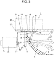
- the shade 4 is disposed movably between a first location (a back side location shown in FIG. 3 ) and a second location (a front side position shown in FIG. 4 ).
- the first location is a location in which the third reflection surface 11 is disposed on a straight line that connects the semiconductor-type light source 2 and an edge (an opening edge) of the shade portion 15 of the shade 4 to each other.
- the shade 4 When the shade 4 is positioned in the first location, as shown in FIG. 3 , a fraction of the light from the semiconductor-type light source 2 is shaded by means of the shade portion 15 of the shade 4 and then the remaining light is caused to be incident to the first reflection surface 9 and the third reflection surface 11.
- the shade 4 when the shade 4 is positioned in the second location, as shown in FIG. 4 , the light from the semiconductor-type light source 2 is caused to be incident to the first reflection surface 9 and the third reflection surface 11 and then is further caused to be incident to the second reflection surface 10.
- the driving mechanism 5 is a solenoid in this example.
- the driving mechanism 5 is adapted to move and switch the shade 4 between the first location and the second location.
- the driving mechanism 5 is made of: a solenoid main body potion 19; and a plunger (an advancing and retracting rod) 20 that is provided retractably from the solenoid main body portion 19.
- the solenoid main body portion 19 of the driving mechanism 5 is mounted on at least one of the heat sink member 6 and the mount bracket 7.
- the plunger 20 of the driving mechanism 5 is mounted on the fixing portion 16 of the shade 4 via an L-shaped connecting member 21.
- this driving mechanism 5 causes the shade 4 to be positioned in the first location by means of a spring, although not shown (a spring that is incorporated in the driving mechanism 5 or a spring that is provided separately).
- a spring that is incorporated in the driving mechanism 5 or a spring that is provided separately.
- the plunger 20 advances against a spring force of the spring and then causes the shade 4 to move and switch from the first location to the second location.
- the plunger 20 is retracted by means of the spring force of the spring and then the shade 4 is caused to move and switch from the second location to the first location.
- the heat sink member 6 is made of: a horizontal plate portion 22; and a fin portion 23 that is integrally provided on one surface (an upper surface) of the horizontal plate portion 22. On the other surface (a lower surface) of the horizontal plate portion 22 of the heat sink member 6, the semiconductor-type light source 2 is mounted via the mount member 8.
- the mount bracket 7 is formed in the shape of a plate.
- a window portion 24 is provided at a center part of the mount bracket 7.
- the fixing guide portion 18 is provided at a center of one edge (an upper edge) of the window portion 24 of the mount bracket 7.
- One edge (the upper edge) of the mount bracket 7 is mounted on the other surface (the lower surface) of the horizontal plate portion 22 of the heat sink member 7. It is to be noted that the heat sink member 6 and the mount bracket 7 may be integrally structured.
- reference numeral 25 designates a centerline of a road surface
- reference numeral 26 designates a cruising lane of a driver's vehicle on a road surface
- reference numeral 27 designates an opposite lane.
- the vehicle headlamp 1 in the embodiment is made of the constituent elements as described above, and hereinafter, its related functions will be described.
- a solenoid main body portion 19 is established in a state in which no power is supplied.
- a shade 4 is positioned in a first location.
- a semiconductor-type light source 2 is lit.
- a shade portion 15 of the shaped 4 is shaded by means of a shade portion 15 of the shaped 4 that is positioned in the first location. The remaining light that is not shaded is reflected on a first reflection surface 9 and a third reflection surface 11.
- the reflected light L1 is emitted forward of a vehicle as a light distribution pattern for low beam LP having a cutoff line CL (refer to FIG. 6 and FIG. 7 ).
- the reflected light L2 is illuminated forward of the vehicle as a light distribution pattern for overhead sign OSP of an auxiliary light distribution pattern (refer to FIG. 6 ).
- the reflected light L2 is emitted forward of the vehicle as a light distribution pattern for front side BP (refer to FIG. 7 ).
- a road surface in the forward direction (front side) of the vehicle in other words, a cruising lane 26 and an opposite lane 27 are illuminated as a light distribution pattern for low beam LP.
- an overhead sign (not shown) on the forward overhead of the vehicle is illuminated as a light distribution pattern for overhead OSP of an auxiliary light distribution pattern (refer to FIG. 6 ), or alternatively, a road surface in the forward direction of the vehicle, in other words, a road surface on the front side is illuminated as a light distribution pattern for front side BP (refer to FIG. 7 ).
- another light distribution pattern for overhead sign may also be distributed as light between a cutoff line CL of a light distribution pattern for low beam LP and a light distribution pattern for overhead sign OSP of an auxiliary light distribution pattern.
- the reflected light L3 is emitted forward of the vehicle as a light distribution pattern for high beam HP.
- the light from the semiconductor-type light source 2 is incident to, and is reflected on, the first reflection surface 9 and the third reflection surface 11 as well.
- a light distribution pattern for low beam LP that is obtained by means of the reflected light L1 (refer to FIG. 4 ) is emitted to a lower halve of the light distribution pattern for high beam HP.
- a light distribution pattern for overhead sign OSP that is obtained by means of the reflected light L2 (refer to the arrow drawn by the solid line in FIG.
- the light distribution pattern for low beam LP, the light distribution patter for overhead sign OSP, or the light distribution pattern for front side BP are encompassed in the light distribution pattern for high beam HP; and therefore, these light distribution patterns are not shown in FIG. 8 . It is to be noted that part or all of the light distribution pattern for overhead sign OSP may be optically distributed at a slightly more upside (upper side) than that of the light distribution pattern for high beam HP.
- the vehicle headlamp 1 in the embodiment is made of the constituent elements and functions as described above, and hereinafter, its related advantageous effects will be described.
- the shade 4 if the shade 4 is positioned in the first location, a fraction of the light from the semiconductor-type light source 2 is shaded by means of the shade 4, the remaining light from the semiconductor-type light source 2, which is not shaded by means of the shade 4, is incident to the first reflection surface 9, and the incident light is reflected and emitted as a light distribution pattern for low beam LP.
- the shade 4 if the shade 4 is moved to, switched to, and positioned in the second location, the light from the semiconductor-type light source 2 is incident to the first reflection surface 9 and the second reflection surface 10 and then the incident light is reflected and emitted as a light distribution pattern for high beam HP.
- the vehicle headlamp 1 in the embodiment employs the semiconductor-type light source 2 as a light source, thereby making it possible to switch and emit the light distribution pattern for low beam LP and the light distribution pattern for high beam HP.
- this vehicle headlamp is capable of switching and emitting the light distribution pattern for low beam LP and the light distribution pattern for high beam by means of one lamp unit that employs the semiconductor-type light source 2 as a light source (by means of one semiconductor-type light source 2).
- the third reflection surface 11 is provided between the first reflection surface 9 and the second reflection surface 10.
- the shade 4 when the shade 4 is positioned in the first location, the light from the semiconductor-type light source 2, the light having leaked due to displacement of the shade 4, is incident to the second reflection surface 10 as it is, and it becomes possible to reliably prevent the incident light from being troublesome light at the time of emission of the light distribution pattern for low beam LP.
- a solenoid is used as a driving mechanism 5.
- the driving mechanism 5 there may be used a driving mechanism other than the solenoid, for example, a driving mechanism such as a motor.
Landscapes
- Engineering & Computer Science (AREA)
- General Engineering & Computer Science (AREA)
- Physics & Mathematics (AREA)
- Microelectronics & Electronic Packaging (AREA)
- Optics & Photonics (AREA)
- Non-Portable Lighting Devices Or Systems Thereof (AREA)
- Lighting Device Outwards From Vehicle And Optical Signal (AREA)
Claims (1)
- Fahrzeugscheinwerfer (1), umfassend:eine Lichtquelle (2);einen Reflektor (3) mit einer ersten Reflexionsfläche (9) und einer zweiten Reflexionsfläche (10);eine Blende (4), die so angeordnet ist, dass sie zwischen einem ersten Ort und einem zweiten Ort bewegbar ist, und die dazu eingerichtet ist, einen Teil des Lichts von der Lichtquelle (2) abzuschatten und zu bewirken, dass verbleibendes Licht auf die erste Reflexionsfläche fällt (9), wenn die Blende (4) an dem ersten Ort positioniert ist, und bewirkt, dass das Licht von der Lichtquelle (2) auf die erste Reflexionsfläche (9) und die zweite Reflexionsfläche (10) fällt, wenn die Blende (4) an dem zweiten Ort positioniert ist; undeinen Antriebsmechanismus (5), der dazu eingerichtet ist, die Blende (4) zwischen dem ersten Ort und dem zweiten Ort zu bewegen und umzuschalten, wobeidie erste Reflexionsfläche (9) eine Reflexionsfläche ist, die in der Nähe der Lichtquelle (2) vorgesehen ist, wobei die Reflexionsfläche dazu eingerichtet ist, einfallendes Licht aus den Strahlen des Lichts von der Lichtquelle (2) als Lichtverteilungsmuster für Abblendlicht (LP) zu reflektieren und zu emittieren, unddie zweite Reflexionsfläche (10) eine Reflexionsfläche ist, die außerhalb der ersten Reflexionsfläche (9) so vorgesehen ist, dass sie von der Lichtquelle (2) beabstandet ist, wobei die Reflexionsfläche dazu eingerichtet ist, einfallendes Licht aus den Strahlen des Lichts von der Lichtquelle (2) als Lichtverteilungsmuster für Fernlicht (HP) zu reflektieren und zu emittieren,eine dritte Reflexionsfläche (11) zwischen der ersten Reflexionsfläche (9) und der zweiten Reflexionsfläche (10) vorgesehen ist, unddie dritte Reflexionsfläche (11) eine Reflexionsfläche ist, die dazu eingerichtet ist, einfallendes Licht aus den Strahlen des Lichts von der Lichtquelle (2) als Hilfslichtverteilungsmuster (OSP, BP) zu reflektieren und zu emittieren, wobeidie erste Reflexionsfläche (9), die zweite Reflexionsfläche (10) und die dritte Reflexionsfläche (11) jeweils an einer Innenfläche des geschlossenen Abschnitts des Reflektors (3) vorgesehen sind, wobeidie erste Reflexionsfläche (9), die zweite Reflexionsfläche (10) und die dritte Reflexionsfläche (11) aus einer parabelförmigen, frei gekrümmten Fläche ausgebildet sind,dadurch gekennzeichnet, dass die Lichtquelle eine Halbleiterlichtquelle ist, und dass die dritte Reflexionsfläche (11) auf einer geraden Linie angeordnet ist, die die Halbleiterlichtquelle (2) und einen Rand der Blende (4) miteinander verbindet, wenn die Blende (4) an dem ersten Ort positioniert ist, und dasszwischen der ersten Reflexionsfläche (9) und der dritten Reflexionsfläche (11) und zwischen der dritten Reflexionsfläche (11) und der zweiten Reflexionsfläche (10) jeweils Stufenhöhen (12, 13) vorgesehen sind, und dasszum Zeitpunkt der Emission eines Lichtverteilungsmusters für Abblendlicht (LP), ein Lichtanteil, der von der Halbleiterlichtquelle (2) abgestrahlt wird, durch die Blende (4), die an dem ersten Ort positioniert ist, abgeschattet wird und ein Restlicht, das nicht abgeschattet wird, an der ersten Reflexionsfläche (9) und der dritten Reflexionsfläche (11) reflektiert wird, undzum Zeitpunkt der Emission des Lichtverteilungsmusters für Fernlicht (HP), die an dem ersten Ort angeordnete Blende (4) bewegt und auf den zweiten Ort umgeschaltet wird, und dadurch das von der Blende (4) bisher abgeschattete Licht an der zweiten Reflexionsfläche (10) reflektiert wird.
Applications Claiming Priority (1)
| Application Number | Priority Date | Filing Date | Title |
|---|---|---|---|
| JP2011163675A JP5953665B2 (ja) | 2011-07-26 | 2011-07-26 | 車両用前照灯 |
Publications (3)
| Publication Number | Publication Date |
|---|---|
| EP2551581A2 EP2551581A2 (de) | 2013-01-30 |
| EP2551581A3 EP2551581A3 (de) | 2014-01-08 |
| EP2551581B1 true EP2551581B1 (de) | 2018-11-21 |
Family
ID=46551439
Family Applications (1)
| Application Number | Title | Priority Date | Filing Date |
|---|---|---|---|
| EP12177836.9A Not-in-force EP2551581B1 (de) | 2011-07-26 | 2012-07-25 | Fahrzeugscheinwerfer |
Country Status (4)
| Country | Link |
|---|---|
| US (1) | US9121562B2 (de) |
| EP (1) | EP2551581B1 (de) |
| JP (1) | JP5953665B2 (de) |
| CN (1) | CN102901019B (de) |
Families Citing this family (16)
| Publication number | Priority date | Publication date | Assignee | Title |
|---|---|---|---|---|
| TWI444564B (zh) * | 2012-01-02 | 2014-07-11 | Lextar Electronics Corp | 具有調變照明方向功能之燈具 |
| JP6186844B2 (ja) * | 2013-04-25 | 2017-08-30 | 市光工業株式会社 | 車両用灯具 |
| FR3022010B1 (fr) * | 2014-03-21 | 2019-04-05 | Valeo Iluminacion | Module lumineux d'un vehicule automobile |
| JP2016076389A (ja) * | 2014-10-07 | 2016-05-12 | 株式会社小糸製作所 | 車両用灯具 |
| JP6545975B2 (ja) * | 2015-02-24 | 2019-07-17 | 株式会社小糸製作所 | 車輌用灯具 |
| TWI593914B (zh) * | 2015-06-25 | 2017-08-01 | 研晶光電股份有限公司 | 發光二極體燈具 |
| FR3041069B1 (fr) * | 2015-09-10 | 2018-08-17 | Valeo Vision | Module lumineux pour l'eclairage et/ou la signalisation d'un vehicule automobile |
| FR3047541B1 (fr) * | 2015-12-10 | 2019-10-04 | Valeo Vision | Module d'eclairage automobile avec fonctions code et route combinees et une source lumineuse ajustable |
| TW201733830A (zh) | 2016-03-30 | 2017-10-01 | Chun-Hsien Kuo | 具有輔助照明的汽車頭燈 |
| JP6765241B2 (ja) * | 2016-07-13 | 2020-10-07 | 株式会社小糸製作所 | 車輌用照明装置 |
| US10578267B2 (en) * | 2016-10-26 | 2020-03-03 | North American Lighting, Inc. | Vehicle lamp light assembly |
| TWI630346B (zh) * | 2017-12-14 | 2018-07-21 | 財團法人工業技術研究院 | 可調整光型之燈具 |
| CN209744276U (zh) * | 2018-03-15 | 2019-12-06 | 株式会社小糸制作所 | 车辆用前照灯 |
| US10655807B2 (en) | 2018-08-29 | 2020-05-19 | Valeo North America, Inc. | Method and apparatus for vehicle lighting |
| CN110030532B (zh) * | 2019-05-14 | 2023-10-20 | 华域视觉科技(上海)有限公司 | 一种照明系统及车辆 |
| US11221122B2 (en) * | 2020-03-27 | 2022-01-11 | Nichia Corporation | Lighting device and headlight having a reflector, lenses and light-shielding members |
Citations (3)
| Publication number | Priority date | Publication date | Assignee | Title |
|---|---|---|---|---|
| JP2007273095A (ja) * | 2006-03-30 | 2007-10-18 | Stanley Electric Co Ltd | 車両前照灯 |
| JP2009026587A (ja) * | 2007-07-19 | 2009-02-05 | Ichikoh Ind Ltd | 車両用灯具 |
| JP2010192412A (ja) * | 2009-02-20 | 2010-09-02 | Stanley Electric Co Ltd | 車両用前照灯 |
Family Cites Families (14)
| Publication number | Priority date | Publication date | Assignee | Title |
|---|---|---|---|---|
| JP2000200510A (ja) | 1999-01-08 | 2000-07-18 | Ichikoh Ind Ltd | 自動車用ヘッドランプ |
| JP2001351410A (ja) * | 2000-06-06 | 2001-12-21 | Koito Mfg Co Ltd | 車両用前照灯 |
| JP4387157B2 (ja) * | 2003-10-23 | 2009-12-16 | 株式会社小糸製作所 | 車両用前照灯 |
| JP2007194166A (ja) | 2006-01-23 | 2007-08-02 | Stanley Electric Co Ltd | 車両用灯具 |
| JP4926771B2 (ja) | 2007-03-15 | 2012-05-09 | 株式会社小糸製作所 | 車両用灯具ユニット |
| JP4864834B2 (ja) | 2007-08-21 | 2012-02-01 | 株式会社小糸製作所 | 車両用コーナリングランプ |
| JP5177873B2 (ja) | 2008-07-11 | 2013-04-10 | 株式会社小糸製作所 | 車両用灯具 |
| JP5319199B2 (ja) * | 2008-08-04 | 2013-10-16 | 株式会社小糸製作所 | 車両用前照灯 |
| JP5321048B2 (ja) * | 2008-12-26 | 2013-10-23 | 市光工業株式会社 | 車両用前照灯 |
| JP5141580B2 (ja) * | 2009-01-30 | 2013-02-13 | 市光工業株式会社 | 車両用前照灯 |
| JP5345014B2 (ja) | 2009-08-03 | 2013-11-20 | 株式会社小糸製作所 | 車両用灯具 |
| DE202010003058U1 (de) | 2010-03-03 | 2010-05-20 | Automotive Lighting Reutlingen Gmbh | Kraftfahrzeugscheinwerfer mit einer Lichtquelle und wenigstens zwei Licht verteilenden optischen Elementen |
| JP2012018839A (ja) | 2010-07-08 | 2012-01-26 | Koito Mfg Co Ltd | 発光ユニットおよび車両用灯具 |
| JP5555079B2 (ja) * | 2010-07-14 | 2014-07-23 | スタンレー電気株式会社 | 車両用灯具 |
-
2011
- 2011-07-26 JP JP2011163675A patent/JP5953665B2/ja not_active Expired - Fee Related
-
2012
- 2012-07-19 US US13/553,232 patent/US9121562B2/en not_active Expired - Fee Related
- 2012-07-25 CN CN201210260833.2A patent/CN102901019B/zh not_active Expired - Fee Related
- 2012-07-25 EP EP12177836.9A patent/EP2551581B1/de not_active Not-in-force
Patent Citations (3)
| Publication number | Priority date | Publication date | Assignee | Title |
|---|---|---|---|---|
| JP2007273095A (ja) * | 2006-03-30 | 2007-10-18 | Stanley Electric Co Ltd | 車両前照灯 |
| JP2009026587A (ja) * | 2007-07-19 | 2009-02-05 | Ichikoh Ind Ltd | 車両用灯具 |
| JP2010192412A (ja) * | 2009-02-20 | 2010-09-02 | Stanley Electric Co Ltd | 車両用前照灯 |
Also Published As
| Publication number | Publication date |
|---|---|
| US20130027958A1 (en) | 2013-01-31 |
| CN102901019B (zh) | 2017-04-26 |
| JP2013030283A (ja) | 2013-02-07 |
| CN102901019A (zh) | 2013-01-30 |
| EP2551581A3 (de) | 2014-01-08 |
| JP5953665B2 (ja) | 2016-07-20 |
| US9121562B2 (en) | 2015-09-01 |
| EP2551581A2 (de) | 2013-01-30 |
Similar Documents
| Publication | Publication Date | Title |
|---|---|---|
| EP2551581B1 (de) | Fahrzeugscheinwerfer | |
| EP2551580B1 (de) | Fahrzeugscheinwerfer | |
| CN105229371B (zh) | 车辆用前照灯 | |
| CN103185272B (zh) | 车辆用前照灯 | |
| CN108139056B (zh) | 前照灯用光源及移动体用前照灯 | |
| KR101315659B1 (ko) | 차량용 등기구 | |
| US7524094B2 (en) | Lamp unit for a vehicle headlamp | |
| EP2282110B1 (de) | Fahrzeuglampe | |
| US9447941B2 (en) | Lamp for vehicle | |
| US20070041207A1 (en) | Vehicle lamp | |
| KR100992416B1 (ko) | 차량용 전조등 | |
| CN103185270B (zh) | 车辆用前照灯 | |
| JP2013222553A (ja) | 車両用灯具 | |
| CN103185271B (zh) | 车辆用前照灯 | |
| CN113825948B (zh) | 用于机动车前照灯的照明装置 | |
| CN103196087B (zh) | 车辆用前照灯 | |
| WO2022178929A1 (zh) | 远近光一体光学装置、汽车照明装置及汽车 | |
| US9296331B2 (en) | Vehicle headlight | |
| EP2309176A2 (de) | Fahrzeugscheinwerfer | |
| KR20160012550A (ko) | 차량용 헤드 램프 | |
| CN114270096B (zh) | 车辆用前照灯的透镜以及车辆用前照灯 | |
| JP2014056708A (ja) | 車両用前照灯 | |
| WO2025047540A1 (ja) | 車両用前照灯 | |
| WO2025142898A1 (ja) | 車両用灯具 | |
| JP6244618B2 (ja) | 車両用前照灯 |
Legal Events
| Date | Code | Title | Description |
|---|---|---|---|
| PUAI | Public reference made under article 153(3) epc to a published international application that has entered the european phase |
Free format text: ORIGINAL CODE: 0009012 |
|
| AK | Designated contracting states |
Kind code of ref document: A2 Designated state(s): AL AT BE BG CH CY CZ DE DK EE ES FI FR GB GR HR HU IE IS IT LI LT LU LV MC MK MT NL NO PL PT RO RS SE SI SK SM TR |
|
| AX | Request for extension of the european patent |
Extension state: BA ME |
|
| PUAL | Search report despatched |
Free format text: ORIGINAL CODE: 0009013 |
|
| AK | Designated contracting states |
Kind code of ref document: A3 Designated state(s): AL AT BE BG CH CY CZ DE DK EE ES FI FR GB GR HR HU IE IS IT LI LT LU LV MC MK MT NL NO PL PT RO RS SE SI SK SM TR |
|
| AX | Request for extension of the european patent |
Extension state: BA ME |
|
| RIC1 | Information provided on ipc code assigned before grant |
Ipc: F21Y 101/02 20060101ALN20131204BHEP Ipc: F21S 8/12 20060101AFI20131204BHEP |
|
| 17P | Request for examination filed |
Effective date: 20140704 |
|
| RBV | Designated contracting states (corrected) |
Designated state(s): AL AT BE BG CH CY CZ DE DK EE ES FI FR GB GR HR HU IE IS IT LI LT LU LV MC MK MT NL NO PL PT RO RS SE SI SK SM TR |
|
| 17Q | First examination report despatched |
Effective date: 20160329 |
|
| REG | Reference to a national code |
Ref country code: DE Ref legal event code: R079 Ref document number: 602012053712 Country of ref document: DE Free format text: PREVIOUS MAIN CLASS: F21S0008120000 Ipc: F21S0041148000 |
|
| GRAP | Despatch of communication of intention to grant a patent |
Free format text: ORIGINAL CODE: EPIDOSNIGR1 |
|
| STAA | Information on the status of an ep patent application or granted ep patent |
Free format text: STATUS: GRANT OF PATENT IS INTENDED |
|
| RIC1 | Information provided on ipc code assigned before grant |
Ipc: F21S 41/148 20180101AFI20180530BHEP Ipc: F21Y 115/10 20160101ALN20180530BHEP |
|
| RIC1 | Information provided on ipc code assigned before grant |
Ipc: F21Y 115/10 20160101ALN20180619BHEP Ipc: F21S 41/148 20180101AFI20180619BHEP |
|
| INTG | Intention to grant announced |
Effective date: 20180702 |
|
| GRAS | Grant fee paid |
Free format text: ORIGINAL CODE: EPIDOSNIGR3 |
|
| GRAA | (expected) grant |
Free format text: ORIGINAL CODE: 0009210 |
|
| STAA | Information on the status of an ep patent application or granted ep patent |
Free format text: STATUS: THE PATENT HAS BEEN GRANTED |
|
| AK | Designated contracting states |
Kind code of ref document: B1 Designated state(s): AL AT BE BG CH CY CZ DE DK EE ES FI FR GB GR HR HU IE IS IT LI LT LU LV MC MK MT NL NO PL PT RO RS SE SI SK SM TR |
|
| REG | Reference to a national code |
Ref country code: CH Ref legal event code: EP |
|
| REG | Reference to a national code |
Ref country code: IE Ref legal event code: FG4D |
|
| REG | Reference to a national code |
Ref country code: DE Ref legal event code: R096 Ref document number: 602012053712 Country of ref document: DE |
|
| REG | Reference to a national code |
Ref country code: AT Ref legal event code: REF Ref document number: 1067963 Country of ref document: AT Kind code of ref document: T Effective date: 20181215 |
|
| REG | Reference to a national code |
Ref country code: NL Ref legal event code: MP Effective date: 20181121 |
|
| REG | Reference to a national code |
Ref country code: AT Ref legal event code: MK05 Ref document number: 1067963 Country of ref document: AT Kind code of ref document: T Effective date: 20181121 |
|
| PG25 | Lapsed in a contracting state [announced via postgrant information from national office to epo] |
Ref country code: ES Free format text: LAPSE BECAUSE OF FAILURE TO SUBMIT A TRANSLATION OF THE DESCRIPTION OR TO PAY THE FEE WITHIN THE PRESCRIBED TIME-LIMIT Effective date: 20181121 Ref country code: NO Free format text: LAPSE BECAUSE OF FAILURE TO SUBMIT A TRANSLATION OF THE DESCRIPTION OR TO PAY THE FEE WITHIN THE PRESCRIBED TIME-LIMIT Effective date: 20190221 Ref country code: AT Free format text: LAPSE BECAUSE OF FAILURE TO SUBMIT A TRANSLATION OF THE DESCRIPTION OR TO PAY THE FEE WITHIN THE PRESCRIBED TIME-LIMIT Effective date: 20181121 Ref country code: FI Free format text: LAPSE BECAUSE OF FAILURE TO SUBMIT A TRANSLATION OF THE DESCRIPTION OR TO PAY THE FEE WITHIN THE PRESCRIBED TIME-LIMIT Effective date: 20181121 Ref country code: IS Free format text: LAPSE BECAUSE OF FAILURE TO SUBMIT A TRANSLATION OF THE DESCRIPTION OR TO PAY THE FEE WITHIN THE PRESCRIBED TIME-LIMIT Effective date: 20190321 Ref country code: BG Free format text: LAPSE BECAUSE OF FAILURE TO SUBMIT A TRANSLATION OF THE DESCRIPTION OR TO PAY THE FEE WITHIN THE PRESCRIBED TIME-LIMIT Effective date: 20190221 Ref country code: LT Free format text: LAPSE BECAUSE OF FAILURE TO SUBMIT A TRANSLATION OF THE DESCRIPTION OR TO PAY THE FEE WITHIN THE PRESCRIBED TIME-LIMIT Effective date: 20181121 Ref country code: HR Free format text: LAPSE BECAUSE OF FAILURE TO SUBMIT A TRANSLATION OF THE DESCRIPTION OR TO PAY THE FEE WITHIN THE PRESCRIBED TIME-LIMIT Effective date: 20181121 Ref country code: LV Free format text: LAPSE BECAUSE OF FAILURE TO SUBMIT A TRANSLATION OF THE DESCRIPTION OR TO PAY THE FEE WITHIN THE PRESCRIBED TIME-LIMIT Effective date: 20181121 |
|
| PG25 | Lapsed in a contracting state [announced via postgrant information from national office to epo] |
Ref country code: RS Free format text: LAPSE BECAUSE OF FAILURE TO SUBMIT A TRANSLATION OF THE DESCRIPTION OR TO PAY THE FEE WITHIN THE PRESCRIBED TIME-LIMIT Effective date: 20181121 Ref country code: NL Free format text: LAPSE BECAUSE OF FAILURE TO SUBMIT A TRANSLATION OF THE DESCRIPTION OR TO PAY THE FEE WITHIN THE PRESCRIBED TIME-LIMIT Effective date: 20181121 Ref country code: AL Free format text: LAPSE BECAUSE OF FAILURE TO SUBMIT A TRANSLATION OF THE DESCRIPTION OR TO PAY THE FEE WITHIN THE PRESCRIBED TIME-LIMIT Effective date: 20181121 Ref country code: SE Free format text: LAPSE BECAUSE OF FAILURE TO SUBMIT A TRANSLATION OF THE DESCRIPTION OR TO PAY THE FEE WITHIN THE PRESCRIBED TIME-LIMIT Effective date: 20181121 Ref country code: PT Free format text: LAPSE BECAUSE OF FAILURE TO SUBMIT A TRANSLATION OF THE DESCRIPTION OR TO PAY THE FEE WITHIN THE PRESCRIBED TIME-LIMIT Effective date: 20190321 Ref country code: GR Free format text: LAPSE BECAUSE OF FAILURE TO SUBMIT A TRANSLATION OF THE DESCRIPTION OR TO PAY THE FEE WITHIN THE PRESCRIBED TIME-LIMIT Effective date: 20190222 |
|
| PG25 | Lapsed in a contracting state [announced via postgrant information from national office to epo] |
Ref country code: DK Free format text: LAPSE BECAUSE OF FAILURE TO SUBMIT A TRANSLATION OF THE DESCRIPTION OR TO PAY THE FEE WITHIN THE PRESCRIBED TIME-LIMIT Effective date: 20181121 Ref country code: PL Free format text: LAPSE BECAUSE OF FAILURE TO SUBMIT A TRANSLATION OF THE DESCRIPTION OR TO PAY THE FEE WITHIN THE PRESCRIBED TIME-LIMIT Effective date: 20181121 Ref country code: IT Free format text: LAPSE BECAUSE OF FAILURE TO SUBMIT A TRANSLATION OF THE DESCRIPTION OR TO PAY THE FEE WITHIN THE PRESCRIBED TIME-LIMIT Effective date: 20181121 Ref country code: CZ Free format text: LAPSE BECAUSE OF FAILURE TO SUBMIT A TRANSLATION OF THE DESCRIPTION OR TO PAY THE FEE WITHIN THE PRESCRIBED TIME-LIMIT Effective date: 20181121 |
|
| REG | Reference to a national code |
Ref country code: DE Ref legal event code: R097 Ref document number: 602012053712 Country of ref document: DE |
|
| PG25 | Lapsed in a contracting state [announced via postgrant information from national office to epo] |
Ref country code: RO Free format text: LAPSE BECAUSE OF FAILURE TO SUBMIT A TRANSLATION OF THE DESCRIPTION OR TO PAY THE FEE WITHIN THE PRESCRIBED TIME-LIMIT Effective date: 20181121 Ref country code: EE Free format text: LAPSE BECAUSE OF FAILURE TO SUBMIT A TRANSLATION OF THE DESCRIPTION OR TO PAY THE FEE WITHIN THE PRESCRIBED TIME-LIMIT Effective date: 20181121 Ref country code: SM Free format text: LAPSE BECAUSE OF FAILURE TO SUBMIT A TRANSLATION OF THE DESCRIPTION OR TO PAY THE FEE WITHIN THE PRESCRIBED TIME-LIMIT Effective date: 20181121 Ref country code: SK Free format text: LAPSE BECAUSE OF FAILURE TO SUBMIT A TRANSLATION OF THE DESCRIPTION OR TO PAY THE FEE WITHIN THE PRESCRIBED TIME-LIMIT Effective date: 20181121 |
|
| PLBE | No opposition filed within time limit |
Free format text: ORIGINAL CODE: 0009261 |
|
| STAA | Information on the status of an ep patent application or granted ep patent |
Free format text: STATUS: NO OPPOSITION FILED WITHIN TIME LIMIT |
|
| 26N | No opposition filed |
Effective date: 20190822 |
|
| PG25 | Lapsed in a contracting state [announced via postgrant information from national office to epo] |
Ref country code: SI Free format text: LAPSE BECAUSE OF FAILURE TO SUBMIT A TRANSLATION OF THE DESCRIPTION OR TO PAY THE FEE WITHIN THE PRESCRIBED TIME-LIMIT Effective date: 20181121 |
|
| PG25 | Lapsed in a contracting state [announced via postgrant information from national office to epo] |
Ref country code: MC Free format text: LAPSE BECAUSE OF FAILURE TO SUBMIT A TRANSLATION OF THE DESCRIPTION OR TO PAY THE FEE WITHIN THE PRESCRIBED TIME-LIMIT Effective date: 20181121 |
|
| REG | Reference to a national code |
Ref country code: CH Ref legal event code: PL |
|
| PG25 | Lapsed in a contracting state [announced via postgrant information from national office to epo] |
Ref country code: TR Free format text: LAPSE BECAUSE OF FAILURE TO SUBMIT A TRANSLATION OF THE DESCRIPTION OR TO PAY THE FEE WITHIN THE PRESCRIBED TIME-LIMIT Effective date: 20181121 |
|
| REG | Reference to a national code |
Ref country code: BE Ref legal event code: MM Effective date: 20190731 |
|
| PG25 | Lapsed in a contracting state [announced via postgrant information from national office to epo] |
Ref country code: CH Free format text: LAPSE BECAUSE OF NON-PAYMENT OF DUE FEES Effective date: 20190731 Ref country code: LI Free format text: LAPSE BECAUSE OF NON-PAYMENT OF DUE FEES Effective date: 20190731 Ref country code: LU Free format text: LAPSE BECAUSE OF NON-PAYMENT OF DUE FEES Effective date: 20190725 Ref country code: BE Free format text: LAPSE BECAUSE OF NON-PAYMENT OF DUE FEES Effective date: 20190731 |
|
| PG25 | Lapsed in a contracting state [announced via postgrant information from national office to epo] |
Ref country code: IE Free format text: LAPSE BECAUSE OF NON-PAYMENT OF DUE FEES Effective date: 20190725 |
|
| PGFP | Annual fee paid to national office [announced via postgrant information from national office to epo] |
Ref country code: GB Payment date: 20200727 Year of fee payment: 9 Ref country code: DE Payment date: 20200721 Year of fee payment: 9 Ref country code: FR Payment date: 20200723 Year of fee payment: 9 |
|
| PG25 | Lapsed in a contracting state [announced via postgrant information from national office to epo] |
Ref country code: CY Free format text: LAPSE BECAUSE OF FAILURE TO SUBMIT A TRANSLATION OF THE DESCRIPTION OR TO PAY THE FEE WITHIN THE PRESCRIBED TIME-LIMIT Effective date: 20181121 |
|
| PG25 | Lapsed in a contracting state [announced via postgrant information from national office to epo] |
Ref country code: MT Free format text: LAPSE BECAUSE OF FAILURE TO SUBMIT A TRANSLATION OF THE DESCRIPTION OR TO PAY THE FEE WITHIN THE PRESCRIBED TIME-LIMIT Effective date: 20181121 Ref country code: HU Free format text: LAPSE BECAUSE OF FAILURE TO SUBMIT A TRANSLATION OF THE DESCRIPTION OR TO PAY THE FEE WITHIN THE PRESCRIBED TIME-LIMIT; INVALID AB INITIO Effective date: 20120725 |
|
| REG | Reference to a national code |
Ref country code: DE Ref legal event code: R119 Ref document number: 602012053712 Country of ref document: DE |
|
| GBPC | Gb: european patent ceased through non-payment of renewal fee |
Effective date: 20210725 |
|
| PG25 | Lapsed in a contracting state [announced via postgrant information from national office to epo] |
Ref country code: GB Free format text: LAPSE BECAUSE OF NON-PAYMENT OF DUE FEES Effective date: 20210725 Ref country code: DE Free format text: LAPSE BECAUSE OF NON-PAYMENT OF DUE FEES Effective date: 20220201 |
|
| PG25 | Lapsed in a contracting state [announced via postgrant information from national office to epo] |
Ref country code: FR Free format text: LAPSE BECAUSE OF NON-PAYMENT OF DUE FEES Effective date: 20210731 |
|
| PG25 | Lapsed in a contracting state [announced via postgrant information from national office to epo] |
Ref country code: MK Free format text: LAPSE BECAUSE OF FAILURE TO SUBMIT A TRANSLATION OF THE DESCRIPTION OR TO PAY THE FEE WITHIN THE PRESCRIBED TIME-LIMIT Effective date: 20181121 |