EP2551876A2 - Installation de commutation isolée du gaz - Google Patents
Installation de commutation isolée du gaz Download PDFInfo
- Publication number
- EP2551876A2 EP2551876A2 EP12177439A EP12177439A EP2551876A2 EP 2551876 A2 EP2551876 A2 EP 2551876A2 EP 12177439 A EP12177439 A EP 12177439A EP 12177439 A EP12177439 A EP 12177439A EP 2551876 A2 EP2551876 A2 EP 2551876A2
- Authority
- EP
- European Patent Office
- Prior art keywords
- contact
- moving side
- movable contact
- side shield
- insulating screen
- Prior art date
- Legal status (The legal status is an assumption and is not a legal conclusion. Google has not performed a legal analysis and makes no representation as to the accuracy of the status listed.)
- Granted
Links
Images



Classifications
-
- H—ELECTRICITY
- H01—ELECTRIC ELEMENTS
- H01H—ELECTRIC SWITCHES; RELAYS; SELECTORS; EMERGENCY PROTECTIVE DEVICES
- H01H33/00—High-tension or heavy-current switches with arc-extinguishing or arc-preventing means
- H01H33/02—Details
- H01H33/04—Means for extinguishing or preventing arc between current-carrying parts
- H01H33/06—Insulating body insertable between contacts
-
- H—ELECTRICITY
- H01—ELECTRIC ELEMENTS
- H01H—ELECTRIC SWITCHES; RELAYS; SELECTORS; EMERGENCY PROTECTIVE DEVICES
- H01H33/00—High-tension or heavy-current switches with arc-extinguishing or arc-preventing means
- H01H33/02—Details
- H01H33/24—Means for preventing discharge to non-current-carrying parts, e.g. using corona ring
-
- H—ELECTRICITY
- H01—ELECTRIC ELEMENTS
- H01H—ELECTRIC SWITCHES; RELAYS; SELECTORS; EMERGENCY PROTECTIVE DEVICES
- H01H33/00—High-tension or heavy-current switches with arc-extinguishing or arc-preventing means
- H01H33/02—Details
- H01H33/42—Driving mechanisms
-
- H—ELECTRICITY
- H02—GENERATION; CONVERSION OR DISTRIBUTION OF ELECTRIC POWER
- H02B—BOARDS, SUBSTATIONS OR SWITCHING ARRANGEMENTS FOR THE SUPPLY OR DISTRIBUTION OF ELECTRIC POWER
- H02B13/00—Arrangement of switchgear in which switches are enclosed in, or structurally associated with, a casing, e.g. cubicle
- H02B13/02—Arrangement of switchgear in which switches are enclosed in, or structurally associated with, a casing, e.g. cubicle with metal casing
- H02B13/035—Gas-insulated switchgear
-
- H—ELECTRICITY
- H01—ELECTRIC ELEMENTS
- H01H—ELECTRIC SWITCHES; RELAYS; SELECTORS; EMERGENCY PROTECTIVE DEVICES
- H01H33/00—High-tension or heavy-current switches with arc-extinguishing or arc-preventing means
- H01H33/02—Details
- H01H33/24—Means for preventing discharge to non-current-carrying parts, e.g. using corona ring
- H01H33/245—Means for preventing discharge to non-current-carrying parts, e.g. using corona ring using movable field electrodes
Definitions
- the present invention relates to an apparatus for reducing an electric field between a movable contact and a fixed contact in a disconnecting switch of a gas insulated switchgear.
- a gas insulated switchgear is a switching device of an ultrahigh electric power system which is installed in an electrical line and used for indoor and outdoor power station and a power transmission plant to safely interrupt an abnormal current such as a fault current, a short current, or the like, when occurs, as well as switch a load current on purpose in a normal usage state, to thus protecting the electric power system and power device.
- the gas insulated switchgear including various component devices such as a current breaker (CB), a disconnecting switch (DS), a current transformer (CT), an earthing switch (ES), and the like, is installed within an earthed metal tank , and the interior of the tank is filled with sulfur hexafluoride (SF 6 ) gas having high insulating capability.
- CB current breaker
- DS disconnecting switch
- CT current transformer
- ES earthing switch
- SF 6 sulfur hexafluoride
- FIGS. 1 and 2 are vertical sectional views showing a contact structure in a closed circuit state and an open circuit state of a disconnecting switch of a related art gas insulated switchgear, respectively.
- the related art disconnecting switch includes a movable contact 11 coupled to an upper conductor 1 and making a linear reciprocal movement with respect to the upper conductor 1, and a fixed contact 21 coupled to a lower conductor 2 spaced apart from the upper conductor 1 by a certain interval and selectively being brought into contact with the movable contact 11 or separated therefrom.
- the movable contact 11 is coupled to be moved in a vertical direction toward the fixed contact 2 by a movable link 3 rotatably coupled to the upper conductor 1.
- a moving side tulip contact 12 is provided at a lower end of the moving conductor 1.
- the moving side tulip contact 12 is connected to a fixed side tulip contact 22 as described hereinafter through the movable contact 11.
- a moving side shield 13 for protecting the moving side tulip contact 12 is coupled to the upper conductor 1.
- a lower surface of the moving shield 13 includes an opening end 13a allowing the movable contact 11 to pass therethrough.
- the fixed contact 21 is provided in a straight line with respect to the movable contact 11.
- An upper surface of the fixed side shield 23 may have an opening end 23a allowing the fixed contact 21 to pass therethrough.
- a driving unit When the disconnecting switch of the related art gas insulated switchgear is required to be closed (closed circuit), a driving unit operates to rotate the movable link 3 connected to the driving unit in a counterclockwise direction in FIG. 2 . Then, the movable contact 11 connected to the movable link 3 downwardly slides toward the fixed contact 21 and a mover is inserted into the fixed contact 21, transitioning to a closed circuit.
- the driving unit operates to rotate the movable line 3 in the opposite direction, namely, in a clockwise direction, in FIG. 1 . Then, the movable contact 11 upwardly slides to become distant from the fixed contact 21, thus being separated from the fixed contact 21, transitioning to an open circuit.
- the electric field is lessened by using the moving side shield 13 and the fixed side shield 23.
- An aspect of the present invention provides a gas insulated switchgear capable of reducing a field concentration between contacts and preventing the contacts from being contaminated by installing an insulating structure between the contacts.
- a gas insulated switchgear including: an upper conductor; a lower conductor; a movable contact provided in the upper conductor such that it is movable linearly with respect to the upper contact; a fixed contact fixedly provided in the lower conductor; a moving side tulip contact provided in the movable contact; a moving side shield fixed to the upper conductor, accommodating the moving side tulip contact, and having an opening end allowing the movable contact to pass therethrough; a fixed side tulip contact provided in the fixed contact and selectively connected to the moving side tulip contact by the movable contact; a fixed side shield fixed to the lower conductor and accommodating the fixed side tulip contact; and an insulating screen unit installed to selectively block the opening end of the moving side shield and covering an end of the movable contact when the movable contact is separated from the fixed contact.
- the insulating screen unit may include: an insulating screen rotatably coupled to the moving side shield and blocking the opening end of the moving side shield; and a push link slidably coupled to the insulating screen and provided within the moving side in order to rotate the insulating screen within a certain range.
- the insulating screen unit may further include: a support spring supporting the push link in a direction of the lower conductor.
- the insulating screen unit may further include: a constraint pin provided to be selectively inserted into a lateral surface of the movable contact in order to selectively restrain a movement of the push link; and a constraint spring elastically supporting the constraint pin in the direction of the movable contact.
- a push recess may be formed on a lateral surface of the movable contact to allow the constraint pin to be selectively inserted therein, and the push recess may include a stop surface having a step to allow the constraint pin to be caught thereby in the direction of the lower conductor and a guide surface sloped to allow the constraint pin to slide therealong in the direction of the upper conductor.
- the insulating screen may include a hinge portion rotatably formed in the moving side shield and a blocking portion formed at the opposite side of the hinge portion to block the opening end of the moving side shield.
- a rotation recess may be formed between the hinge portion and the blocking portion in order to allow a push pin provided in the push link to be slidably inserted therein to make the insulating screen rotate when the push link is moved.
- the insulating screen unit may include: an insulating screen rotatably coupled to the moving side shield such that it is pushed by the movable contact to open the opening end of the moving side shield; and a return spring coupled between the moving side shield and the insulating screen and providing elastic force to the insulating screen to block the opening end of the moving side shield when the movable contact is returned into the moving side shield.
- the insulating screen may include a hinge portion rotatably formed in the moving side shield and a blocking portion formed at the opposite side of the hinge portion to block the opening end of the moving side shield.
- a push surface may be formed on an inner circumferential surface of the blocking portion and disposed to be in contact with the movable contact such that it is eccentric with respect to a central line of a movement direction of the movable contact.
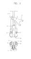
- FIG. 3 is a vertical sectional view showing a contact structure of a disconnecting switch in a gas insulating switchgear according to an embodiment of the present invention.
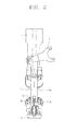
- FIG. 4 is an enlarged schematic view of an insulating screen unit of the contact structure in FIG. 3 .
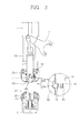
- FIGS. 5 and 6 are vertical sectional views showing contact structures in a closed circuit state and an open circuit state of the disconnecting switch in FIG. 3 , respectively;
- an upper conductor 1 and a lower conductor 2 are insulated and spaced apart by a certain interval from each other.
- a movable contact 110 is coupled tot a movable line 3 in the upper conductor 1 such that the movable contact 110 is movable linearly with respect to the upper conductor 1, and a fixed contact 210 is fixedly coupled to the lower conductor 2.
- a moving side tulip contact 120 is coupled to an end of the upper conductor 1, and a moving side shield 130 is installed at an outer side of the moving side tulip contact 120 to cover the moving side tulip contact 120 in order to prevent concentration of an electric field on the moving side tulip contact 120.
- the moving side shield 130 has a cylindrical shape with both ends thereof opened, and one opening end (referred to as a 'first opening end', hereinafter) (no reference numeral given) is fixedly inserted into a lower end of the upper conductor 1, and the other opening end (referred to as a 'second opening end', hereinafter) 131 of the moving side shield 130 is coupled to face the fixed contact 210.
- a contact insertion recess 111 having a certain depth is formed in the end of the movable contact 110 to allow the fixed contact 210 to be inserted therein.
- the fixed contact 210 is provided in the end of the lower conductor 2, and the fixed side tulip contact 220 is coupled in the vicinity of the fixed contact 210, and a fixed side shield 230 is installed at an outer side of the fixed side tulip contact 220 in order to prevent concentration of an electric field on the fixed side tulip contact 220.
- the driving unit operates in a direction the reverse to the case of the closed circuit and the movable contact 110 is rotated along with the movable link 3 in a direction the reverse to the direction of the case of the open circuit so as to slide linearly with respect to the upper conductor 1 and move upwardly to become distant from the fixed contact 210.
- the fixed contact 210 is separated to be spaced apart from the contact insertion recess 111 of the movable contact 110.
- the insulating screen unit may include an insulating screen 150 having a width sufficient for blocking the second opening end 131 of the moving side shield 130 and rotatably coupled within the moving side shield 130, a push link 160 slidably coupled to the insulating screen 150 and rotating the insulating screen 150 within a certain range, a support spring 170 supporting the push link 160 to press the push link 160 toward the fixed contact, a constraint pin 180 selectively restraining elastic force of the support spring 170 to selectively constrain the push link 160 to the movable contact 110, and a constraint spring 190 elastically supporting the constraint pin 180 horizontally toward the movable contact.
- the insulating screen 150 may be formed to have a fan-like shape.
- the insulating screen 150 may have a hinge portion 151 formed at a portion of a vertex and a blocking portion 152 formed at the other side of the hinge portion 151.
- the hinge portion 151 may be rotatably coupled to the moving side shield 130, and the blocking portion 152 may be formed to have a width sufficient for blocking the second opening end 131 of the moving side shield 130.
- a rotation recess 153 may be formed at one side of the insulating screen 150, namely, at one side between the hinge portion 151 and the blocking portion 152 such that a push pin 162 of the push link 160 slides to press the insulating screen 150.
- the push link 160 has a size by which the push link 160 may be movable within the moving side shield 130.
- a lower end of the support spring 170 is coupled to an upper end of the push link 160, and a stop portion 161 may be formed on a lower end of the push link 160 such that it is slidably inserted into the rotation recess 153 of the insulating screen 150.
- the push link 160 include a constraint recess 163 formed in a horizontal direction and having a certain depth to allow the constraint pin 180 and the constraint spring 190 to be inserted therein.
- the constraint recess 163 may be formed to be in the same horizontal line as a push recess 112 as described hereinafter when the movable contact 110 is completely separated from the fixed contact 210.
- the support spring 170 is configured as a compression coil spring such that one end thereof is supported by the moving side tulip contact 120 and the other end thereof is supported by the push link 160.
- the constraint pin 180 may be disposed such that it is inserted into the constraint recess 163 of the push link 160 and movable in a direction perpendicular to a movement direction of the movable contact 110, namely, in a horizontal direction, so as to be selectively inserted into the push recess 112 formed in a radial direction at one lateral side of the movable contact 110.
- the constraint pin 180 may have a length, a portion of which can be inserted into the push recess 112 of the movable contact 110 and another portion of which is inserted into the constraint recess 163 of the push link 160.
- the constraint recess 163 includes a stop surface 112a formed in the direction of the lower conductor 2 and a guide surface 112b formed to be sloped in the direction of the upper conductor 1.
- the constraint spring 190 is configured as a compression coil spring in order to elastically support the constraint pin toward the movable contact 110.
- the gas insulated switchgear according to an embodiment of the present invention has the following operational effects.
- the movable link 3 rotates in a counterclockwise direction in FIG. 5 .
- the movable contact 110 coupled to the movable link 3 is moved downwardly, escaping from the second opening end 131 of the moving side shield 130, and inserted into the fixed contact 210.
- the moving side tulip contact 120 is connected with the fixed side tulip contact 220 by the movable contact 110, thus completing a closing operation.
- the constraint pin 180 insertedly positioned in the push recess 112 of the movable contact 110 slides along the guide surface 112b of the push recess 112 so as to escape from the push recess 112.
- the push link 160 is free from the movable contact 110 and moves toward the fixed contact, namely, downwardly, by an elastic force of the support spring 170 until such time as the stopper 161 comes into contact with the second opening end 131 of the moving side shield 130.
- the push pin 162 of the push link 160 moves downwardly, it downwardly presses the rotation recess 153 which is eccentric with respect to the hinge portion 151 of the insulating screen 150.
- the insulating screen 150 is rotated in the clockwise direction based on the hinge portion 151 in the drawing, to open the second opening end 131 of the moving side shield 130. Then, the movable contact 110 passes through the opened second opening end 131 of the moving side shield 130 to move toward the fixed contact.
- the movable link 110 rotates in the clockwise direction in FIG. 6 . Then, the movable contact 110 coupled to the movable link 3 is separated from the fixed contact 210 and moves upwardly so as to be returned into the moving side shield 130, and as the moving side tulip contact 120 is separated from the fixed side tulip contact 220, the opening operation is completed.
- the constraint pin 180 is pushed by the constraint spring 190 and inserted into the push recess 112 of the movable contact 110 so as to be caught by the stop surface 112a.
- the constraint pin 180 moves upwardly along with the movable contact 110 to push the push link 160 upwardly.
- the push link 160 is moved upwardly to pressurize the support spring 170.
- the push pin 162 insertedly positioned in the rotation recess 153 of the insulating screen 150 is moved upwardly to rotate the insulating screen 150 in the counterclockwise direction in FIG. 6 , so the insulating screen 150 blocks the second opening end 131 of the moving side shield 130. Then, the space between the movable contact 110 and the fixed contact 210 is blocked by the insulating screen 150, thus preventing a concentration of an electric field to the movable contact 110 and the fixed contact 210.
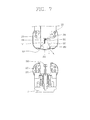
- FIG. 7 is a vertical sectional views showing another example of a contact structure of the disconnecting switch in the gas insulated switchgear according to an embodiment of the present invention.
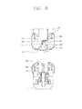
- FIGS. 8 and 9 are vertical sectional views showing contact structures in a closed circuit state and an open circuit state of the disconnecting switch in FIG. 7 , respectively.
- an insulating screen 250 may be configured such that a push surface 253 is formed to be sloped or rounded on an inner circumferential surface of a blocking portion 252.
- the push surface 253 may be formed to be in contact with a portion eccentric with respect to the center of the movable contact 110 in an axial direction.
- a hinge portion 251 may be formed at the center of the blocking portion 252 or formed to be eccentric toward a side in contact with the blocking portion 252.
- a return spring 260 may be coupled to the insulating screen 250 in order to return the insulating screen 250 when the movable contact 110 is returned to the moving side shield 130.
- the end of the movable contact 110 moves downwardly to push the blocking portion 252 of the insulating screen 250.
- the blocking portion 250 of the insulating screen 250 eccentrically in contact with the end surface of the movable contact 110 receives a pushing force from the movable contact 110, so the insulating screen 250 is rotated in a direction which is eccentric based on the hinge portion 251, namely, in the counterclockwise direction in the drawing.
- the insulating screen 250 is rotated in the second opening end 131 of the moving side shield 130, thus opening the second opening end 131.
- the movable contact 110 moves upwardly so as to be returned into the moving side shield 130, so the blocking portion 252 of the insulating screen 250 becomes free. Then, the return spring 260 is restored to rotate the insulating screen 250 in the clockwise direction in the drawing, thus blocking the second opening 131 of the moving side shield 130. Then, a space between the movable contact 110 and the fixed contact 210 is blocked by the insulating screen 250, thus preventing a concentration of an electric field on the movable contact 110 and the fixed contact 210.
- the insulating screen unit in the case of the closed circuit, when the movable contact moves toward the fixed contact, the insulating screen unit opens the opening end of the moving side shield, and in the case of the open circuit, when the movable contact is returned, the insulating screen unit blocks the opening end of the moving side shield.
Landscapes
- Engineering & Computer Science (AREA)
- Power Engineering (AREA)
- Gas-Insulated Switchgears (AREA)
Applications Claiming Priority (1)
| Application Number | Priority Date | Filing Date | Title |
|---|---|---|---|
| KR1020110073802A KR101771465B1 (ko) | 2011-07-25 | 2011-07-25 | 가스절연 개폐장치 |
Publications (3)
| Publication Number | Publication Date |
|---|---|
| EP2551876A2 true EP2551876A2 (fr) | 2013-01-30 |
| EP2551876A3 EP2551876A3 (fr) | 2014-10-15 |
| EP2551876B1 EP2551876B1 (fr) | 2016-01-06 |
Family
ID=46851800
Family Applications (1)
| Application Number | Title | Priority Date | Filing Date |
|---|---|---|---|
| EP12177439.2A Not-in-force EP2551876B1 (fr) | 2011-07-25 | 2012-07-23 | Installation de commutation isolée du gaz |
Country Status (6)
| Country | Link |
|---|---|
| US (1) | US8822867B2 (fr) |
| EP (1) | EP2551876B1 (fr) |
| KR (1) | KR101771465B1 (fr) |
| CN (1) | CN102904185B (fr) |
| ES (1) | ES2565934T3 (fr) |
| RU (1) | RU2516378C2 (fr) |
Families Citing this family (6)
| Publication number | Priority date | Publication date | Assignee | Title |
|---|---|---|---|---|
| JP2015060778A (ja) * | 2013-09-20 | 2015-03-30 | 株式会社東芝 | 開閉器 |
| US9842717B2 (en) * | 2015-05-29 | 2017-12-12 | Lsis Co., Ltd. | High speed closing switch |
| CN111799123B (zh) * | 2019-04-08 | 2023-01-03 | 河南平芝高压开关有限公司 | 一种静触头组件及使用该静触头组件的隔离开关 |
| CN110932159A (zh) * | 2019-12-05 | 2020-03-27 | 珠海康晋电气股份有限公司 | 气体绝缘开关柜 |
| CN112816865A (zh) * | 2021-04-19 | 2021-05-18 | 山东黄金电力有限公司 | 一种高压开关柜断路器动静触头接触行程测量装置 |
| EP4418295A1 (fr) * | 2023-02-14 | 2024-08-21 | General Electric Technology GmbH | Interrupteur rapide de mise à la terre mettant en oeuvre l'effet coanda |
Family Cites Families (24)
| Publication number | Priority date | Publication date | Assignee | Title |
|---|---|---|---|---|
| DE1465371B2 (de) * | 1964-05-27 | 1970-09-17 | Calor-Emag Elektrizitäts-AG, 4030 Ratingen | Kupplung für gaeisolierte Hochspannungsleitungen |
| FR2476381B1 (fr) * | 1980-02-16 | 1985-10-25 | Hitachi Ltd | Sectionneur isole par gaz |
| JPS59204406A (ja) | 1983-05-02 | 1984-11-19 | 株式会社日立製作所 | ガス絶縁開閉装置 |
| FR2563939B1 (fr) * | 1984-05-03 | 1988-03-18 | Telemecanique Electrique | Dispositif interrupteur a ecran de coupure d'arc |
| DE3770516D1 (de) * | 1986-04-04 | 1991-07-11 | Telemecanique Electrique | Elektrischer schalter fuer schutzgeraet, wie schutzschalter. |
| SU1345271A1 (ru) | 1986-08-18 | 1987-10-15 | Всесоюзный Электротехнический Институт Им.В.И.Ленина | Контактна система вакуумной дугогасительной камеры |
| DE3938711A1 (de) * | 1989-11-17 | 1991-05-23 | Siemens Ag | Trennschalter fuer metallgekapselte, druckgasisolierte hochspannungsschaltanlagen |
| SU1700628A1 (ru) | 1990-03-07 | 1991-12-23 | Всесоюзный Электротехнический Институт Им.В.И.Ленина | Контактна система вакуумной дугогасительной камеры |
| FR2667978B1 (fr) * | 1990-10-12 | 1997-07-18 | Sextant Avionique | Disjoncteur a ecran coupe-arc. |
| JPH04127921U (ja) * | 1991-05-15 | 1992-11-20 | 株式会社高岳製作所 | 開閉器の接触部 |
| JPH05199626A (ja) | 1992-01-20 | 1993-08-06 | Mitsubishi Electric Corp | ガス絶縁開閉器 |
| JP3202551B2 (ja) * | 1995-08-08 | 2001-08-27 | 株式会社日立製作所 | ガス遮断器 |
| JPH10155215A (ja) | 1996-11-25 | 1998-06-09 | Hitachi Ltd | ガス絶縁開閉装置 |
| KR100295905B1 (ko) | 1998-07-18 | 2001-08-07 | 이종수 | 진공인터럽터용전극구조체 |
| JP2000152445A (ja) * | 1998-11-09 | 2000-05-30 | Hitachi Ltd | ガス絶縁電気機器 |
| RU2178927C1 (ru) | 2000-06-19 | 2002-01-27 | Государственное унитарное предприятие "Всероссийский электротехнический институт им. В.И. Ленина" | Контактная система вакуумной дугогасительной камеры (варианты) |
| JP2002245907A (ja) | 2001-02-14 | 2002-08-30 | Hitachi Ltd | 真空バルブ用電極とその製法及び真空バルブ並びに真空遮断器と真空バルブ電極用電気接点 |
| JP4218216B2 (ja) * | 2001-02-22 | 2009-02-04 | 株式会社日立製作所 | ガス遮断器 |
| JP3876357B2 (ja) * | 2002-01-09 | 2007-01-31 | 株式会社日立製作所 | ガス遮断器 |
| US6965089B2 (en) | 2003-02-21 | 2005-11-15 | Mcgraw-Edison Company | Axial magnetic field vacuum fault interrupter |
| DE102006033766A1 (de) * | 2006-01-25 | 2007-07-26 | Abb Technology Ag | Kontaktanordnung für eine Kurzschließeinrichtung in einer Mittel- oder Hochspannungsschaltanlage |
| JP4908146B2 (ja) * | 2006-10-12 | 2012-04-04 | 株式会社東芝 | センサ付きicタグ適用高電圧機器 |
| KR100845107B1 (ko) * | 2006-12-29 | 2008-07-09 | 엘에스산전 주식회사 | 전력개폐장치 |
| EP2221844B1 (fr) * | 2009-02-24 | 2013-10-09 | ABB Technology AG | Dispositif de commutation |
-
2011
- 2011-07-25 KR KR1020110073802A patent/KR101771465B1/ko active Active
-
2012
- 2012-07-23 ES ES12177439.2T patent/ES2565934T3/es active Active
- 2012-07-23 US US13/556,113 patent/US8822867B2/en active Active
- 2012-07-23 EP EP12177439.2A patent/EP2551876B1/fr not_active Not-in-force
- 2012-07-24 RU RU2012131742/07A patent/RU2516378C2/ru active
- 2012-07-25 CN CN201210260838.5A patent/CN102904185B/zh active Active
Non-Patent Citations (1)
| Title |
|---|
| None |
Also Published As
| Publication number | Publication date |
|---|---|
| ES2565934T3 (es) | 2016-04-07 |
| EP2551876A3 (fr) | 2014-10-15 |
| US8822867B2 (en) | 2014-09-02 |
| KR101771465B1 (ko) | 2017-09-06 |
| RU2012131742A (ru) | 2014-01-27 |
| CN102904185B (zh) | 2015-07-01 |
| RU2516378C2 (ru) | 2014-05-20 |
| KR20130012522A (ko) | 2013-02-04 |
| EP2551876B1 (fr) | 2016-01-06 |
| US20130026138A1 (en) | 2013-01-31 |
| CN102904185A (zh) | 2013-01-30 |
Similar Documents
| Publication | Publication Date | Title |
|---|---|---|
| EP2551876B1 (fr) | Installation de commutation isolée du gaz | |
| EP2728603A1 (fr) | Interrupteur à trois voies pour appareil isolé au gaz | |
| JP2007014086A (ja) | 真空絶縁スイッチギヤ | |
| KR20180047430A (ko) | 단로기 연동조작형 진공부하개폐기 | |
| KR101686361B1 (ko) | 진공 차단기 | |
| EP2927926A1 (fr) | Appareillage de commutation de moyenne tension comprenant deux commutateurs par phase | |
| KR20240045173A (ko) | 가스절연 개폐장치의 전동 스프링 조작장치 | |
| JP2007014087A (ja) | 真空絶縁スイッチギヤ | |
| KR101678000B1 (ko) | 가스절연개폐장치 차단기의 이중동작 구조 | |
| CN108124493A (zh) | 开关装置和配电开关设备 | |
| KR101771464B1 (ko) | 가스절연개폐기의 접점장치 | |
| KR101697627B1 (ko) | 가스절연 개폐장치의 가스차단기 | |
| EP2474993A1 (fr) | Dispositif d'interruption de circuit et procédé d'assemblage | |
| KR20140106322A (ko) | 인입/인출형 고체절연 개폐장치 | |
| EP3441998A1 (fr) | Interrupteur | |
| KR101883432B1 (ko) | 보조스위치 일체형 진공차단기 | |
| KR100893766B1 (ko) | 개폐기의 스위치 접점 마모상태 표시기능을 갖는 친환경가스절연 수배전반 | |
| EP4459653B1 (fr) | Appareil de commutation pour systèmes électriques | |
| KR200406796Y1 (ko) | 가스절연개폐장치의 단로기 | |
| KR102871744B1 (ko) | 부하 차단 개폐기 | |
| KR200289430Y1 (ko) | 부하 개폐기 | |
| KR101034555B1 (ko) | 변전설비 차단기용 액츄에이터 | |
| US10784659B2 (en) | Switchgear with removable circuit interrupter configuration | |
| KR200177082Y1 (ko) | 가스절연 개폐기의 인터록장치 | |
| JP2016163499A (ja) | 開閉装置 |
Legal Events
| Date | Code | Title | Description |
|---|---|---|---|
| PUAI | Public reference made under article 153(3) epc to a published international application that has entered the european phase |
Free format text: ORIGINAL CODE: 0009012 |
|
| AK | Designated contracting states |
Kind code of ref document: A2 Designated state(s): AL AT BE BG CH CY CZ DE DK EE ES FI FR GB GR HR HU IE IS IT LI LT LU LV MC MK MT NL NO PL PT RO RS SE SI SK SM TR |
|
| AX | Request for extension of the european patent |
Extension state: BA ME |
|
| PUAL | Search report despatched |
Free format text: ORIGINAL CODE: 0009013 |
|
| AK | Designated contracting states |
Kind code of ref document: A3 Designated state(s): AL AT BE BG CH CY CZ DE DK EE ES FI FR GB GR HR HU IE IS IT LI LT LU LV MC MK MT NL NO PL PT RO RS SE SI SK SM TR |
|
| AX | Request for extension of the european patent |
Extension state: BA ME |
|
| RIC1 | Information provided on ipc code assigned before grant |
Ipc: H01H 33/06 20060101ALI20140908BHEP Ipc: H01H 33/24 20060101ALI20140908BHEP Ipc: H01H 31/32 20060101AFI20140908BHEP |
|
| 17P | Request for examination filed |
Effective date: 20150330 |
|
| RBV | Designated contracting states (corrected) |
Designated state(s): AL AT BE BG CH CY CZ DE DK EE ES FI FR GB GR HR HU IE IS IT LI LT LU LV MC MK MT NL NO PL PT RO RS SE SI SK SM TR |
|
| GRAP | Despatch of communication of intention to grant a patent |
Free format text: ORIGINAL CODE: EPIDOSNIGR1 |
|
| INTG | Intention to grant announced |
Effective date: 20150722 |
|
| RAP1 | Party data changed (applicant data changed or rights of an application transferred) |
Owner name: LSIS CO., LTD. |
|
| GRAS | Grant fee paid |
Free format text: ORIGINAL CODE: EPIDOSNIGR3 |
|
| GRAA | (expected) grant |
Free format text: ORIGINAL CODE: 0009210 |
|
| AK | Designated contracting states |
Kind code of ref document: B1 Designated state(s): AL AT BE BG CH CY CZ DE DK EE ES FI FR GB GR HR HU IE IS IT LI LT LU LV MC MK MT NL NO PL PT RO RS SE SI SK SM TR |
|
| REG | Reference to a national code |
Ref country code: GB Ref legal event code: FG4D |
|
| REG | Reference to a national code |
Ref country code: CH Ref legal event code: EP |
|
| REG | Reference to a national code |
Ref country code: IE Ref legal event code: FG4D |
|
| REG | Reference to a national code |
Ref country code: AT Ref legal event code: REF Ref document number: 769488 Country of ref document: AT Kind code of ref document: T Effective date: 20160215 |
|
| REG | Reference to a national code |
Ref country code: DE Ref legal event code: R096 Ref document number: 602012013584 Country of ref document: DE |
|
| REG | Reference to a national code |
Ref country code: ES Ref legal event code: FG2A Ref document number: 2565934 Country of ref document: ES Kind code of ref document: T3 Effective date: 20160407 |
|
| REG | Reference to a national code |
Ref country code: LT Ref legal event code: MG4D |
|
| REG | Reference to a national code |
Ref country code: NL Ref legal event code: MP Effective date: 20160106 |
|
| REG | Reference to a national code |
Ref country code: AT Ref legal event code: MK05 Ref document number: 769488 Country of ref document: AT Kind code of ref document: T Effective date: 20160106 |
|
| REG | Reference to a national code |
Ref country code: FR Ref legal event code: PLFP Year of fee payment: 5 |
|
| PG25 | Lapsed in a contracting state [announced via postgrant information from national office to epo] |
Ref country code: NL Free format text: LAPSE BECAUSE OF FAILURE TO SUBMIT A TRANSLATION OF THE DESCRIPTION OR TO PAY THE FEE WITHIN THE PRESCRIBED TIME-LIMIT Effective date: 20160106 |
|
| PG25 | Lapsed in a contracting state [announced via postgrant information from national office to epo] |
Ref country code: GR Free format text: LAPSE BECAUSE OF FAILURE TO SUBMIT A TRANSLATION OF THE DESCRIPTION OR TO PAY THE FEE WITHIN THE PRESCRIBED TIME-LIMIT Effective date: 20160407 Ref country code: NO Free format text: LAPSE BECAUSE OF FAILURE TO SUBMIT A TRANSLATION OF THE DESCRIPTION OR TO PAY THE FEE WITHIN THE PRESCRIBED TIME-LIMIT Effective date: 20160406 Ref country code: HR Free format text: LAPSE BECAUSE OF FAILURE TO SUBMIT A TRANSLATION OF THE DESCRIPTION OR TO PAY THE FEE WITHIN THE PRESCRIBED TIME-LIMIT Effective date: 20160106 Ref country code: FI Free format text: LAPSE BECAUSE OF FAILURE TO SUBMIT A TRANSLATION OF THE DESCRIPTION OR TO PAY THE FEE WITHIN THE PRESCRIBED TIME-LIMIT Effective date: 20160106 |
|
| PG25 | Lapsed in a contracting state [announced via postgrant information from national office to epo] |
Ref country code: AT Free format text: LAPSE BECAUSE OF FAILURE TO SUBMIT A TRANSLATION OF THE DESCRIPTION OR TO PAY THE FEE WITHIN THE PRESCRIBED TIME-LIMIT Effective date: 20160106 Ref country code: RS Free format text: LAPSE BECAUSE OF FAILURE TO SUBMIT A TRANSLATION OF THE DESCRIPTION OR TO PAY THE FEE WITHIN THE PRESCRIBED TIME-LIMIT Effective date: 20160106 Ref country code: SE Free format text: LAPSE BECAUSE OF FAILURE TO SUBMIT A TRANSLATION OF THE DESCRIPTION OR TO PAY THE FEE WITHIN THE PRESCRIBED TIME-LIMIT Effective date: 20160106 Ref country code: IS Free format text: LAPSE BECAUSE OF FAILURE TO SUBMIT A TRANSLATION OF THE DESCRIPTION OR TO PAY THE FEE WITHIN THE PRESCRIBED TIME-LIMIT Effective date: 20160506 Ref country code: PT Free format text: LAPSE BECAUSE OF FAILURE TO SUBMIT A TRANSLATION OF THE DESCRIPTION OR TO PAY THE FEE WITHIN THE PRESCRIBED TIME-LIMIT Effective date: 20160506 Ref country code: PL Free format text: LAPSE BECAUSE OF FAILURE TO SUBMIT A TRANSLATION OF THE DESCRIPTION OR TO PAY THE FEE WITHIN THE PRESCRIBED TIME-LIMIT Effective date: 20160106 Ref country code: LV Free format text: LAPSE BECAUSE OF FAILURE TO SUBMIT A TRANSLATION OF THE DESCRIPTION OR TO PAY THE FEE WITHIN THE PRESCRIBED TIME-LIMIT Effective date: 20160106 Ref country code: LT Free format text: LAPSE BECAUSE OF FAILURE TO SUBMIT A TRANSLATION OF THE DESCRIPTION OR TO PAY THE FEE WITHIN THE PRESCRIBED TIME-LIMIT Effective date: 20160106 |
|
| REG | Reference to a national code |
Ref country code: DE Ref legal event code: R097 Ref document number: 602012013584 Country of ref document: DE |
|
| PG25 | Lapsed in a contracting state [announced via postgrant information from national office to epo] |
Ref country code: EE Free format text: LAPSE BECAUSE OF FAILURE TO SUBMIT A TRANSLATION OF THE DESCRIPTION OR TO PAY THE FEE WITHIN THE PRESCRIBED TIME-LIMIT Effective date: 20160106 Ref country code: DK Free format text: LAPSE BECAUSE OF FAILURE TO SUBMIT A TRANSLATION OF THE DESCRIPTION OR TO PAY THE FEE WITHIN THE PRESCRIBED TIME-LIMIT Effective date: 20160106 |
|
| PLBE | No opposition filed within time limit |
Free format text: ORIGINAL CODE: 0009261 |
|
| STAA | Information on the status of an ep patent application or granted ep patent |
Free format text: STATUS: NO OPPOSITION FILED WITHIN TIME LIMIT |
|
| PG25 | Lapsed in a contracting state [announced via postgrant information from national office to epo] |
Ref country code: CZ Free format text: LAPSE BECAUSE OF FAILURE TO SUBMIT A TRANSLATION OF THE DESCRIPTION OR TO PAY THE FEE WITHIN THE PRESCRIBED TIME-LIMIT Effective date: 20160106 Ref country code: RO Free format text: LAPSE BECAUSE OF FAILURE TO SUBMIT A TRANSLATION OF THE DESCRIPTION OR TO PAY THE FEE WITHIN THE PRESCRIBED TIME-LIMIT Effective date: 20160106 Ref country code: SK Free format text: LAPSE BECAUSE OF FAILURE TO SUBMIT A TRANSLATION OF THE DESCRIPTION OR TO PAY THE FEE WITHIN THE PRESCRIBED TIME-LIMIT Effective date: 20160106 Ref country code: SM Free format text: LAPSE BECAUSE OF FAILURE TO SUBMIT A TRANSLATION OF THE DESCRIPTION OR TO PAY THE FEE WITHIN THE PRESCRIBED TIME-LIMIT Effective date: 20160106 |
|
| 26N | No opposition filed |
Effective date: 20161007 |
|
| PG25 | Lapsed in a contracting state [announced via postgrant information from national office to epo] |
Ref country code: BE Free format text: LAPSE BECAUSE OF FAILURE TO SUBMIT A TRANSLATION OF THE DESCRIPTION OR TO PAY THE FEE WITHIN THE PRESCRIBED TIME-LIMIT Effective date: 20160106 |
|
| PG25 | Lapsed in a contracting state [announced via postgrant information from national office to epo] |
Ref country code: SI Free format text: LAPSE BECAUSE OF FAILURE TO SUBMIT A TRANSLATION OF THE DESCRIPTION OR TO PAY THE FEE WITHIN THE PRESCRIBED TIME-LIMIT Effective date: 20160106 Ref country code: BG Free format text: LAPSE BECAUSE OF FAILURE TO SUBMIT A TRANSLATION OF THE DESCRIPTION OR TO PAY THE FEE WITHIN THE PRESCRIBED TIME-LIMIT Effective date: 20160406 |
|
| REG | Reference to a national code |
Ref country code: CH Ref legal event code: PL |
|
| PG25 | Lapsed in a contracting state [announced via postgrant information from national office to epo] |
Ref country code: MC Free format text: LAPSE BECAUSE OF FAILURE TO SUBMIT A TRANSLATION OF THE DESCRIPTION OR TO PAY THE FEE WITHIN THE PRESCRIBED TIME-LIMIT Effective date: 20160106 |
|
| PG25 | Lapsed in a contracting state [announced via postgrant information from national office to epo] |
Ref country code: LI Free format text: LAPSE BECAUSE OF NON-PAYMENT OF DUE FEES Effective date: 20160731 Ref country code: CH Free format text: LAPSE BECAUSE OF NON-PAYMENT OF DUE FEES Effective date: 20160731 |
|
| REG | Reference to a national code |
Ref country code: IE Ref legal event code: MM4A |
|
| REG | Reference to a national code |
Ref country code: FR Ref legal event code: PLFP Year of fee payment: 6 |
|
| PG25 | Lapsed in a contracting state [announced via postgrant information from national office to epo] |
Ref country code: IE Free format text: LAPSE BECAUSE OF NON-PAYMENT OF DUE FEES Effective date: 20160723 |
|
| PG25 | Lapsed in a contracting state [announced via postgrant information from national office to epo] |
Ref country code: LU Free format text: LAPSE BECAUSE OF NON-PAYMENT OF DUE FEES Effective date: 20160723 |
|
| PG25 | Lapsed in a contracting state [announced via postgrant information from national office to epo] |
Ref country code: CY Free format text: LAPSE BECAUSE OF FAILURE TO SUBMIT A TRANSLATION OF THE DESCRIPTION OR TO PAY THE FEE WITHIN THE PRESCRIBED TIME-LIMIT Effective date: 20160106 Ref country code: HU Free format text: LAPSE BECAUSE OF FAILURE TO SUBMIT A TRANSLATION OF THE DESCRIPTION OR TO PAY THE FEE WITHIN THE PRESCRIBED TIME-LIMIT; INVALID AB INITIO Effective date: 20120723 |
|
| REG | Reference to a national code |
Ref country code: FR Ref legal event code: PLFP Year of fee payment: 7 |
|
| PG25 | Lapsed in a contracting state [announced via postgrant information from national office to epo] |
Ref country code: MK Free format text: LAPSE BECAUSE OF FAILURE TO SUBMIT A TRANSLATION OF THE DESCRIPTION OR TO PAY THE FEE WITHIN THE PRESCRIBED TIME-LIMIT Effective date: 20160106 Ref country code: TR Free format text: LAPSE BECAUSE OF FAILURE TO SUBMIT A TRANSLATION OF THE DESCRIPTION OR TO PAY THE FEE WITHIN THE PRESCRIBED TIME-LIMIT Effective date: 20160106 Ref country code: MT Free format text: LAPSE BECAUSE OF NON-PAYMENT OF DUE FEES Effective date: 20160731 |
|
| PG25 | Lapsed in a contracting state [announced via postgrant information from national office to epo] |
Ref country code: AL Free format text: LAPSE BECAUSE OF FAILURE TO SUBMIT A TRANSLATION OF THE DESCRIPTION OR TO PAY THE FEE WITHIN THE PRESCRIBED TIME-LIMIT Effective date: 20160106 |
|
| PGFP | Annual fee paid to national office [announced via postgrant information from national office to epo] |
Ref country code: FR Payment date: 20200609 Year of fee payment: 9 |
|
| PGFP | Annual fee paid to national office [announced via postgrant information from national office to epo] |
Ref country code: GB Payment date: 20200608 Year of fee payment: 9 |
|
| PGFP | Annual fee paid to national office [announced via postgrant information from national office to epo] |
Ref country code: ES Payment date: 20200807 Year of fee payment: 9 Ref country code: DE Payment date: 20200605 Year of fee payment: 9 |
|
| PGFP | Annual fee paid to national office [announced via postgrant information from national office to epo] |
Ref country code: IT Payment date: 20200713 Year of fee payment: 9 |
|
| REG | Reference to a national code |
Ref country code: DE Ref legal event code: R119 Ref document number: 602012013584 Country of ref document: DE |
|
| GBPC | Gb: european patent ceased through non-payment of renewal fee |
Effective date: 20210723 |
|
| PG25 | Lapsed in a contracting state [announced via postgrant information from national office to epo] |
Ref country code: GB Free format text: LAPSE BECAUSE OF NON-PAYMENT OF DUE FEES Effective date: 20210723 Ref country code: DE Free format text: LAPSE BECAUSE OF NON-PAYMENT OF DUE FEES Effective date: 20220201 |
|
| PG25 | Lapsed in a contracting state [announced via postgrant information from national office to epo] |
Ref country code: FR Free format text: LAPSE BECAUSE OF NON-PAYMENT OF DUE FEES Effective date: 20210731 |
|
| PG25 | Lapsed in a contracting state [announced via postgrant information from national office to epo] |
Ref country code: IT Free format text: LAPSE BECAUSE OF NON-PAYMENT OF DUE FEES Effective date: 20210723 |
|
| REG | Reference to a national code |
Ref country code: ES Ref legal event code: FD2A Effective date: 20220930 |
|
| PG25 | Lapsed in a contracting state [announced via postgrant information from national office to epo] |
Ref country code: ES Free format text: LAPSE BECAUSE OF NON-PAYMENT OF DUE FEES Effective date: 20210724 |