EP2551969A1 - Boîte de jonction pour conduites électriques et système de répartition électrique avec des boîtes de jonction de ce type - Google Patents
Boîte de jonction pour conduites électriques et système de répartition électrique avec des boîtes de jonction de ce type Download PDFInfo
- Publication number
- EP2551969A1 EP2551969A1 EP12172113A EP12172113A EP2551969A1 EP 2551969 A1 EP2551969 A1 EP 2551969A1 EP 12172113 A EP12172113 A EP 12172113A EP 12172113 A EP12172113 A EP 12172113A EP 2551969 A1 EP2551969 A1 EP 2551969A1
- Authority
- EP
- European Patent Office
- Prior art keywords
- housing
- distributor box
- electrical
- contact body
- line
- Prior art date
- Legal status (The legal status is an assumption and is not a legal conclusion. Google has not performed a legal analysis and makes no representation as to the accuracy of the status listed.)
- Granted
Links
- 239000004020 conductor Substances 0.000 claims abstract description 37
- 238000009826 distribution Methods 0.000 claims abstract description 34
- 238000005520 cutting process Methods 0.000 claims description 5
- 238000003825 pressing Methods 0.000 claims description 4
- 239000011810 insulating material Substances 0.000 claims description 3
- 150000001875 compounds Chemical class 0.000 claims description 2
- 230000007547 defect Effects 0.000 claims description 2
- 238000009413 insulation Methods 0.000 claims description 2
- 239000000126 substance Substances 0.000 abstract 1
- 238000002955 isolation Methods 0.000 description 4
- 238000004519 manufacturing process Methods 0.000 description 3
- 230000015572 biosynthetic process Effects 0.000 description 2
- 238000010276 construction Methods 0.000 description 2
- 238000011144 upstream manufacturing Methods 0.000 description 2
- 230000006978 adaptation Effects 0.000 description 1
- 230000000295 complement effect Effects 0.000 description 1
- 238000010616 electrical installation Methods 0.000 description 1
- 238000009472 formulation Methods 0.000 description 1
- 238000009434 installation Methods 0.000 description 1
- 239000000203 mixture Substances 0.000 description 1
Images



Classifications
-
- H—ELECTRICITY
- H01—ELECTRIC ELEMENTS
- H01R—ELECTRICALLY-CONDUCTIVE CONNECTIONS; STRUCTURAL ASSOCIATIONS OF A PLURALITY OF MUTUALLY-INSULATED ELECTRICAL CONNECTING ELEMENTS; COUPLING DEVICES; CURRENT COLLECTORS
- H01R25/00—Coupling parts adapted for simultaneous co-operation with two or more identical counterparts, e.g. for distributing energy to two or more circuits
- H01R25/16—Rails or bus-bars provided with a plurality of discrete connecting locations for counterparts
- H01R25/168—Rails or bus-bars provided with a plurality of discrete connecting locations for counterparts the connecting locations being situated away from the rail or bus-bar
-
- H—ELECTRICITY
- H02—GENERATION; CONVERSION OR DISTRIBUTION OF ELECTRIC POWER
- H02G—INSTALLATION OF ELECTRIC CABLES OR LINES, OR OF COMBINED OPTICAL AND ELECTRIC CABLES OR LINES
- H02G3/00—Installations of electric cables or lines or protective tubing therefor in or on buildings, equivalent structures or vehicles
- H02G3/02—Details
- H02G3/08—Distribution boxes; Connection or junction boxes
- H02G3/081—Bases, casings or covers
- H02G3/083—Inlets
-
- H—ELECTRICITY
- H02—GENERATION; CONVERSION OR DISTRIBUTION OF ELECTRIC POWER
- H02G—INSTALLATION OF ELECTRIC CABLES OR LINES, OR OF COMBINED OPTICAL AND ELECTRIC CABLES OR LINES
- H02G3/00—Installations of electric cables or lines or protective tubing therefor in or on buildings, equivalent structures or vehicles
- H02G3/02—Details
- H02G3/08—Distribution boxes; Connection or junction boxes
- H02G3/088—Dustproof, splashproof, drip-proof, waterproof, or flameproof casings or inlets
-
- H—ELECTRICITY
- H02—GENERATION; CONVERSION OR DISTRIBUTION OF ELECTRIC POWER
- H02G—INSTALLATION OF ELECTRIC CABLES OR LINES, OR OF COMBINED OPTICAL AND ELECTRIC CABLES OR LINES
- H02G3/00—Installations of electric cables or lines or protective tubing therefor in or on buildings, equivalent structures or vehicles
- H02G3/02—Details
- H02G3/08—Distribution boxes; Connection or junction boxes
- H02G3/14—Fastening of cover or lid to box
-
- H—ELECTRICITY
- H02—GENERATION; CONVERSION OR DISTRIBUTION OF ELECTRIC POWER
- H02G—INSTALLATION OF ELECTRIC CABLES OR LINES, OR OF COMBINED OPTICAL AND ELECTRIC CABLES OR LINES
- H02G3/00—Installations of electric cables or lines or protective tubing therefor in or on buildings, equivalent structures or vehicles
- H02G3/02—Details
- H02G3/08—Distribution boxes; Connection or junction boxes
- H02G3/16—Distribution boxes; Connection or junction boxes structurally associated with support for line-connecting terminals within the box
-
- H—ELECTRICITY
- H01—ELECTRIC ELEMENTS
- H01R—ELECTRICALLY-CONDUCTIVE CONNECTIONS; STRUCTURAL ASSOCIATIONS OF A PLURALITY OF MUTUALLY-INSULATED ELECTRICAL CONNECTING ELEMENTS; COUPLING DEVICES; CURRENT COLLECTORS
- H01R4/00—Electrically-conductive connections between two or more conductive members in direct contact, i.e. touching one another; Means for effecting or maintaining such contact; Electrically-conductive connections having two or more spaced connecting locations for conductors and using contact members penetrating insulation
- H01R4/24—Connections using contact members penetrating or cutting insulation or cable strands
Definitions
- the present invention relates to a distribution box for electrical lines, comprising a housing consisting of an insulating material, which has input and output side through openings for the electrical lines, comprising two interconnectable housing parts, namely a bottom part and a cover part, and arranged with a housing , electrically conductive contact body with connection points for the conductors of the electrical lines. Furthermore, the present invention relates to an electrical distribution system with such distribution boxes.
- Distribution boxes - also called splitters or distribution blocks - of the type mentioned are always used in electrical installations where an electrical potential is to be forwarded to several points. These may be so-called multi-series splitters, in which case in the case of the connection of three electrical lines to a box of so-called Y-connectors or Y-splitters speaks.
- Y-connectors or Y-splitters speaks.
- star distributors and distribution blocks with a number of permanently configured slots are known in the prior art. Since in these devices all lines to a central point, are disadvantageously required for connecting to the distribution boxes lines long lengths.
- a distribution box of the type mentioned is z. B. from the German utility model DE 20 2011 000 244 U1 known.
- the distributor block described there has on the input side on a connection side to a first and a second connection point, which allow each as a passage openings in a housing the detachable connection of an electrical conductor and are superimposed in two planes.
- the utility model relates in particular to a special design of the terminals, wherein in the interior of the housing consisting of a lower housing part and a housing upper part housing as a contact body, a clamping body and to a movable fixing part are provided.
- the first and second connection point in the distribution block can be electrically connected.
- the distributor block On the output side, the distributor block also has lead-through openings in the housing, it being possible with the aid of clamping screws to connect electrical conductors which lead to other electrical devices or units.
- the known distribution block is very voluminous and has a bottom profile for releasable connection to a mounting element.
- the assembly by means of the clamping screws is relatively complex and requires in addition to the lead-through openings for the conductor further housing breakthroughs. A high degree of tightness or a high degree of protection can therefore not be achieved.
- the present invention has for its object to provide a Verteilerbox of the type mentioned, which allows it with little manufacturing and assembly effort to build a location-independent electrical contact system for configuring a variable current path, preferably for series-connected current-conducting circuit applications.
- the aforementioned disadvantages should be overcome.
- this object is achieved in that the passage openings are arranged in at least one of the housing parts and are designed as each closed by the other housing part open-edged recesses of the wall of the housing part.
- distributor box it is possible to configure electrical circuits by chaining and / or network formation flexibly and location-independently in a simple manner and using lines shorter compared with the known devices for line branching, wherein at least two distributor boxes according to the invention can be produced in such an inventive electrical distribution system are interconnected by at least one electrical line.
- the electrically conductive contact body is formed in several parts, wherein electrical bridge elements, such as rotary or rotary switch, foldable contact tabs, jumpers, jumper parts o. ⁇ . May be provided by the polarity of one or multiple connection points is changeable.
- An arrangement of all lead-through openings in the bottom part of the housing and its design as closable by the lid part open-edged recesses of the wall of the bottom part and preferably an embodiment of the cover part of interconnected segments and with separate closability of the recesses in the bottom part through the cover part segments allows a very simple Production method of the housing, for example as a one- or two-part injection-molded part, and a low-effort installation.
- latching elements can be arranged on the bottom part and on the cover part of the housing for mutual latching of the two housing parts which can be connected to one another.
- connection points of the contact body are screwless systems, such as clamping, cutting or plug contact systems, by means of which the head of the electrical wires to be connected automatically contacted by pressing and the lines are preferably cut through before.
- the inventive electrical distribution box or the distribution system according to the invention can be used as components of lights or control gear boxes or their respective interfaces.
- the electrical distribution box according to the invention with advantage, for example, as a configurable terminal for connecting one or more consumers, in particular of several series-connected, constant current-consuming high-power LEDs, are used, wherein the distributor box, the electrical connections between a supply line, the consumer and a continuing electrical line or an upstream electronics manufactures.
- the connection points can be connected in such a way that each light source is connected in series with other light sources of the same circuit, but if necessary, also group or parallel circuits can be configured.
- FIG. 1 and 2 illustrate, a distributor box according to the invention 1 for electrical lines 2, 3, 4 of an insulating material existing housing 5 on.
- This housing 5 comprises two housing parts 6, 7 which can be connected to one another, namely a bottom part 6 and a cover part 7.
- the housing 5 has through openings 8, 9, 10 for the electrical lines 2, 3, 4.
- an electrically conductive contact body 11 with connection points 12, 13, 14, 15, 16, 17 for the conductors 18, 19, 20, 21, 22, 23 of the electrical lines 2, 3, 4 to be connected is arranged.
- the housing 5 has a parallelepipedic basic shape, preferably a cuboidal basic shape, and has bevelled corner areas.
- three lead-through openings 8, 9, 10 are provided corresponding to the number of electrical lines 2, 3, 4 to be connected.
- the distributor box 1 according to the invention is therefore a Y-connector or Y-brancher.
- a lead-through opening 8 is arranged in each case on one end face, a further lead-through opening 9 on the opposite end face and a third lead-through opening 10 on a longitudinal side of the bottom part 6.
- cover part 7 are designed as closable by the cover part 7 open-edged recesses of the wall of the bottom part 6, wherein the cover part 7 of interconnected segments 7a, 7b, 7c and each recess can be closed separately by a segment 7a, 7b, 7c of the cover part 7 assigned to it.
- the segments 7a, 7b, 7c of the cover part 7 are connected to each other via hinges 70a, 70b, in particular via film hinges, whereby the cover part 7 is preferably formed in one piece.
- the lid part 7 is connected via a further hinge 70c, in particular again - as shown - via a film hinge at a central segment 70b of the cover part 7 with the bottom part 6, wherein the cover part 7 and the bottom part 6 is preferably formed in one piece are.
- the cover part 7 is thereby advantageously held captive on the bottom part 6 and can be produced together with this as a single housing component.
- compared to a two-part design which is also possible, without further measures increases the tightness of the housing 5 in the region of the film hinge.
- the latching elements on the bottom part 6, which are preferably openings in the housing wall, are unitary with the reference numeral 24, the latching elements on the cover part 7, which are preferably latching hooks on each of the segments 70a, 70b, 70c are uniformly designated by the reference numeral 25.
- the locking elements 24, 25 ensure easy closeability and a simple way to open the housing 5 and can be made directly in the manufacture of the housing 5 as integrally molded hooks 25 or molded openings 24 in a low-effort manner.
- the distributor box 1 advantageously allows the connection points 12, 13, 14, 15, 16, 17 of the contact body 11 to be designed as screwless systems, such as clamping, cutting or plug-in contact systems.
- the conductors 18, 19, 20, 21, 22, 23 of the electrical lines 2, 3, 4 to be connected can be contacted automatically by pressing on the contact body 11.
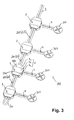
- Fig. 3 As shown in the illustration of an electrical distribution system 100 according to the invention, such a construction results from the fact that at least two distributor boxes 1 according to the invention are connected to one another by at least one electrical connection line 200.
- connecting lines 200 can in.
- Fig. 1 and 4 to 6 each with the reference numerals 2 and 3 designated lines occur, while at the designated by the reference numeral 4 electrical line in each case an electrical load 300 is connected.
- the distributor box 1 according to the invention can produce the electrical connections between a supply line 3, the loads 300 and a continuative electrical line 2 or also an upstream electronics.
- the connection points 12, 13, 14, 15, 16, 17, the electrically conductive contact body 11 are configured in the distribution boxes 1 such that connected in an electrical circuit with a supply line and at least two consumers, the load in series are.
- connection points 12, 13, 14, 15, 16, 17 of the contact body 11 for two conductors 18, 19, 20, 21, 22, 23 at least one electrical line 2, 3, 4 by means of a in one Distribution box 1 integrated or connected foldable conductor bridge 2a are electrically sealed, as this Fig. 3 shows.
- Fig. 3 not as such, but this is the case when the contact bodies 11 of the distribution boxes 1 used to make the circuit are configured as such Fig. 1 such as 4 to 6 demonstrate. It can be seen there that the contact bodies 11 are made in several parts, in this case in three parts, wherein the individual parts 11a, 11b, 11c are separated from one another by insulating webs 27a, 27b, 27c. The insulating webs 27a, 27b, 27c are part of a single insulating body 27 in an assembly-friendly design.
- the first part 11a of the contact body 11 connects a first conductor 18 of the first line 2 and a first conductor 20 of the second line 3.
- the second part 11b of the contact body 11 connects a second conductor 19 of the first line 2 and a first conductor 22 of the third Line 4.
- the third part 11 c of the contact body 11 connects a second conductor 23 of the third line 4 and a second conductor 21 of the second line 3.
- the first part 11 a and the second part 11 b of the contact body 11 are separated from each other by the first insulating web 27a separated.
- the first part 11a and the third part 11c of the contact body 11 are separated from each other by the second insulating land 27b.
- the second part 11 b and the third part 11 c of the contact body 11 are separated from each other by the third insulating web 27 c.
- the conductors 18, 19, 20, 21, 22, 23 are assigned their respective contact points 12, 13, 14, 15, 16, 17, to which the parts 11 a, 11 b, 11 c of the contact body are electrically connected.
- Fig. 5 illustrated second embodiment and in Fig. 6 illustrated third embodiment of a distributor box 1 according to the invention differ from the first embodiment, as the connection points 12, 13, 14, 15, 16, 17 of the contact body 11 through the conductors 18, 19, 20, 21, 22, 23 of the electrical lines to be connected 2, 3, 4 are contacted. All versions are consistent with screwless systems in which the conductors 18, 19, 20, 21, 22, 23 are contacted automatically by pressing, but is in Fig. 1 and 4 a cutting system, in Fig. 5 for the conductors 22, 23 of the line leading to the consumer 300 4 a system with a connection via tab 26 on each conductor 22 23 and in Fig.
- the housing 5 could also be designed with a triangular ground plan with feedthrough openings 8, 9, 10 offset by 120 ° from one another.
- a spherical housing design is possible without departing from the scope of the invention.
- connection points 12, 13, 14, 15, 16, 17 indicating elements are connected to the electrically conductive contact body 11.
- At least one electrical or electronic bypass such as a diode, be integrated, which in case of a defect of a connected Consumer, such as an LED light source, bridges the current running through the consumer current path. In this way it can be avoided that in case of failure of a consumer immediately the entire circuit fails.
- strain-relieving devices into the housing 5 for the electrical lines 2, 3, 4 to be connected.
- the conductors 18, 19, 20, 21, 22, 23 of the electrical lines 2, 3, 4 to be connected in the housing 5, at least at their connection points 12, 13, 14, 15 , 16, 17, are encapsulated in a watertight manner, wherein preferably at least the bottom part 6 of the housing 5 is filled with an insulating compound.
- the invention is not limited to the feature combinations defined in claims 1 and 21, but may also be defined by any other combination of particular features of all individually disclosed features. This means that in principle virtually every individual feature of the independent claims can be omitted or replaced by at least one individual feature disclosed elsewhere in the application. In this respect, the claims are to be understood merely as a first formulation attempt for an invention.
Landscapes
- Engineering & Computer Science (AREA)
- Architecture (AREA)
- Civil Engineering (AREA)
- Structural Engineering (AREA)
- Connection Or Junction Boxes (AREA)
Applications Claiming Priority (1)
| Application Number | Priority Date | Filing Date | Title |
|---|---|---|---|
| DE201120050826 DE202011050826U1 (de) | 2011-07-27 | 2011-07-27 | Verteilerbox für elektrische Leitungen und elektrisches Verteilersystem mit derartigen Verteilerboxen |
Publications (2)
| Publication Number | Publication Date |
|---|---|
| EP2551969A1 true EP2551969A1 (fr) | 2013-01-30 |
| EP2551969B1 EP2551969B1 (fr) | 2015-08-05 |
Family
ID=46318968
Family Applications (1)
| Application Number | Title | Priority Date | Filing Date |
|---|---|---|---|
| EP12172113.8A Not-in-force EP2551969B1 (fr) | 2011-07-27 | 2012-06-15 | Boîte de jonction pour conduites électriques et système de répartition électrique avec des boîtes de jonction de ce type |
Country Status (3)
| Country | Link |
|---|---|
| EP (1) | EP2551969B1 (fr) |
| DE (1) | DE202011050826U1 (fr) |
| ES (1) | ES2552508T3 (fr) |
Families Citing this family (1)
| Publication number | Priority date | Publication date | Assignee | Title |
|---|---|---|---|---|
| DE102018117906B4 (de) * | 2018-07-24 | 2021-01-07 | Christoph Mühlhans | Verteilervorrichtung und System zum Führen und Verteilen von elektrischer Energie und zum Bereitstellen einer datenleitenden Kommunikationsverbindung |
Citations (4)
| Publication number | Priority date | Publication date | Assignee | Title |
|---|---|---|---|---|
| GB432237A (en) * | 1934-05-12 | 1935-07-23 | Henleys Telegraph Works Co Ltd | Improvements in electric junction boxes |
| DE722208C (de) * | 1936-11-17 | 1942-07-04 | Kaiser & Spelsberg | Duennwandige Unterputz-Abzweigdose aus Kunstharz-Warmpressstoff mit seitlichen Leitungseinfuehrungsstutzen |
| EP1355398A2 (fr) * | 2002-04-16 | 2003-10-22 | ARNOULD Fabrique d'Appareillage Electrique | Système électrique à connexion rapide |
| DE102008022055A1 (de) * | 2008-05-03 | 2009-11-05 | Lumberg Connect Gmbh | Anschlussdose für ein Solarmodul |
Family Cites Families (1)
| Publication number | Priority date | Publication date | Assignee | Title |
|---|---|---|---|---|
| DE202011000244U1 (de) | 2011-02-02 | 2011-03-31 | Hora-Werk Gmbh | Verteilerblock |
-
2011
- 2011-07-27 DE DE201120050826 patent/DE202011050826U1/de not_active Expired - Lifetime
-
2012
- 2012-06-15 EP EP12172113.8A patent/EP2551969B1/fr not_active Not-in-force
- 2012-06-15 ES ES12172113.8T patent/ES2552508T3/es active Active
Patent Citations (4)
| Publication number | Priority date | Publication date | Assignee | Title |
|---|---|---|---|---|
| GB432237A (en) * | 1934-05-12 | 1935-07-23 | Henleys Telegraph Works Co Ltd | Improvements in electric junction boxes |
| DE722208C (de) * | 1936-11-17 | 1942-07-04 | Kaiser & Spelsberg | Duennwandige Unterputz-Abzweigdose aus Kunstharz-Warmpressstoff mit seitlichen Leitungseinfuehrungsstutzen |
| EP1355398A2 (fr) * | 2002-04-16 | 2003-10-22 | ARNOULD Fabrique d'Appareillage Electrique | Système électrique à connexion rapide |
| DE102008022055A1 (de) * | 2008-05-03 | 2009-11-05 | Lumberg Connect Gmbh | Anschlussdose für ein Solarmodul |
Also Published As
| Publication number | Publication date |
|---|---|
| DE202011050826U1 (de) | 2012-10-29 |
| EP2551969B1 (fr) | 2015-08-05 |
| ES2552508T3 (es) | 2015-11-30 |
Similar Documents
| Publication | Publication Date | Title |
|---|---|---|
| EP2255410B1 (fr) | Barrette a bornes ou bloc de barrettes a bornes | |
| DE69816236T2 (de) | Schnittstellenvorrichtung zwischen Teilen einer Anlage | |
| DE19964156A1 (de) | Elektrisches Gerät | |
| DE102008050322B4 (de) | Elektromotor-Anschluss sowie Elektromotor | |
| EP2790272A2 (fr) | Installation de répartition de courant ainsi que sa mise en contact et la protection des lignes qui en sortent | |
| DE202014101491U1 (de) | Busfähiges aneinanderreihbares Anschluss- und/oder Funktionsmodul | |
| EP2091113B1 (fr) | Système de raccordement pour bandes lumineuses ou lampes | |
| DE102016224327A1 (de) | Anordnung mit intern konfigurierbarer Festkörperschalteranordnung zur Verwendung als ein oder mehrere Trennschalter in elektrischen Systemen und mit externer gemeinsamer Verpackung mit den elektrischen Systemen | |
| EP3607614B1 (fr) | Procédé de réalisation d'un câblage sur une matrice composée de dispositifs de raccordement | |
| EP2856561B1 (fr) | Borne de raccordement électrique | |
| EP2551969B1 (fr) | Boîte de jonction pour conduites électriques et système de répartition électrique avec des boîtes de jonction de ce type | |
| WO2017178372A1 (fr) | Distributeur de courant pour un réseau de bord de véhicule et réseau de bord de véhicule associé | |
| DE102004043468A1 (de) | Schaltgerät mit steckbaren Anschlüssen | |
| EP0918369A2 (fr) | Dispositif de raccordement de conducteurs électriques | |
| DE19630202C2 (de) | Leitungsverzweiger | |
| WO2006027338A1 (fr) | Module d'entree de courant | |
| EP3827483B1 (fr) | Dispositif de distribution et système d'acheminement et de distribution de l'énergie électrique et de fourniture d'une connexion de communication communiquant des données | |
| DE19700057C2 (de) | Datenschiene für den Europäischen Installationsbus (EIB) | |
| EP1941589B1 (fr) | Module de connexion avec borne de contact de type perce-isolant | |
| DE102018106003A1 (de) | Anschlussklemme | |
| DE102017011369A1 (de) | Würfelstecker, insbesondere für ein elektromechanisches Hydraulikventil, sowie unter Einschluss desselben aufgebautes Hydrauliksystem | |
| EP2701243B1 (fr) | Dispositif de raccordement, notamment pour une soupape hydraulique électromécanique et système hydraulique conçu de manière à intégrer celle-ci | |
| DE102005005082B4 (de) | Elektrische Verbindungsvorrichtung und Verfahren zur Verbindung von elektrischen Leitern sowie elektrisches Leitungssystem | |
| CH719094B1 (de) | Anschlusseinrichtung mit Nullleitertrennung für ein Kabelanschlusskasten. | |
| DE102024131163A1 (de) | Anschlussklemmenmodul und damit gebildete Anschlussklemmenanordnung |
Legal Events
| Date | Code | Title | Description |
|---|---|---|---|
| PUAI | Public reference made under article 153(3) epc to a published international application that has entered the european phase |
Free format text: ORIGINAL CODE: 0009012 |
|
| AK | Designated contracting states |
Kind code of ref document: A1 Designated state(s): AL AT BE BG CH CY CZ DE DK EE ES FI FR GB GR HR HU IE IS IT LI LT LU LV MC MK MT NL NO PL PT RO RS SE SI SK SM TR |
|
| AX | Request for extension of the european patent |
Extension state: BA ME |
|
| 17P | Request for examination filed |
Effective date: 20130726 |
|
| RBV | Designated contracting states (corrected) |
Designated state(s): AL AT BE BG CH CY CZ DE DK EE ES FI FR GB GR HR HU IE IS IT LI LT LU LV MC MK MT NL NO PL PT RO RS SE SI SK SM TR |
|
| 17Q | First examination report despatched |
Effective date: 20140716 |
|
| GRAP | Despatch of communication of intention to grant a patent |
Free format text: ORIGINAL CODE: EPIDOSNIGR1 |
|
| INTG | Intention to grant announced |
Effective date: 20150211 |
|
| GRAS | Grant fee paid |
Free format text: ORIGINAL CODE: EPIDOSNIGR3 |
|
| GRAA | (expected) grant |
Free format text: ORIGINAL CODE: 0009210 |
|
| AK | Designated contracting states |
Kind code of ref document: B1 Designated state(s): AL AT BE BG CH CY CZ DE DK EE ES FI FR GB GR HR HU IE IS IT LI LT LU LV MC MK MT NL NO PL PT RO RS SE SI SK SM TR |
|
| REG | Reference to a national code |
Ref country code: GB Ref legal event code: FG4D Free format text: NOT ENGLISH |
|
| REG | Reference to a national code |
Ref country code: CH Ref legal event code: EP |
|
| REG | Reference to a national code |
Ref country code: AT Ref legal event code: REF Ref document number: 741165 Country of ref document: AT Kind code of ref document: T Effective date: 20150815 |
|
| REG | Reference to a national code |
Ref country code: IE Ref legal event code: FG4D Free format text: LANGUAGE OF EP DOCUMENT: GERMAN |
|
| REG | Reference to a national code |
Ref country code: NL Ref legal event code: T3 |
|
| REG | Reference to a national code |
Ref country code: DE Ref legal event code: R096 Ref document number: 502012004010 Country of ref document: DE |
|
| REG | Reference to a national code |
Ref country code: ES Ref legal event code: FG2A Ref document number: 2552508 Country of ref document: ES Kind code of ref document: T3 Effective date: 20151130 |
|
| REG | Reference to a national code |
Ref country code: LT Ref legal event code: MG4D |
|
| PG25 | Lapsed in a contracting state [announced via postgrant information from national office to epo] |
Ref country code: FI Free format text: LAPSE BECAUSE OF FAILURE TO SUBMIT A TRANSLATION OF THE DESCRIPTION OR TO PAY THE FEE WITHIN THE PRESCRIBED TIME-LIMIT Effective date: 20150805 Ref country code: LV Free format text: LAPSE BECAUSE OF FAILURE TO SUBMIT A TRANSLATION OF THE DESCRIPTION OR TO PAY THE FEE WITHIN THE PRESCRIBED TIME-LIMIT Effective date: 20150805 Ref country code: GR Free format text: LAPSE BECAUSE OF FAILURE TO SUBMIT A TRANSLATION OF THE DESCRIPTION OR TO PAY THE FEE WITHIN THE PRESCRIBED TIME-LIMIT Effective date: 20151106 Ref country code: LT Free format text: LAPSE BECAUSE OF FAILURE TO SUBMIT A TRANSLATION OF THE DESCRIPTION OR TO PAY THE FEE WITHIN THE PRESCRIBED TIME-LIMIT Effective date: 20150805 Ref country code: NO Free format text: LAPSE BECAUSE OF FAILURE TO SUBMIT A TRANSLATION OF THE DESCRIPTION OR TO PAY THE FEE WITHIN THE PRESCRIBED TIME-LIMIT Effective date: 20151105 |
|
| PG25 | Lapsed in a contracting state [announced via postgrant information from national office to epo] |
Ref country code: SE Free format text: LAPSE BECAUSE OF FAILURE TO SUBMIT A TRANSLATION OF THE DESCRIPTION OR TO PAY THE FEE WITHIN THE PRESCRIBED TIME-LIMIT Effective date: 20150805 Ref country code: PT Free format text: LAPSE BECAUSE OF FAILURE TO SUBMIT A TRANSLATION OF THE DESCRIPTION OR TO PAY THE FEE WITHIN THE PRESCRIBED TIME-LIMIT Effective date: 20151207 Ref country code: RS Free format text: LAPSE BECAUSE OF FAILURE TO SUBMIT A TRANSLATION OF THE DESCRIPTION OR TO PAY THE FEE WITHIN THE PRESCRIBED TIME-LIMIT Effective date: 20150805 Ref country code: IS Free format text: LAPSE BECAUSE OF FAILURE TO SUBMIT A TRANSLATION OF THE DESCRIPTION OR TO PAY THE FEE WITHIN THE PRESCRIBED TIME-LIMIT Effective date: 20151205 Ref country code: HR Free format text: LAPSE BECAUSE OF FAILURE TO SUBMIT A TRANSLATION OF THE DESCRIPTION OR TO PAY THE FEE WITHIN THE PRESCRIBED TIME-LIMIT Effective date: 20150805 Ref country code: PL Free format text: LAPSE BECAUSE OF FAILURE TO SUBMIT A TRANSLATION OF THE DESCRIPTION OR TO PAY THE FEE WITHIN THE PRESCRIBED TIME-LIMIT Effective date: 20150805 |
|
| PG25 | Lapsed in a contracting state [announced via postgrant information from national office to epo] |
Ref country code: SK Free format text: LAPSE BECAUSE OF FAILURE TO SUBMIT A TRANSLATION OF THE DESCRIPTION OR TO PAY THE FEE WITHIN THE PRESCRIBED TIME-LIMIT Effective date: 20150805 Ref country code: CZ Free format text: LAPSE BECAUSE OF FAILURE TO SUBMIT A TRANSLATION OF THE DESCRIPTION OR TO PAY THE FEE WITHIN THE PRESCRIBED TIME-LIMIT Effective date: 20150805 Ref country code: DK Free format text: LAPSE BECAUSE OF FAILURE TO SUBMIT A TRANSLATION OF THE DESCRIPTION OR TO PAY THE FEE WITHIN THE PRESCRIBED TIME-LIMIT Effective date: 20150805 Ref country code: EE Free format text: LAPSE BECAUSE OF FAILURE TO SUBMIT A TRANSLATION OF THE DESCRIPTION OR TO PAY THE FEE WITHIN THE PRESCRIBED TIME-LIMIT Effective date: 20150805 |
|
| REG | Reference to a national code |
Ref country code: DE Ref legal event code: R097 Ref document number: 502012004010 Country of ref document: DE |
|
| PG25 | Lapsed in a contracting state [announced via postgrant information from national office to epo] |
Ref country code: RO Free format text: LAPSE BECAUSE OF FAILURE TO SUBMIT A TRANSLATION OF THE DESCRIPTION OR TO PAY THE FEE WITHIN THE PRESCRIBED TIME-LIMIT Effective date: 20150805 |
|
| PLBE | No opposition filed within time limit |
Free format text: ORIGINAL CODE: 0009261 |
|
| STAA | Information on the status of an ep patent application or granted ep patent |
Free format text: STATUS: NO OPPOSITION FILED WITHIN TIME LIMIT |
|
| REG | Reference to a national code |
Ref country code: FR Ref legal event code: PLFP Year of fee payment: 5 |
|
| 26N | No opposition filed |
Effective date: 20160509 |
|
| PG25 | Lapsed in a contracting state [announced via postgrant information from national office to epo] |
Ref country code: SI Free format text: LAPSE BECAUSE OF FAILURE TO SUBMIT A TRANSLATION OF THE DESCRIPTION OR TO PAY THE FEE WITHIN THE PRESCRIBED TIME-LIMIT Effective date: 20150805 |
|
| PG25 | Lapsed in a contracting state [announced via postgrant information from national office to epo] |
Ref country code: BE Free format text: LAPSE BECAUSE OF NON-PAYMENT OF DUE FEES Effective date: 20160630 |
|
| PG25 | Lapsed in a contracting state [announced via postgrant information from national office to epo] |
Ref country code: MC Free format text: LAPSE BECAUSE OF FAILURE TO SUBMIT A TRANSLATION OF THE DESCRIPTION OR TO PAY THE FEE WITHIN THE PRESCRIBED TIME-LIMIT Effective date: 20150805 |
|
| REG | Reference to a national code |
Ref country code: CH Ref legal event code: PL |
|
| REG | Reference to a national code |
Ref country code: IE Ref legal event code: MM4A |
|
| PG25 | Lapsed in a contracting state [announced via postgrant information from national office to epo] |
Ref country code: CH Free format text: LAPSE BECAUSE OF NON-PAYMENT OF DUE FEES Effective date: 20160630 Ref country code: LI Free format text: LAPSE BECAUSE OF NON-PAYMENT OF DUE FEES Effective date: 20160630 |
|
| PG25 | Lapsed in a contracting state [announced via postgrant information from national office to epo] |
Ref country code: IE Free format text: LAPSE BECAUSE OF NON-PAYMENT OF DUE FEES Effective date: 20160615 |
|
| REG | Reference to a national code |
Ref country code: FR Ref legal event code: PLFP Year of fee payment: 6 |
|
| PGFP | Annual fee paid to national office [announced via postgrant information from national office to epo] |
Ref country code: NL Payment date: 20170628 Year of fee payment: 6 Ref country code: AT Payment date: 20170710 Year of fee payment: 6 |
|
| PGFP | Annual fee paid to national office [announced via postgrant information from national office to epo] |
Ref country code: TR Payment date: 20170529 Year of fee payment: 6 |
|
| PGFP | Annual fee paid to national office [announced via postgrant information from national office to epo] |
Ref country code: IT Payment date: 20170628 Year of fee payment: 6 Ref country code: ES Payment date: 20170801 Year of fee payment: 6 |
|
| PG25 | Lapsed in a contracting state [announced via postgrant information from national office to epo] |
Ref country code: HU Free format text: LAPSE BECAUSE OF FAILURE TO SUBMIT A TRANSLATION OF THE DESCRIPTION OR TO PAY THE FEE WITHIN THE PRESCRIBED TIME-LIMIT; INVALID AB INITIO Effective date: 20120615 Ref country code: SM Free format text: LAPSE BECAUSE OF FAILURE TO SUBMIT A TRANSLATION OF THE DESCRIPTION OR TO PAY THE FEE WITHIN THE PRESCRIBED TIME-LIMIT Effective date: 20150805 Ref country code: CY Free format text: LAPSE BECAUSE OF FAILURE TO SUBMIT A TRANSLATION OF THE DESCRIPTION OR TO PAY THE FEE WITHIN THE PRESCRIBED TIME-LIMIT Effective date: 20150805 |
|
| REG | Reference to a national code |
Ref country code: FR Ref legal event code: PLFP Year of fee payment: 7 |
|
| PG25 | Lapsed in a contracting state [announced via postgrant information from national office to epo] |
Ref country code: LU Free format text: LAPSE BECAUSE OF NON-PAYMENT OF DUE FEES Effective date: 20160615 Ref country code: MK Free format text: LAPSE BECAUSE OF FAILURE TO SUBMIT A TRANSLATION OF THE DESCRIPTION OR TO PAY THE FEE WITHIN THE PRESCRIBED TIME-LIMIT Effective date: 20150805 Ref country code: MT Free format text: LAPSE BECAUSE OF FAILURE TO SUBMIT A TRANSLATION OF THE DESCRIPTION OR TO PAY THE FEE WITHIN THE PRESCRIBED TIME-LIMIT Effective date: 20150805 |
|
| PG25 | Lapsed in a contracting state [announced via postgrant information from national office to epo] |
Ref country code: BG Free format text: LAPSE BECAUSE OF FAILURE TO SUBMIT A TRANSLATION OF THE DESCRIPTION OR TO PAY THE FEE WITHIN THE PRESCRIBED TIME-LIMIT Effective date: 20150805 |
|
| PG25 | Lapsed in a contracting state [announced via postgrant information from national office to epo] |
Ref country code: AL Free format text: LAPSE BECAUSE OF FAILURE TO SUBMIT A TRANSLATION OF THE DESCRIPTION OR TO PAY THE FEE WITHIN THE PRESCRIBED TIME-LIMIT Effective date: 20150805 |
|
| REG | Reference to a national code |
Ref country code: NL Ref legal event code: MM Effective date: 20180701 |
|
| REG | Reference to a national code |
Ref country code: AT Ref legal event code: MM01 Ref document number: 741165 Country of ref document: AT Kind code of ref document: T Effective date: 20180615 |
|
| PG25 | Lapsed in a contracting state [announced via postgrant information from national office to epo] |
Ref country code: NL Free format text: LAPSE BECAUSE OF NON-PAYMENT OF DUE FEES Effective date: 20180701 |
|
| PG25 | Lapsed in a contracting state [announced via postgrant information from national office to epo] |
Ref country code: AT Free format text: LAPSE BECAUSE OF NON-PAYMENT OF DUE FEES Effective date: 20180615 Ref country code: IT Free format text: LAPSE BECAUSE OF NON-PAYMENT OF DUE FEES Effective date: 20180615 |
|
| REG | Reference to a national code |
Ref country code: ES Ref legal event code: FD2A Effective date: 20190916 |
|
| PG25 | Lapsed in a contracting state [announced via postgrant information from national office to epo] |
Ref country code: ES Free format text: LAPSE BECAUSE OF NON-PAYMENT OF DUE FEES Effective date: 20180616 |
|
| REG | Reference to a national code |
Ref country code: DE Ref legal event code: R082 Ref document number: 502012004010 Country of ref document: DE Representative=s name: DR. SOLF & ZAPF PATENT- UND RECHTSANWAELTE, DE Ref country code: DE Ref legal event code: R082 Ref document number: 502012004010 Country of ref document: DE Representative=s name: DR. SOLF & ZAPF PATENT- UND RECHTSANWALTS PART, DE |
|
| PG25 | Lapsed in a contracting state [announced via postgrant information from national office to epo] |
Ref country code: TR Free format text: LAPSE BECAUSE OF NON-PAYMENT OF DUE FEES Effective date: 20180615 |
|
| PGFP | Annual fee paid to national office [announced via postgrant information from national office to epo] |
Ref country code: FR Payment date: 20230522 Year of fee payment: 12 |
|
| PGFP | Annual fee paid to national office [announced via postgrant information from national office to epo] |
Ref country code: GB Payment date: 20230519 Year of fee payment: 12 |
|
| PGFP | Annual fee paid to national office [announced via postgrant information from national office to epo] |
Ref country code: DE Payment date: 20230828 Year of fee payment: 12 |
|
| REG | Reference to a national code |
Ref country code: DE Ref legal event code: R119 Ref document number: 502012004010 Country of ref document: DE |
|
| GBPC | Gb: european patent ceased through non-payment of renewal fee |
Effective date: 20240615 |
|
| PG25 | Lapsed in a contracting state [announced via postgrant information from national office to epo] |
Ref country code: DE Free format text: LAPSE BECAUSE OF NON-PAYMENT OF DUE FEES Effective date: 20250101 |
|
| PG25 | Lapsed in a contracting state [announced via postgrant information from national office to epo] |
Ref country code: FR Free format text: LAPSE BECAUSE OF NON-PAYMENT OF DUE FEES Effective date: 20240630 |
|
| PG25 | Lapsed in a contracting state [announced via postgrant information from national office to epo] |
Ref country code: GB Free format text: LAPSE BECAUSE OF NON-PAYMENT OF DUE FEES Effective date: 20240615 |