EP2551993B1 - Elektromagnet für einen stator und herstellungsverfahren des elektromagnets für einen stator - Google Patents
Elektromagnet für einen stator und herstellungsverfahren des elektromagnets für einen stator Download PDFInfo
- Publication number
- EP2551993B1 EP2551993B1 EP11759165.1A EP11759165A EP2551993B1 EP 2551993 B1 EP2551993 B1 EP 2551993B1 EP 11759165 A EP11759165 A EP 11759165A EP 2551993 B1 EP2551993 B1 EP 2551993B1
- Authority
- EP
- European Patent Office
- Prior art keywords
- winding
- line material
- notch
- stator
- flange
- Prior art date
- Legal status (The legal status is an assumption and is not a legal conclusion. Google has not performed a legal analysis and makes no representation as to the accuracy of the status listed.)
- Active
Links
Images


Classifications
-
- H—ELECTRICITY
- H02—GENERATION; CONVERSION OR DISTRIBUTION OF ELECTRIC POWER
- H02K—DYNAMO-ELECTRIC MACHINES
- H02K3/00—Details of windings
- H02K3/46—Fastening of windings on the stator or rotor structure
- H02K3/52—Fastening salient pole windings or connections thereto
- H02K3/521—Fastening salient pole windings or connections thereto applicable to stators only
- H02K3/522—Fastening salient pole windings or connections thereto applicable to stators only for generally annular cores with salient poles
-
- H—ELECTRICITY
- H02—GENERATION; CONVERSION OR DISTRIBUTION OF ELECTRIC POWER
- H02K—DYNAMO-ELECTRIC MACHINES
- H02K15/00—Processes or apparatus specially adapted for manufacturing, assembling, maintaining or repairing of dynamo-electric machines
- H02K15/04—Processes or apparatus specially adapted for manufacturing, assembling, maintaining or repairing of dynamo-electric machines of windings prior to their mounting into the machines
- H02K15/043—Processes or apparatus specially adapted for manufacturing, assembling, maintaining or repairing of dynamo-electric machines of windings prior to their mounting into the machines winding flat conductive wires or sheets
- H02K15/0431—Concentrated windings
-
- H—ELECTRICITY
- H02—GENERATION; CONVERSION OR DISTRIBUTION OF ELECTRIC POWER
- H02K—DYNAMO-ELECTRIC MACHINES
- H02K15/00—Processes or apparatus specially adapted for manufacturing, assembling, maintaining or repairing of dynamo-electric machines
- H02K15/30—Manufacture of winding connections
- H02K15/33—Connecting winding sections; Forming leads; Connecting leads to terminals
- H02K15/35—Form-wound windings
-
- H—ELECTRICITY
- H02—GENERATION; CONVERSION OR DISTRIBUTION OF ELECTRIC POWER
- H02K—DYNAMO-ELECTRIC MACHINES
- H02K2203/00—Specific aspects not provided for in the other groups of this subclass relating to the windings
- H02K2203/06—Machines characterised by the wiring leads, i.e. conducting wires for connecting the winding terminations
-
- H—ELECTRICITY
- H02—GENERATION; CONVERSION OR DISTRIBUTION OF ELECTRIC POWER
- H02K—DYNAMO-ELECTRIC MACHINES
- H02K2203/00—Specific aspects not provided for in the other groups of this subclass relating to the windings
- H02K2203/12—Machines characterised by the bobbins for supporting the windings
-
- Y—GENERAL TAGGING OF NEW TECHNOLOGICAL DEVELOPMENTS; GENERAL TAGGING OF CROSS-SECTIONAL TECHNOLOGIES SPANNING OVER SEVERAL SECTIONS OF THE IPC; TECHNICAL SUBJECTS COVERED BY FORMER USPC CROSS-REFERENCE ART COLLECTIONS [XRACs] AND DIGESTS
- Y10—TECHNICAL SUBJECTS COVERED BY FORMER USPC
- Y10T—TECHNICAL SUBJECTS COVERED BY FORMER US CLASSIFICATION
- Y10T29/00—Metal working
- Y10T29/49—Method of mechanical manufacture
- Y10T29/49002—Electrical device making
- Y10T29/4902—Electromagnet, transformer or inductor
Definitions
- the present invention relates to an electromagnet used for a stator of an electric motor or a generator and a manufacturing method thereof.
- JP2008-236854 A published by Japan Patent Office in 2008 proposes an electromagnet for a stator of an electric motor or a generator.
- This electromagnet for a stator is provided with a stator core formed of a back yoke and teeth projecting from the back yoke toward the center of the stator.
- An insulator is attached to an outer periphery of each tooth.
- the insulator has a winding barrel around which a coil is wound. Flanges are formed at respective ends of the winding barrel, one on a tooth base end side in the vicinity of the back yoke and another one on a tooth distal end side.
- a notch is formed in the flange on the tooth base end side.
- a line material of a coil is guided to the winding barrel from the outside of the flange on the tooth base end side through the notch.
- US 2009/243420 A1 discloses a rotational motor that includes a stator formed by a core member including: a magnetic core portion extending in a radial direction of the rotational motor and formed into a fixed shape in every cross section thereof extending orthogonally relative to the radial direction, a coil wound around the magnetic core portion to form a plurality of layers and an engagement member engaging with the coil.
- US 2006/087192 A1 discloses a switched reluctance machine that includes a stator body having a stator pole. A bobbin is located on the stator pole. A stator winding is disposed on the bobbin.
- US 2006/087192 A1 discloses an electric machine that includes a segmented or non-segmented stator and an end shield defining at least one opening therein.
- the machine also includes at least one winding having a lead end and an exit end, and at least one end cap coupled to the stator.
- the end cap defines first and second grooves which are respectively engaged with either the lead end or exit end of the winding. The end cap guides the lead and exit ends through the opening in the end shield.
- the line material When the coil line material is to be guided to the winding barrel from the outside of the flange on the tooth base end side through the notch, the line material is guided from an opening part of the notch to the inside of the notch in a state where the line material is oblique to a flange surface so that the line material does not interfere with the flanges on the both sides of the notch. At this time, if the line material is easily bent, the line material interferes with the flange, which might make it difficult to guide the line material to the notch. This interference between the line material and the flange lowers efficiency of a coiling work on the insulator and lowers positioning accuracy of a coiling start position of the winding on the winding barrel.
- the electromagnet comprises a stator core formed of a back yoke and a tooth projecting from the back yoke, an insulator attached to the tooth, and a coil wound around the insulator.
- the insulator comprises a winding barrel around which a coil is wound in a plurality of layers, a first flange formed at one end of the winding barrel and having a notch through which a coil line material passes, and a second flange formed at another end of the winding barrel. Projecting lengths of the first flange from the winding barrel on the both sides of the notch are set to be different from each other.
- a stator 1 is a collective name of a plurality of electromagnets 2 arranged around a rotor of an electric motor or a generator in which permanent magnets are arranged.
- the rotor In the electric motor, the rotor is rotated around a center axis by feeding power to coils so as to magnetize the electromagnets.
- the electromagnets In the generator, the electromagnets generate an electric current in the coils by means of relative rotation between the rotor and the stator 1 around the center axis.
- the stator 1 comprises a plurality of stator cores 10 connected in the circumferential direction around the center axis.
- the stator core 10 is made of a back yoke 11 and a tooth 12 projecting toward the center axis direction from the back yoke 11.
- the stator core 10 is constructed by laminating thin electromagnetic steel plates punched substantially in the T-shape.
- the laminated electromagnetic steel plates are integrated by dwell caulking or welding, for example, so that they do not separate from each other.
- a projection 11A is formed on a side face of the back yoke 11.
- a recess 11B is formed on another side face of the back yoke 11. The projection 11A fits in the recess 11B of an adjacent stator core 10.
- the tooth 12 comprises a main body 121 and a distal end part 122.
- the distal end part 122 is formed at a distal end of the main body 121 and has an enlarged width to form a tapered shape.
- Distal end faces of the teeth 12 form a circular shape around the center axis. These distal end faces represent magnetic poles of the electromagnets opposing the rotor.
- an insulator 20 is provided with a cylindrical winding barrel 21 attached to the outer periphery of the tooth 12 of the stator core 10.
- a first flange 22 in contact with the back yoke 11 is formed at one end on the back yoke 11 side of the winding barrel 21.
- a second flange 23 is formed so as to surround the distal end part 122 of the tooth 12 on the other end of the winding barrel 21.
- the insulator 20 is formed of an insulator such as a resin.
- a line material 40 of a coil is wound around the outer periphery of the winding barrel 21 with normal winding, for example, as shown in Fig. 8 .
- the flanges 22 and 23 on the both ends of the winding barrel 21 regulate the winding width of each winding layer of the line material 40 of the coil. In other words, the flanges 22 and 23 prevent protrusion of the coil to the outside of the insulator 20.
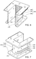
- the insulator 20 is made of a first component 20A shown in Figs. 3 and 4 and a second component 20B shown in Figs. 6 and 7 which are split in the laminating direction of the electromagnetic steel plate of the stator core 10, for the purpose of fitting onto the tooth 12.
- the first component 20A and the second component 20B are engaged with each other to cover the tooth 12 from the both sides thereof in the direction of the center axis of the stator 1.
- the first component 20A comprises a winding-barrel element 21A having a U-shaped cross-section, a flange element 22A formed at one end on the back yoke 11 side of the winding-barrel element 21A, and a flange element 23A formed at another end of the winding-barrel element 21A, which is farther from the back yoke 11.
- the second component 20B comprises a winding-barrel element 21B having a U-shaped cross-section, a flange element 22B formed at one end on the back yoke 11 side of the winding-barrel element 21B, and a flange element 23B formed at another end of the winding-barrel element 21B, which is farther from the back yoke 11.
- split structure of the insulator 20 a split structure other than the above-described split structure such as splitting the insulator 20 in a direction orthogonal to the laminating direction of the electromagnetic steel plates of the stator core 10, or in other words, splitting the insulator 20 in a circumferential direction of the stator core 10 is also possible. Moreover, splitting the insulator 20 into three to four elements at arbitrary split positions on the outer periphery of the tooth 12 is also possible.
- the first component 20A and the second component 20B when in an engaged state, form the cylindrical winding barrel 21 covering the tooth 12, the first flange 22 provided at the end of the back yoke 11 side of the winding barrel 21, and the second flange 23 provided at the another end of the winding barrel 21, which is farther from the back yoke 11.
- two band-shaped projections 24A and 24B are formed in the winding direction on one of the side faces directed to the connecting direction of the stator core 10 of the winding-barrel element 21A of the first component 20A.
- a single band-shaped projection 24C is formed in the winding direction.
- the formation position of the band-shaped projection 24C with respect to the radial direction of the stator 1 corresponds to the position between the formation positions of the band-shaped projection 24A and the band-shaped projection 24B.
- Plural parallel grooves 26A are formed in the radial direction of the stator 1 on a bottom surface 26 of the winding-barrel element 21A in contact with the end face of the tooth 12 with respect to the center axis direction of the stator 1.
- a thin fitting part 25A is formed in engaging parts of the winding-barrel element 21A, the flange element 22A, and the flange element 23A with the second component 20B.
- the thin fitting part 25A is formed by retreating a surface of the winding-barrel element 21A facing the tooth 12, a surface of the flange element 22A facing the back yoke 11, and a surface of the flange element 23A facing the distal end part 122 of the tooth 12 over a predetermined length, respectively.
- a tab 26B projecting outward in the radial direction of the stator 1 over a predetermined distance is fixed to the flange element 22A.
- the tab 26B defines, as shown in Fig. 1 , relative positions of the stator core 10 and the insulator 20 in the center axis direction of the stator 1 by being brought into contact with one of the end faces of the back yoke 11 with respect to the center axis direction of the stator 1.
- a rectangular notch 27 is formed for drawing a winding start part and a winding end part of the coil line material 40 that is wound around the outer periphery of the winding barrel 21 from the winding barrel 21 to the outside of the first flange 22.
- the notch 27 is formed in a part of the flange element 22A projecting from the stator core 1 in the center axis direction of the stator 1.
- a first portion 28A located on one side of the notch 27 and a second portion 28B located on an opposite side of the of the notch 27 to the first portion 28A are formed.
- the notch 27 and the first portion 28A and the second portion 28B of the flange element 22A are both located farther than the tab 26B from the winding barrel 21 in the center axis direction of the stator 1.
- the first portion 28A comprises a winding start positioning projection 30 abutting on the notch 27 and projecting outward in the radial direction of the stator 1.
- a first groove 31 is formed on the opposite side of the winding start positioning projection 30 to the notch 27.
- a guide surface 29 for guiding the line material 40 to the notch 27 through a space between the winding start positioning projection 30/first groove 31 and the tab 26B is formed in the first portion 28A.
- the guide surface 29 is formed as a slope inclined with respect to a bottom side of the notch 27 in order to smoothly guide the line material 40 when the line material 40 is introduced from the outside of the first flange 22 to the winding barrel 21 through the notch 27.
- the winding start positioning projection 30 performs positioning and locking by bending the winding start part of the line material 40 at the end of winding on the winding barrel 21.
- the first groove 31 prevents displacement of the winding start part of the line material 40 from the positioning position and also plays a role of locking the winding start part of the line material 40.
- the second portion 28B comprises a winding end positioning projection 33 abutting on the notch 27 and projecting outward in the radial direction of the stator 1.
- a second groove 34 is formed on the opposite side of the winding end positioning projection 33 to the notch 27.
- a notch 35 is formed in the winding end positioning projection 33 at a part opposing the tab 26B.
- the winding end positioning projection 33 performs positioning and locking by bending the winding end part of the line material 40 at the end of winding on the winding barrel 21.
- the notch 35 formed in the winding end positioning projection 33 prevents loosening of the line material 40 by holding the line material 40 in the bent state.
- the second groove 34 prevents displacement of the winding end part of the line material 40 from the positioning position and also plays a role of locking the winding end part of the line material 40.
- a projecting length L1 of the first portion 28A from the winding barrel 21 with respect to the axial direction of the stator 1 is set longer than a projecting length L2 of the second portion 28B from the winding barrel 21 with respect to the same direction.
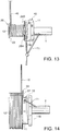
- Such setting facilitates an operation of bending the line material 40 towards the winding barrel 21 by using the first portion 28A as a fulcrum when the line material 40 is guided to the winding barrel 21 from the outside of the first flange 22 through the notch 27 as shown in Fig. 11 .
- a corner part 30A facing the notch 27 of the first portion 28A is preferably formed to have a square shape.
- the corner part 30A is also a corner part of the winding start positioning projection 30.
- a corner part 33A facing the notch 27 of the second portion is formed having a circular shape.
- the corner part 33A is also a corner part of the winding end positioning projection 33. Setting of such shapes of the corner parts 30A and 33A further facilitates the operation of bending the line material 40 towards the winding barrel 21 by using the first portion 28A as a fulcrum.
- the depth of the first groove 31 is set deeper than the depth of the second groove 34 so that a bottom side of the first groove 31 and a bottom side of the second groove 34 are located substantially on the same line.
- distances of a start end of the line material 40 locked by the first groove 31 and a terminal end of the line material 40 locked by the second groove 34 from the stator core 10 are maintained equal. Locking the start end and the terminal end of the line material 40 at points of equal distance from the stator core 10 as described above facilitates fixation of the line material 40 of the coil to terminals 51 and 53 of a power collection and distribution bus ring 50 which will be described later.
- the two band-shaped projections 24A and 24B are provided in the winding direction on one side face of the winding-barrel element 21B of the second component 20B, and the single band-shaped projection 24C is provided in the winding direction on the other side face of the winding-barrel element 21B.
- the band-shaped projections 24A and 24B are formed continuous with the band-shaped projections 24A and 24B of the winding-barrel element 21A, respectively, on one side face of the winding-barrel element 21B directed to the connecting direction of the stator core 10.
- the band-shaped projection 24C is formed continuous with the band-shaped projection 24C of the winding-barrel element 21A on the other side face of the winding-barrel element 21B directed to the connecting direction of the stator core 10.
- a thin fitting part 25B is formed in engaging parts of the second component 20B with the first component 20A.
- the thin fitting part 25B is formed by retreating each surface facing the coil winding of the winding-barrel element 21B, flange element 22B, and the flange element 23B over a predetermined length, respectively.
- the thin fitting part 25A overlaps with the thin fitting part 25B, and the winding barrel 21, the first flange 22, and the second flange 23 are respectively integrated as shown in Fig. 1 .
- the coil winding on the insulator 20 is performed in a process shown in Fig. 9 to Fig. 18 in a state where the insulator 20 is attached to the stator core 10 as shown in Fig. 1 .
- Fig. 8 illustrates a state of the coil where the winding has been completed.
- Fig. 9 to Fig. 18 are overhead views of the insulator 20 seen from above showing a winding process
- Figs. 9 to 13 and Figs. 16 and 17 illustrate a state in which the recess 11B is directed in the horizontal direction
- Figs. 14 , 15 , and 18 illustrate a state in which the stator core 10 and the insulator 20 are rotated by substantially 90 degrees and the recess 11B is directed upward.
- the coil winding on the insulator 20 is performed in a state where the back yoke 11 of the stator core 10 is gripped by a coil winding jig T with respect to the laminating direction of the electromagnetic steel plates of the stator core 10, or in other words, in the center axis direction of the stator 1.
- the coil-winding jig T is driven to rotate by a rotating driving device. As the coil winding jig T rotates, the stator core 10 and the insulator 20 integrally rotates.
- the coil-winding jig T comprises a line-material retainer T1.
- the line-material retainer T1 holds the end portion of the line material 40 supplied from above in the figure by a line-material supplying device.
- the line-material retainer T1 holds a constant relative position with respect to the stator core 10 and the insulator 20.
- the line material 40 is wound around the winding barrel 21 of the insulator 20.
- the line-material supplying device supplies the line material 40 through a line material guide reciprocating in the center axis direction of the winding barrel 21 in accordance with the winding position of the line material 40 on the winding barrel 21.
- the line material 40 supplied from the line-material supplying device is held by the line-material retainer T1.
- the line material guide is adjusted so that the line material 40 is located above the back yoke 11, that is, so that the line material 40 is located outside the first flange 22 with respect to the center axis direction of the winding barrel 21.
- the line material guide is moved in a direction designated by an arrow in the figure, or in other words, the line material guide is moved towards the distal end of the tooth 12.
- the line material 40 held by the line-material retainer T1 at the end portion is thereby bent from the winding start positioning projection 30 towards the winding barrel 21 and guided to the notch 27 while being supported by the winding start positioning projection 30 formed on the first portion 28A of the first flange 22.
- the projecting length L1 of the first portion 28A from the winding barrel 21 is set longer than the projecting length L2 of the second portion 28B from the winding barrel 21.
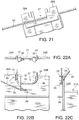
- the extending direction of the line material 40 is slanted in advance with respect to the first flange 22 as shown in Fig. 26 , and the line material 40 is guided to the notch 27.
- a path that the line material 40 can take to pass through the notch 27 is limited to a narrow range illustrated by arrows in Fig. 26 . It is difficult to efficiently guide the line material 40 to the notch 27. If the path that the line material 40 can take is narrow, it becomes also difficult to guide the line material 40 having a bending tendency.
- the line material 40 can be bent in the horizontal direction by using the first portion 28A as a fulcrum and can be guided to the winding barrel 21 over the second portion 28B.
- the line material 40 guided to the notch 27 floats from the winding barrel 21 by a portion corresponding to the step H.
- the line material 40 wound in a layered state on top of the portion also floats from the winding barrel 21. As a result, the height of the coil end becomes high.
- the guide surface 29 which guides the line material 40 is formed on the first portion 28A in a space between the first groove 31/winding start positioning projection 30 and the tab 26B.
- the line material guide is moved to a direction designated by an arrow in the figure and the line material 40 is brought into contact with the second portion 28B of the first flange 22 so as to position the winding start of the line material 40 on the winding barrel 21.
- the line material 40 is wound around the winding barrel 21.
- the winding of the line material 40 on the winding barrel 21 reaches the second flange 23.
- the line material 40 is newly wound on the layer of the line material 40 having been already wound.
- the winding of the line material 40 is performed in several layers between the first flange 22 and the second flange 23.
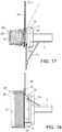
- the line material guide is moved to the outside of the first flange 22 in parallel with the winding barrel 21 as illustrated by an arrow in the figure. With this movement, the line material 40 having finished the winding on the winding barrel 21 is taken out to the outside of the first flange 22 through the notch 27.
- the coil-winding jig T is further driven to rotate by substantially 90 degrees and stopped.
- the line material 40 having passed the notch 27 is locked by the notch 35 of the winding end positioning projection 33.
- the line material 40 is cut off between the notch 35 and the line material guide.
- the winding start portion of the line material 40 is cut off between the winding start positioning projection 30 of the first portion 28A and the line-material retainer T1.
- the winding of the line material 40 on the winding barrel 21 is completed as shown in Fig. 8 .
- the single electromagnet 2 is constructed.
- the predetermined number of electromagnets 2 constructed as above are sequentially connected by inserting the projection 11A of the back yoke 11 to the recess 11B of the adjacent back yoke 11 to constitute the ring-shaped stator 1.
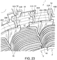
- the ring-shaped stator 1 is arranged inside the power collection and distribution bus ring 50 provided on the housing of an electric motor or a generator.
- the power collection and distribution bus ring 50 has a terminal 51 for connecting a start end 40A of the coil of each electromagnet 2 and a terminal 52 for connecting a terminal end 40B of the coil of each electromagnet 2 alternately provided.
- the terminal 51 has a gap 51A, and the gap 51A is closed by tightening the terminal 51 by a tool in a state where the start end 40A is inserted into the gap 51A. The start end 40A is thereby held in a fixed manner.
- the terminal 52 has a gap 52A, and the gap 52A is closed by tightening the terminal 52 by a tool in a state where the terminal end 40B is inserted into the gap 52A. The terminal end 40B is thereby held in a fixed manner.
- the coil start end 40A has a taking-out position fixed by going around the winding start positioning projection 30.
- the coil terminal end 40B has a taking-out position fixed by going around the winding end positioning projection 33.
- the coil start end 40A and the terminal end 40B are held inside the locking grooves 31 and 34, respectively.
- the locking grooves 31 and 34 have a role of preventing displacement of the coil start end 40A and the terminal end 40B and of holding them at positioning positions when the plurality of electromagnets 2 are assembled to the ring-shaped stator 1 and when the assembled stator 1 is arranged inside the power collection and distribution bus ring 50. Therefore, the first groove 31 and the second groove 34 further facilitate the connection work of the start end 40A and the terminal end 40B to the terminals 51 and 52.
- positioning itself of the line material 40 can be made by the winding start positioning projection 30 and the winding end positioning projection 33. Therefore, it is possible to form only the notch 27, the winding start positioning projection 30, and the winding end positioning projection 33 on the first flange 22 as illustrated and to omit the first groove 31 and the second groove 34.
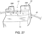
- This power collection and distribution bus ring 50 is provided with terminals 53 and 54 instead of the terminals 51 and 52 in Fig. 23 .
- the terminals 53 and 54 are supported by a support column 55 at positions overlapping with the locking grooves 31 and 34, respectively, with respect to the center axis direction of the stator 1.
- the terminal 53 has a gap 53A, and the gap 53A is closed by tightening the terminal 53 by a tool in a state where the start end 40A is inserted into the gap 53A, and the start end 40A is held in a fixed manner.
- the terminal 54 has a gap 54A, and the gap 54A is closed by tightening the terminal 54 by a tool in a state where the terminal end 40B is inserted into the gap 54A, and the start end 40B is held in a fixed manner.
- the terminals 53 and 54 are fixed to the support column 55 so that opening ends of the gaps 51A and 52A are directed to the center of the stator 1.
- the start end 40A and the terminal end 40B of the coil interfere with the terminals 53 and 54 when the ring-shaped stator 1 is inserted into the inside of the power collection and distribution bus ring 50.
- the first groove 31 and the second groove 34 in the first flange 22 and by inserting the ring-shaped stator 1 into the inside of the power collection and distribution bus ring 50 in a state where the coil start end 40A and the terminal end 40B are bent in the center direction of the stator 1 through the first groove 31 and the second groove 34, such interference can be prevented.
- the start end 40A and the terminal end 40B of the coil bent towards the center direction of the stator 1 through the first groove 31 and the second groove 34 are both straighten to a linear state so that they can be easily introduced into the gaps 53A and 54A.
- Tokugan2010-065753 The contents of Tokugan2010-065753 , with a filing date of March 23, 2010 in Japan, are referring to a further known related object.
- the line material 40 to be wound on the insulator 20 may have a square section or a circular section.
- the notch 27 is not limited to a rectangle but a U-shaped or V-shaped notch 27, for example, will do.
Landscapes
- Engineering & Computer Science (AREA)
- Power Engineering (AREA)
- Manufacturing & Machinery (AREA)
- Insulation, Fastening Of Motor, Generator Windings (AREA)
- Manufacture Of Motors, Generators (AREA)
Claims (7)
- Elektromagnet (2) für einen Stator, der umfasst:ein Statorpaket (10), das aus einem hinteren Joch (11) und einem Zahn (12) besteht, der von dem hinteren Joch (11) vorsteht;einen Isolator (20), der an dem Zahn (12) angebracht ist; undeine Spule, die um den Isolator (20) herum gewickelt istwobei:der Isolator (20) einen Wickelkörper (21), um den die Spule in einer Vielzahl von Schichten herum gewickelt ist, einen ersten Flansch (22), der an einem Ende des Wickelkörpers (21) an das hintere Joch (11) angrenzend ausgebildet ist, wobei der erste Flansch (22) eine Einkerbung (27) aufweist, durch die ein Leitungsmaterial (40) der Spule hindurchtritt, und einen zweiten Flansch (23) umfasst, der an einem anderen Ende des Wickelkörpers (21) so ausgebildet ist, dass das Leitungsmaterial (40) der Spule von einer Außenseite des ersten Flansches (22) durch die Einkerbung (27) hindurch zu dem Wickelkörper (21) geführt wird, um den Wickelkörper (21) herum gewickelt wird und durch die Einkerbung (27) hindurch an dem ersten Flansch (22) herausgeleitet wird; undder erste Flansch (22) einen ersten Abschnitt (28A), der sich an einer Seite der Einkerbung (27) befindet und zum Positionieren eines Wicklungs-Anfangs des Leitungsmaterials (40) dient, sowie einen zweiten Abschnitt (28B) umfasst, der sich an einer dem ersten Abschnitt (28A) gegenüberliegenden Seite der Einkerbung (27) befindet und zum Positionieren eines Wicklungs-Endes des Leitungsmaterials (40) dient,dadurch gekennzeichnet, dasseine Länge, um die der erste Abschnitt (28A) von dem Wickelkörper (21) vorsteht, so festgelegt ist, dass sie größer ist als eine Länge, um die der zweite Abschnitt (28B) von dem Wickelkörper (21) vorsteht.
- Elektromagnet (2) für einen Stator nach Anspruch 1, wobei der erste Abschnitt (28A) einen rechtwinkligen Eckenteil (30A) umfasst, der an der Einkerbung (27) anliegt, und der zweite Abschnitt (28B) einen runden Eckenteil (33A) umfasst, der an der Einkerbung (27) anliegt.
- Elektromagnet (2) für einen Stator nach Anspruch 1 oder Anspruch 2, wobei der zweite Abschnitt (28B) einen Vorsprung (33) zum Positionieren eines Wicklungs-Endes umfasst, der auf das hintere Joch (11) zu vorsteht und eine Wicklungs-Endposition des Leitungsmaterials (40) in der Nähe der Einkerbung (27) bestimmt.
- Elektromagnet (2) für einen Stator nach Anspruch 3, wobei der erste Abschnitt (28A) einen Vorsprung (30) zum Positionieren eines Wicklungs-Anfangs umfasst, der auf das hintere Joch (11) zu vorsteht und eine Wicklungs-Anfangsposition des Leitungsmaterials (40) in der Nähe der Einkerbung (27) bestimmt.
- Elektromagnet (2) für einen Stator nach Anspruch 4, wobei der erste Abschnitt eine erste Nut (31) umfasst, die an der der Einkerbung (27) gegenüberliegenden Seite des Vorsprungs (30) zum Positionieren eines Wicklungs-Anfangs ausgebildet ist und zum Positionieren eines Anfangs des Leitungsmaterials (40) dient, und der zweite Abschnitt (28B) eine zweite Nut (34) umfasst, die an einer der Einkerbung (27) gegenüberliegenden Seite des Vorsprungs (33) zum Positionieren eines Wicklungs-Endes ausgebildet ist und zum Positionieren eines Endes des Leitungsmaterials (40) dient.
- Elektromagnet (2) für einen Stator nach Anspruch 5, wobei eine Tiefe der ersten Nut (31) so festgelegt ist, dass sie größer ist als eine Tiefe der zweiten Nut (34).
- Verfahren zum Herstellen eines Elektromagneten (2) für einen Stator, das umfasst:Anbringen eines Isolators (20) an einem Zahn (12) eines Statorpakets (10), wobei der Isolator (12) einen Wickelkörper (21), einen ersten Flansch (22), der an einem Ende des Wickelkörpers (21) ausgebildet ist und eine Einkerbung (27) aufweist, durch die ein Leitungsmaterial (40) einer Spule hindurchtritt, sowie einen zweiten Flansch (23) umfasst, der an einem anderen Ende des Wickelkörpers (21) ausgebildet ist, und das Statorpaket (10) ein hinteres Joch (11) umfasst, von dem der Zahn (12) vorsteht, und Längen, um die der erste Flansch (22) von dem Wickelkörper (21) an beiden Seiten der Einkerbung (27) vorsteht, so festgelegt sind, dass sie sich voneinander unterscheiden;Führen des Leitungsmaterials (40) der Spule von einer Außenseite des ersten Flansches (22) durch die Einkerbung (27) hindurch zu dem Wickelkörper (21);Wickeln des Leitungsmaterials (40) auf den Wickelkörper (21) in einer Vielzahl von Schichten; undHerausführen des Leitungsmaterials (40) von dem Wickelkörper (21) durch die Einkerbung (27) hindurch zur Außenseite des ersten Flansches (22);wobei der erste Flansch (22) einen ersten Abschnitt (28A), der sich an einer Seite der Einkerbung (27) befindet und zum Positionieren eines Wicklungs-Anfangs des Leitungsmaterials (40) dient, sowie einen zweiten Abschnitt (28B) umfasst, der sich an einer dem ersten Abschnitt (28A) gegenüberliegenden Seite der Einkerbung (27) befindet und zum Positionieren eines Wicklungs-Endes des Leitungsmaterials (40) dient,dadurch gekennzeichnet, dasseine Länge, um die der erste Abschnitt (28A) von dem Wickelkörper (21) vorsteht, so festgelegt ist, dass sie größer ist als eine Länge, um die der zweite Abschnitt (28B) von dem Wickelkörper (21) vorsteht.
Applications Claiming Priority (2)
| Application Number | Priority Date | Filing Date | Title |
|---|---|---|---|
| JP2010065753A JP5636710B2 (ja) | 2010-03-23 | 2010-03-23 | 回転電機のインシュレータ及びステータ巻線構造の製造方法 |
| PCT/JP2011/054909 WO2011118357A1 (ja) | 2010-03-23 | 2011-03-03 | ステータ用電磁石及びステータ用電磁石の製造方法 |
Publications (3)
| Publication Number | Publication Date |
|---|---|
| EP2551993A1 EP2551993A1 (de) | 2013-01-30 |
| EP2551993A4 EP2551993A4 (de) | 2017-10-11 |
| EP2551993B1 true EP2551993B1 (de) | 2018-06-06 |
Family
ID=44672925
Family Applications (1)
| Application Number | Title | Priority Date | Filing Date |
|---|---|---|---|
| EP11759165.1A Active EP2551993B1 (de) | 2010-03-23 | 2011-03-03 | Elektromagnet für einen stator und herstellungsverfahren des elektromagnets für einen stator |
Country Status (5)
| Country | Link |
|---|---|
| US (1) | US9203274B2 (de) |
| EP (1) | EP2551993B1 (de) |
| JP (1) | JP5636710B2 (de) |
| CN (1) | CN102934331B (de) |
| WO (1) | WO2011118357A1 (de) |
Families Citing this family (32)
| Publication number | Priority date | Publication date | Assignee | Title |
|---|---|---|---|---|
| JP6033573B2 (ja) * | 2012-04-27 | 2016-11-30 | 株式会社ニフコ | ステーター用インシュレーター |
| FR2992493B1 (fr) * | 2012-06-20 | 2015-07-10 | Valeo Equip Electr Moteur | Isolant de bobine muni d'une ailette formant un mur electriquement isolant et element de machine electrique associe |
| KR20140003674A (ko) * | 2012-06-22 | 2014-01-10 | 엘지이노텍 주식회사 | 모터 |
| KR101940516B1 (ko) * | 2012-08-03 | 2019-04-11 | 삼성전자주식회사 | 모터와 이를 가지는 세탁기 |
| DE102012224012A1 (de) * | 2012-12-20 | 2014-06-26 | Tyco Electronics Belgium Ec Bvba | Spulenkörper zur Montage an einem Magnetkern, Reluktanzresolver und Verfahren zur Herstellung |
| CN103928999B (zh) * | 2013-01-10 | 2017-08-11 | 广东美的环境电器制造有限公司 | 定子、分块定子电机的绕线架及其绕线方法 |
| DE102013204759A1 (de) | 2013-03-19 | 2014-09-25 | Robert Bosch Gmbh | Zahnsegment zum Zusammenbau eines Stators oder Rotors einer elektrischen Maschine und Verfahren für die Herstellung einer solchen |
| JP5928904B2 (ja) | 2013-08-06 | 2016-06-01 | 株式会社安川電機 | インシュレータ、固定子結合体、回転電機、及び結線基板 |
| EP3065266B1 (de) * | 2013-10-30 | 2018-11-21 | Mitsubishi Electric Corporation | Elektromotor, verdichter damit und verfahren zur herstellung eines elektromotors |
| JP6225804B2 (ja) * | 2014-04-07 | 2017-11-08 | 株式会社安川電機 | ボビン及び回転電機 |
| JP6801946B2 (ja) * | 2015-01-20 | 2020-12-16 | トヨタ自動車株式会社 | インシュレータの形成方法 |
| US10038348B2 (en) * | 2015-08-12 | 2018-07-31 | Regal Beloit America, Inc. | Liner, stator assembly and associated method |
| CN105746757A (zh) * | 2016-03-25 | 2016-07-13 | 梧州市中茗茶业有限公司 | 茶叶发酵筒 |
| US11095171B2 (en) * | 2017-02-13 | 2021-08-17 | Lg Innotek Co., Ltd. | Stator and motor comprising same |
| JP6700211B2 (ja) * | 2017-03-15 | 2020-05-27 | アイチエレック株式会社 | 固定子および電動機 |
| JP6656474B2 (ja) * | 2017-06-02 | 2020-03-04 | デンソートリム株式会社 | 回転電機 |
| JP7314361B2 (ja) * | 2017-06-14 | 2023-07-25 | 株式会社マキタ | 電動工具 |
| WO2018230384A1 (ja) * | 2017-06-14 | 2018-12-20 | 株式会社 マキタ | 電動工具 |
| JP6994873B2 (ja) * | 2017-08-29 | 2022-01-14 | 株式会社ミツバ | ブラシレスモータ |
| EP3687043B1 (de) | 2017-09-20 | 2024-03-13 | Panasonic Intellectual Property Management Co., Ltd. | Isolator sowie stator und motor damit |
| EP3687041B1 (de) | 2017-09-20 | 2022-09-07 | Panasonic Intellectual Property Management Co., Ltd. | Isolator sowie stator und motor damit |
| CN111066226B (zh) | 2017-09-20 | 2022-04-29 | 松下知识产权经营株式会社 | 绝缘体、包括该绝缘体的定子以及包括该绝缘体的电动机 |
| CN107947420B (zh) * | 2017-11-28 | 2020-05-05 | 广东美的环境电器制造有限公司 | 用于电机的绝缘框、绝缘框架和电机定子及其制作方法 |
| CN111566907A (zh) * | 2018-01-24 | 2020-08-21 | 松下知识产权经营株式会社 | 绝缘体、包括该绝缘体的定子以及包括该绝缘体的电动机 |
| JP7004164B2 (ja) * | 2018-03-30 | 2022-01-21 | 株式会社豊田自動織機 | 回転電機のステータ、回転電機、及び回転電機のステータの製造方法 |
| GB2577546B (en) * | 2018-09-28 | 2023-05-24 | Dyson Technology Ltd | A stator core assembly |
| JP7247720B2 (ja) * | 2019-04-03 | 2023-03-29 | 株式会社プロテリアル | ラジアルギャップ型回転電機及びラジアルギャップ型回転電機の製造方法 |
| KR102317047B1 (ko) * | 2019-07-25 | 2021-10-25 | 엘지전자 주식회사 | 스테이터 및 이를 포함하는 모터 |
| JP2021083183A (ja) * | 2019-11-15 | 2021-05-27 | 日本電産株式会社 | ステータ、およびモータ |
| JP7632070B2 (ja) * | 2021-05-20 | 2025-02-19 | 株式会社デンソー | インシュレータ、ステータ及びステータの製造方法 |
| CN119448634A (zh) * | 2023-08-04 | 2025-02-14 | 爱知电机株式会社 | 电绝缘体组件、定子、电动机以及压缩机 |
| US20250239904A1 (en) * | 2024-01-18 | 2025-07-24 | Flowserve Pte. Ltd. | Coil assembly of an integrated motor pump or turbine having reduced thermal stress at cryogenic temperatures |
Family Cites Families (25)
| Publication number | Priority date | Publication date | Assignee | Title |
|---|---|---|---|---|
| JPH0510324Y2 (de) * | 1986-07-29 | 1993-03-15 | ||
| JP2002176753A (ja) * | 2000-12-07 | 2002-06-21 | Matsushita Electric Ind Co Ltd | 電動機固定子の製造方法及びその固定子 |
| JP2002284446A (ja) * | 2001-03-23 | 2002-10-03 | Moric Co Ltd | 電気機器の巻線ボビン |
| JP3718473B2 (ja) * | 2002-01-08 | 2005-11-24 | 草津電機株式会社 | 電動機 |
| DE20204507U1 (de) * | 2002-03-21 | 2002-06-06 | Grundfos A/S, Bjerringbro | Spulenträger als Isoliermaterial für eine elektrische Spule |
| JP3980402B2 (ja) * | 2002-05-13 | 2007-09-26 | 本田技研工業株式会社 | 回転電機 |
| DK1437817T3 (da) * | 2003-01-10 | 2013-06-17 | Askoll Holding Srl | Synkron elmotor med permanentmagnetrotor og forbedrede støttespoler til cirkulationspumper i varme- og airconditionanlæg |
| US7026739B2 (en) * | 2003-05-23 | 2006-04-11 | Honda Motor Co., Ltd | Stator and insulating bobbin and a manufacturing method of the stator |
| DE10345631A1 (de) * | 2003-09-29 | 2005-05-04 | Siemens Ag | Elektrische Maschine mit Trägervorrichtung mit Messsystem |
| JP4483480B2 (ja) * | 2004-08-27 | 2010-06-16 | アイシン精機株式会社 | 固定子及びモータ |
| US20060071569A1 (en) * | 2004-10-04 | 2006-04-06 | Stewart William P | Stator end caps and methods for positioning the lead and exit ends of the stator windings |
| US7095150B2 (en) * | 2004-10-21 | 2006-08-22 | Shop Vac Corporation | Apparatus for securing a bobbin of a reluctance machine |
| JP2007014147A (ja) * | 2005-06-30 | 2007-01-18 | Fujitsu General Ltd | 電動機 |
| JP4487914B2 (ja) | 2005-11-30 | 2010-06-23 | トヨタ自動車株式会社 | カセットコイルおよびカセットコイルを備える回転電機 |
| DE102006021903A1 (de) * | 2006-05-11 | 2007-11-22 | Zf Friedrichshafen Ag | Wickelkörper für eine Spule einer elektrischen Maschine |
| JP2008072801A (ja) * | 2006-09-13 | 2008-03-27 | Mitsuba Corp | コイル装置、ステータおよびモータ |
| JP2008148470A (ja) * | 2006-12-12 | 2008-06-26 | Hitachi Ltd | 集中巻コイルおよび集中巻きコイルの製造方法 |
| JP4697145B2 (ja) * | 2007-01-18 | 2011-06-08 | トヨタ自動車株式会社 | インシュレータボビン及びその組付方法 |
| JP4791387B2 (ja) * | 2007-02-21 | 2011-10-12 | 三菱電機株式会社 | 電機子 |
| JP5082524B2 (ja) * | 2007-03-19 | 2012-11-28 | 日産自動車株式会社 | 絶縁インシュレータ並びにステータの構造及び製造方法 |
| DE102007035531A1 (de) * | 2007-07-28 | 2009-01-29 | Zf Friedrichshafen Ag | Wicklungsanordnung für eine elektrische Maschine |
| JP4967909B2 (ja) * | 2007-08-02 | 2012-07-04 | 日産自動車株式会社 | 絶縁インシュレータ及びステータ並びにステータ製造方法 |
| JP5315743B2 (ja) * | 2008-03-26 | 2013-10-16 | アイシン精機株式会社 | 電動回転モーター |
| JP5153433B2 (ja) * | 2008-04-22 | 2013-02-27 | 三菱電機株式会社 | 電動機 |
| JP4868187B2 (ja) * | 2009-01-16 | 2012-02-01 | 株式会社富士通ゼネラル | 電動機 |
-
2010
- 2010-03-23 JP JP2010065753A patent/JP5636710B2/ja active Active
-
2011
- 2011-03-03 CN CN201180012738.4A patent/CN102934331B/zh active Active
- 2011-03-03 EP EP11759165.1A patent/EP2551993B1/de active Active
- 2011-03-03 WO PCT/JP2011/054909 patent/WO2011118357A1/ja not_active Ceased
- 2011-03-03 US US13/635,995 patent/US9203274B2/en active Active
Also Published As
| Publication number | Publication date |
|---|---|
| EP2551993A1 (de) | 2013-01-30 |
| US9203274B2 (en) | 2015-12-01 |
| EP2551993A4 (de) | 2017-10-11 |
| JP5636710B2 (ja) | 2014-12-10 |
| US20130009512A1 (en) | 2013-01-10 |
| CN102934331A (zh) | 2013-02-13 |
| CN102934331B (zh) | 2015-02-04 |
| JP2011200059A (ja) | 2011-10-06 |
| WO2011118357A1 (ja) | 2011-09-29 |
Similar Documents
| Publication | Publication Date | Title |
|---|---|---|
| EP2551993B1 (de) | Elektromagnet für einen stator und herstellungsverfahren des elektromagnets für einen stator | |
| EP3109981B1 (de) | Statoranordnungsverfahren und statoranordnungsvorrichtung | |
| US10727704B2 (en) | Magnetic pole, magnetic pole manufacturing method, and stator | |
| CN102801225B (zh) | 电动机芯、定子、以及定子的制造方法 | |
| US10892659B2 (en) | Stator unit, rotary electric machine including stator unit, and method of manufacturing stator unit | |
| EP3193428B1 (de) | Stator | |
| US10122226B2 (en) | Arrangement of coil wires in a rotor of an electric motor | |
| US20120262014A1 (en) | Bus bar device, stator, motor and manufacturing method for stator | |
| EP1793471A1 (de) | Anker, elektrische rotationsmaschine, gleichstrommotor und bürstenloser motor | |
| JP6358086B2 (ja) | ステータ組立装置及びステータ組立方法 | |
| US11404930B2 (en) | Insulator, and stator and motor comprising same | |
| US8256100B2 (en) | Stator manufacturing apparatus | |
| EP2738916B1 (de) | Stator eines Elektromotors mit einer Spulenisolierung | |
| CN103444057A (zh) | 铁心的绕线方法及定子 | |
| CN109586483B (zh) | 马达和定子 | |
| EP3687042B1 (de) | Isolator sowie stator und motor damit | |
| US20030011269A1 (en) | Armature for revolving -field electric machine | |
| US20050034541A1 (en) | Rotation angle sensor having single wire windings and method for winding a rotation angle sensor | |
| JP2007244115A (ja) | 電動機の巻線構造とその巻線方法及びその巻線装置 | |
| JP5450193B2 (ja) | 電機子の製造方法、モータの製造方法及び電機子の製造装置 | |
| EP1276207A2 (de) | Anker für rotierende elektrische Maschine | |
| CN119921493A (zh) | 用于三相电机的联接单元 | |
| CN118575394A (zh) | 旋转电机的定子、旋转电机、旋转电机的定子的制造方法以及旋转电机的制造方法 |
Legal Events
| Date | Code | Title | Description |
|---|---|---|---|
| PUAI | Public reference made under article 153(3) epc to a published international application that has entered the european phase |
Free format text: ORIGINAL CODE: 0009012 |
|
| 17P | Request for examination filed |
Effective date: 20121023 |
|
| AK | Designated contracting states |
Kind code of ref document: A1 Designated state(s): AL AT BE BG CH CY CZ DE DK EE ES FI FR GB GR HR HU IE IS IT LI LT LU LV MC MK MT NL NO PL PT RO RS SE SI SK SM TR |
|
| DAX | Request for extension of the european patent (deleted) | ||
| RA4 | Supplementary search report drawn up and despatched (corrected) |
Effective date: 20170912 |
|
| RIC1 | Information provided on ipc code assigned before grant |
Ipc: H02K 3/46 20060101AFI20170906BHEP Ipc: H02K 15/00 20060101ALI20170906BHEP Ipc: H02K 15/04 20060101ALI20170906BHEP Ipc: H02K 3/52 20060101ALI20170906BHEP |
|
| GRAP | Despatch of communication of intention to grant a patent |
Free format text: ORIGINAL CODE: EPIDOSNIGR1 |
|
| STAA | Information on the status of an ep patent application or granted ep patent |
Free format text: STATUS: GRANT OF PATENT IS INTENDED |
|
| RIC1 | Information provided on ipc code assigned before grant |
Ipc: H02K 3/46 20060101AFI20180206BHEP Ipc: H02K 3/52 20060101ALI20180206BHEP Ipc: H02K 15/04 20060101ALI20180206BHEP Ipc: H02K 15/00 20060101ALI20180206BHEP |
|
| INTG | Intention to grant announced |
Effective date: 20180221 |
|
| GRAS | Grant fee paid |
Free format text: ORIGINAL CODE: EPIDOSNIGR3 |
|
| GRAA | (expected) grant |
Free format text: ORIGINAL CODE: 0009210 |
|
| STAA | Information on the status of an ep patent application or granted ep patent |
Free format text: STATUS: THE PATENT HAS BEEN GRANTED |
|
| AK | Designated contracting states |
Kind code of ref document: B1 Designated state(s): AL AT BE BG CH CY CZ DE DK EE ES FI FR GB GR HR HU IE IS IT LI LT LU LV MC MK MT NL NO PL PT RO RS SE SI SK SM TR |
|
| REG | Reference to a national code |
Ref country code: GB Ref legal event code: FG4D |
|
| REG | Reference to a national code |
Ref country code: CH Ref legal event code: EP Ref country code: AT Ref legal event code: REF Ref document number: 1007122 Country of ref document: AT Kind code of ref document: T Effective date: 20180615 |
|
| REG | Reference to a national code |
Ref country code: IE Ref legal event code: FG4D |
|
| REG | Reference to a national code |
Ref country code: DE Ref legal event code: R096 Ref document number: 602011049053 Country of ref document: DE |
|
| REG | Reference to a national code |
Ref country code: NL Ref legal event code: MP Effective date: 20180606 |
|
| REG | Reference to a national code |
Ref country code: LT Ref legal event code: MG4D |
|
| PG25 | Lapsed in a contracting state [announced via postgrant information from national office to epo] |
Ref country code: BG Free format text: LAPSE BECAUSE OF FAILURE TO SUBMIT A TRANSLATION OF THE DESCRIPTION OR TO PAY THE FEE WITHIN THE PRESCRIBED TIME-LIMIT Effective date: 20180906 Ref country code: FI Free format text: LAPSE BECAUSE OF FAILURE TO SUBMIT A TRANSLATION OF THE DESCRIPTION OR TO PAY THE FEE WITHIN THE PRESCRIBED TIME-LIMIT Effective date: 20180606 Ref country code: NO Free format text: LAPSE BECAUSE OF FAILURE TO SUBMIT A TRANSLATION OF THE DESCRIPTION OR TO PAY THE FEE WITHIN THE PRESCRIBED TIME-LIMIT Effective date: 20180906 Ref country code: LT Free format text: LAPSE BECAUSE OF FAILURE TO SUBMIT A TRANSLATION OF THE DESCRIPTION OR TO PAY THE FEE WITHIN THE PRESCRIBED TIME-LIMIT Effective date: 20180606 Ref country code: ES Free format text: LAPSE BECAUSE OF FAILURE TO SUBMIT A TRANSLATION OF THE DESCRIPTION OR TO PAY THE FEE WITHIN THE PRESCRIBED TIME-LIMIT Effective date: 20180606 Ref country code: SE Free format text: LAPSE BECAUSE OF FAILURE TO SUBMIT A TRANSLATION OF THE DESCRIPTION OR TO PAY THE FEE WITHIN THE PRESCRIBED TIME-LIMIT Effective date: 20180606 Ref country code: CY Free format text: LAPSE BECAUSE OF FAILURE TO SUBMIT A TRANSLATION OF THE DESCRIPTION OR TO PAY THE FEE WITHIN THE PRESCRIBED TIME-LIMIT Effective date: 20180606 |
|
| PG25 | Lapsed in a contracting state [announced via postgrant information from national office to epo] |
Ref country code: LV Free format text: LAPSE BECAUSE OF FAILURE TO SUBMIT A TRANSLATION OF THE DESCRIPTION OR TO PAY THE FEE WITHIN THE PRESCRIBED TIME-LIMIT Effective date: 20180606 Ref country code: RS Free format text: LAPSE BECAUSE OF FAILURE TO SUBMIT A TRANSLATION OF THE DESCRIPTION OR TO PAY THE FEE WITHIN THE PRESCRIBED TIME-LIMIT Effective date: 20180606 Ref country code: GR Free format text: LAPSE BECAUSE OF FAILURE TO SUBMIT A TRANSLATION OF THE DESCRIPTION OR TO PAY THE FEE WITHIN THE PRESCRIBED TIME-LIMIT Effective date: 20180907 Ref country code: HR Free format text: LAPSE BECAUSE OF FAILURE TO SUBMIT A TRANSLATION OF THE DESCRIPTION OR TO PAY THE FEE WITHIN THE PRESCRIBED TIME-LIMIT Effective date: 20180606 |
|
| REG | Reference to a national code |
Ref country code: AT Ref legal event code: MK05 Ref document number: 1007122 Country of ref document: AT Kind code of ref document: T Effective date: 20180606 |
|
| PG25 | Lapsed in a contracting state [announced via postgrant information from national office to epo] |
Ref country code: NL Free format text: LAPSE BECAUSE OF FAILURE TO SUBMIT A TRANSLATION OF THE DESCRIPTION OR TO PAY THE FEE WITHIN THE PRESCRIBED TIME-LIMIT Effective date: 20180606 |
|
| PG25 | Lapsed in a contracting state [announced via postgrant information from national office to epo] |
Ref country code: EE Free format text: LAPSE BECAUSE OF FAILURE TO SUBMIT A TRANSLATION OF THE DESCRIPTION OR TO PAY THE FEE WITHIN THE PRESCRIBED TIME-LIMIT Effective date: 20180606 Ref country code: AT Free format text: LAPSE BECAUSE OF FAILURE TO SUBMIT A TRANSLATION OF THE DESCRIPTION OR TO PAY THE FEE WITHIN THE PRESCRIBED TIME-LIMIT Effective date: 20180606 Ref country code: PL Free format text: LAPSE BECAUSE OF FAILURE TO SUBMIT A TRANSLATION OF THE DESCRIPTION OR TO PAY THE FEE WITHIN THE PRESCRIBED TIME-LIMIT Effective date: 20180606 Ref country code: IS Free format text: LAPSE BECAUSE OF FAILURE TO SUBMIT A TRANSLATION OF THE DESCRIPTION OR TO PAY THE FEE WITHIN THE PRESCRIBED TIME-LIMIT Effective date: 20181006 Ref country code: SK Free format text: LAPSE BECAUSE OF FAILURE TO SUBMIT A TRANSLATION OF THE DESCRIPTION OR TO PAY THE FEE WITHIN THE PRESCRIBED TIME-LIMIT Effective date: 20180606 Ref country code: RO Free format text: LAPSE BECAUSE OF FAILURE TO SUBMIT A TRANSLATION OF THE DESCRIPTION OR TO PAY THE FEE WITHIN THE PRESCRIBED TIME-LIMIT Effective date: 20180606 Ref country code: CZ Free format text: LAPSE BECAUSE OF FAILURE TO SUBMIT A TRANSLATION OF THE DESCRIPTION OR TO PAY THE FEE WITHIN THE PRESCRIBED TIME-LIMIT Effective date: 20180606 |
|
| PG25 | Lapsed in a contracting state [announced via postgrant information from national office to epo] |
Ref country code: IT Free format text: LAPSE BECAUSE OF FAILURE TO SUBMIT A TRANSLATION OF THE DESCRIPTION OR TO PAY THE FEE WITHIN THE PRESCRIBED TIME-LIMIT Effective date: 20180606 Ref country code: SM Free format text: LAPSE BECAUSE OF FAILURE TO SUBMIT A TRANSLATION OF THE DESCRIPTION OR TO PAY THE FEE WITHIN THE PRESCRIBED TIME-LIMIT Effective date: 20180606 |
|
| REG | Reference to a national code |
Ref country code: DE Ref legal event code: R097 Ref document number: 602011049053 Country of ref document: DE |
|
| PLBE | No opposition filed within time limit |
Free format text: ORIGINAL CODE: 0009261 |
|
| STAA | Information on the status of an ep patent application or granted ep patent |
Free format text: STATUS: NO OPPOSITION FILED WITHIN TIME LIMIT |
|
| 26N | No opposition filed |
Effective date: 20190307 |
|
| PG25 | Lapsed in a contracting state [announced via postgrant information from national office to epo] |
Ref country code: DK Free format text: LAPSE BECAUSE OF FAILURE TO SUBMIT A TRANSLATION OF THE DESCRIPTION OR TO PAY THE FEE WITHIN THE PRESCRIBED TIME-LIMIT Effective date: 20180606 Ref country code: SI Free format text: LAPSE BECAUSE OF FAILURE TO SUBMIT A TRANSLATION OF THE DESCRIPTION OR TO PAY THE FEE WITHIN THE PRESCRIBED TIME-LIMIT Effective date: 20180606 |
|
| PG25 | Lapsed in a contracting state [announced via postgrant information from national office to epo] |
Ref country code: MC Free format text: LAPSE BECAUSE OF FAILURE TO SUBMIT A TRANSLATION OF THE DESCRIPTION OR TO PAY THE FEE WITHIN THE PRESCRIBED TIME-LIMIT Effective date: 20180606 |
|
| REG | Reference to a national code |
Ref country code: CH Ref legal event code: PL |
|
| PG25 | Lapsed in a contracting state [announced via postgrant information from national office to epo] |
Ref country code: AL Free format text: LAPSE BECAUSE OF FAILURE TO SUBMIT A TRANSLATION OF THE DESCRIPTION OR TO PAY THE FEE WITHIN THE PRESCRIBED TIME-LIMIT Effective date: 20180606 Ref country code: LU Free format text: LAPSE BECAUSE OF NON-PAYMENT OF DUE FEES Effective date: 20190303 |
|
| REG | Reference to a national code |
Ref country code: BE Ref legal event code: MM Effective date: 20190331 |
|
| PG25 | Lapsed in a contracting state [announced via postgrant information from national office to epo] |
Ref country code: CH Free format text: LAPSE BECAUSE OF NON-PAYMENT OF DUE FEES Effective date: 20190331 Ref country code: LI Free format text: LAPSE BECAUSE OF NON-PAYMENT OF DUE FEES Effective date: 20190331 Ref country code: IE Free format text: LAPSE BECAUSE OF NON-PAYMENT OF DUE FEES Effective date: 20190303 |
|
| PG25 | Lapsed in a contracting state [announced via postgrant information from national office to epo] |
Ref country code: BE Free format text: LAPSE BECAUSE OF NON-PAYMENT OF DUE FEES Effective date: 20190331 |
|
| PG25 | Lapsed in a contracting state [announced via postgrant information from national office to epo] |
Ref country code: TR Free format text: LAPSE BECAUSE OF FAILURE TO SUBMIT A TRANSLATION OF THE DESCRIPTION OR TO PAY THE FEE WITHIN THE PRESCRIBED TIME-LIMIT Effective date: 20180606 |
|
| PG25 | Lapsed in a contracting state [announced via postgrant information from national office to epo] |
Ref country code: MT Free format text: LAPSE BECAUSE OF NON-PAYMENT OF DUE FEES Effective date: 20190303 Ref country code: PT Free format text: LAPSE BECAUSE OF FAILURE TO SUBMIT A TRANSLATION OF THE DESCRIPTION OR TO PAY THE FEE WITHIN THE PRESCRIBED TIME-LIMIT Effective date: 20181008 |
|
| PG25 | Lapsed in a contracting state [announced via postgrant information from national office to epo] |
Ref country code: HU Free format text: LAPSE BECAUSE OF FAILURE TO SUBMIT A TRANSLATION OF THE DESCRIPTION OR TO PAY THE FEE WITHIN THE PRESCRIBED TIME-LIMIT; INVALID AB INITIO Effective date: 20110303 |
|
| PG25 | Lapsed in a contracting state [announced via postgrant information from national office to epo] |
Ref country code: MK Free format text: LAPSE BECAUSE OF FAILURE TO SUBMIT A TRANSLATION OF THE DESCRIPTION OR TO PAY THE FEE WITHIN THE PRESCRIBED TIME-LIMIT Effective date: 20180606 |
|
| PGFP | Annual fee paid to national office [announced via postgrant information from national office to epo] |
Ref country code: GB Payment date: 20260220 Year of fee payment: 16 |
|
| PGFP | Annual fee paid to national office [announced via postgrant information from national office to epo] |
Ref country code: DE Payment date: 20260219 Year of fee payment: 16 |
|
| PGFP | Annual fee paid to national office [announced via postgrant information from national office to epo] |
Ref country code: FR Payment date: 20260219 Year of fee payment: 16 |