EP2552784B1 - Appareil et procédé pour remplir des caisses avec des articles. - Google Patents
Appareil et procédé pour remplir des caisses avec des articles. Download PDFInfo
- Publication number
- EP2552784B1 EP2552784B1 EP11712432.1A EP11712432A EP2552784B1 EP 2552784 B1 EP2552784 B1 EP 2552784B1 EP 11712432 A EP11712432 A EP 11712432A EP 2552784 B1 EP2552784 B1 EP 2552784B1
- Authority
- EP
- European Patent Office
- Prior art keywords
- product
- conveyor
- divider
- moving
- conveying
- Prior art date
- Legal status (The legal status is an assumption and is not a legal conclusion. Google has not performed a legal analysis and makes no representation as to the accuracy of the status listed.)
- Active
Links
Images

Classifications
-
- B—PERFORMING OPERATIONS; TRANSPORTING
- B65—CONVEYING; PACKING; STORING; HANDLING THIN OR FILAMENTARY MATERIAL
- B65B—MACHINES, APPARATUS OR DEVICES FOR, OR METHODS OF, PACKAGING ARTICLES OR MATERIALS; UNPACKING
- B65B5/00—Packaging individual articles in containers or receptacles, e.g. bags, sacks, boxes, cartons, cans, jars
- B65B5/06—Packaging groups of articles, the groups being treated as single articles
- B65B5/061—Filled bags
-
- B—PERFORMING OPERATIONS; TRANSPORTING
- B65—CONVEYING; PACKING; STORING; HANDLING THIN OR FILAMENTARY MATERIAL
- B65B—MACHINES, APPARATUS OR DEVICES FOR, OR METHODS OF, PACKAGING ARTICLES OR MATERIALS; UNPACKING
- B65B35/00—Supplying, feeding, arranging or orientating articles to be packaged
- B65B35/10—Feeding, e.g. conveying, single articles
- B65B35/24—Feeding, e.g. conveying, single articles by endless belts or chains
-
- B—PERFORMING OPERATIONS; TRANSPORTING
- B65—CONVEYING; PACKING; STORING; HANDLING THIN OR FILAMENTARY MATERIAL
- B65B—MACHINES, APPARATUS OR DEVICES FOR, OR METHODS OF, PACKAGING ARTICLES OR MATERIALS; UNPACKING
- B65B35/00—Supplying, feeding, arranging or orientating articles to be packaged
- B65B35/30—Arranging and feeding articles in groups
-
- B—PERFORMING OPERATIONS; TRANSPORTING
- B65—CONVEYING; PACKING; STORING; HANDLING THIN OR FILAMENTARY MATERIAL
- B65B—MACHINES, APPARATUS OR DEVICES FOR, OR METHODS OF, PACKAGING ARTICLES OR MATERIALS; UNPACKING
- B65B35/00—Supplying, feeding, arranging or orientating articles to be packaged
- B65B35/30—Arranging and feeding articles in groups
- B65B35/50—Stacking one article, or group of articles, upon another before packaging
-
- B—PERFORMING OPERATIONS; TRANSPORTING
- B65—CONVEYING; PACKING; STORING; HANDLING THIN OR FILAMENTARY MATERIAL
- B65B—MACHINES, APPARATUS OR DEVICES FOR, OR METHODS OF, PACKAGING ARTICLES OR MATERIALS; UNPACKING
- B65B35/00—Supplying, feeding, arranging or orientating articles to be packaged
- B65B35/56—Orientating, i.e. changing the attitude of, articles, e.g. of non-uniform cross-section
-
- B—PERFORMING OPERATIONS; TRANSPORTING
- B65—CONVEYING; PACKING; STORING; HANDLING THIN OR FILAMENTARY MATERIAL
- B65B—MACHINES, APPARATUS OR DEVICES FOR, OR METHODS OF, PACKAGING ARTICLES OR MATERIALS; UNPACKING
- B65B5/00—Packaging individual articles in containers or receptacles, e.g. bags, sacks, boxes, cartons, cans, jars
- B65B5/08—Packaging groups of articles, the articles being individually gripped or guided for transfer to the containers or receptacles
-
- B—PERFORMING OPERATIONS; TRANSPORTING
- B65—CONVEYING; PACKING; STORING; HANDLING THIN OR FILAMENTARY MATERIAL
- B65B—MACHINES, APPARATUS OR DEVICES FOR, OR METHODS OF, PACKAGING ARTICLES OR MATERIALS; UNPACKING
- B65B5/00—Packaging individual articles in containers or receptacles, e.g. bags, sacks, boxes, cartons, cans, jars
- B65B5/10—Filling containers or receptacles progressively or in stages by introducing successive articles, or layers of articles
- B65B5/106—Filling containers or receptacles progressively or in stages by introducing successive articles, or layers of articles by pushers
-
- B—PERFORMING OPERATIONS; TRANSPORTING
- B65—CONVEYING; PACKING; STORING; HANDLING THIN OR FILAMENTARY MATERIAL
- B65G—TRANSPORT OR STORAGE DEVICES, e.g. CONVEYORS FOR LOADING OR TIPPING, SHOP CONVEYOR SYSTEMS OR PNEUMATIC TUBE CONVEYORS
- B65G47/00—Article or material-handling devices associated with conveyors; Methods employing such devices
- B65G47/22—Devices influencing the relative position or the attitude of articles during transit by conveyors
- B65G47/24—Devices influencing the relative position or the attitude of articles during transit by conveyors orientating the articles
- B65G47/244—Devices influencing the relative position or the attitude of articles during transit by conveyors orientating the articles by turning them about an axis substantially perpendicular to the conveying plane
-
- B—PERFORMING OPERATIONS; TRANSPORTING
- B65—CONVEYING; PACKING; STORING; HANDLING THIN OR FILAMENTARY MATERIAL
- B65G—TRANSPORT OR STORAGE DEVICES, e.g. CONVEYORS FOR LOADING OR TIPPING, SHOP CONVEYOR SYSTEMS OR PNEUMATIC TUBE CONVEYORS
- B65G57/00—Stacking of articles
- B65G57/02—Stacking of articles by adding to the top of the stack
- B65G57/03—Stacking of articles by adding to the top of the stack from above
- B65G57/035—Stacking of articles by adding to the top of the stack from above with a stepwise downward movement of the stack
Definitions
- a divider conveyor intermediate and independently driven from an input conveyor and a loading conveyor and which is movable in directions perpendicular to the conveying direction to rotate product while being conveyed and/or to align the product with a predetermined position in a collated row as claimed in claim 12.
- the product can be conveyed on the divider conveyor in the same orientation or in orientations perpendicular to the product orientation on the input conveyor and/or at different locations in the pack pattern to be cased.
- product can be conveyed onto a side wall at an acute angle to a loading table, with the side wall being moveable to a position generally perpendicular to the table to stand product on the table in the pack pattern to be cased.
- product is transferred from an upper containment plate onto a lower containment plate each moveable between containment positions and inoperative positions and onto a table of a lowerator.
- Product can be sandwiched between the upper containment plate and the table and between loading walls of the lowerator.
- Product can be pushed from the table in its lower position into a case after divider doors are opened.
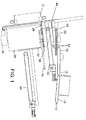
- apparatus 10 includes an input conveyor 12 supplying multiple product P by conveying in a conveying direction and in a random spacing but at a constant speed, with product P in the form shown of bags being conveyed with fin seals leading and trailing at its first and second ends and with first and second sides extending between the first and second ends.
- input conveyor 12 includes an endless conveyor belt 14 moving in the conveying direction.
- Apparatus 10 further includes a divider conveyor 16 conveying product P in the conveying direction.
- divider conveyor 16 includes an endless conveyor belt 18 moving in the conveying direction.
- the width of divider conveyor 16 and conveyor belt 18 is multiple times the width of input conveyor 12 and conveyor belt 14 in a direction perpendicular to the conveying direction.
- conveyor belt 18 is driven independently of conveyor belt 14 and at variable speeds.
- Product P is transferred from conveyor belt 14 onto conveyor belt 18.
- Divider conveyor 16 is moveable in a direction perpendicular to the conveying direction relative to conveyor 12.
- a suitable mechanism can be provided for mounting divider conveyor 16 for movement in the direction perpendicular to the conveying direction and for moving the divider conveyor 16 according to the desired operation.
- the location at which product is transferred to conveyor belt 18 from conveyor belt 14 will be dependent upon the location of divider conveyor 16 relative to input conveyor 12.
- Apparatus 10 further includes a loading conveyor 20 conveying product P in the conveying direction.
- loading conveyor 20 includes a plurality of rollers 24 supported upon an endless conveyor belt 22.
- the upper run of conveyor belt 22 moves opposite to the conveying direction so that rollers 24 rotate for moving product P in the conveying direction.
- the width of loading conveyor 20 perpendicular to the conveying direction is at least equal to the width of the case C into which product P is desired to be loaded. Further, loading conveyor 20 is driven independently of conveyors 12 and 14. Product P is conveyed from divider conveyor 16 onto loading conveyor 20.
- loading conveyor 20 can be of other forms including, but not limited to, an endless conveyor belt without rollers 24 or an air table in the form of a static plate with longitudinal grooves into which air is directed in a pulsed manner so that air streams along the concave sections of the grooves deliver product P while minimizing energy consumption.
- Apparatus 10 further includes a lowerator 26 including a table 28 having a width perpendicular to the conveying direction at least equal to the width of case C and a length in the conveying direction at least equal to the height of case C.
- Table 28 is moveable between an upper or home position and a lower position in a generally vertical direction and substantially perpendicular to the conveying direction.
- a suitable mechanism can be provided for moving table 28 according to the desired operation including, but not limited to, a servo motor 30.
- table 28 is at a small acute angle to the horizontal to utilize gravity when transferring product P therefrom.
- Lowerator 26 further includes a loader plate 32 moveable parallel to the table 28 in the lower position.
- a suitable mechanism can be provided for moving loader plate 32 including, but not limited to, being mounted to an endless drive mechanism 34 shown.
- Apparatus 10 further includes a lower containment plate 36 moveable generally in the conveying direction between a containment position and an inoperative position. In the containment position, containment plate 36 is generally parallel to and slightly spaced above table 28 in its upper position.
- a suitable mechanism 38 can be provided for moving containment plate 36 including, but not limited to, being mounted to a telescopic drive mechanism shown.
- Apparatus 10 further includes an upper containment plate 40 moveable generally in the conveying direction between a containment position and an inoperative position. In the containment position, containment plate 40 is generally parallel to and spaced above table 28 in its lower and upper positions and lower containment plate 36 in its containment position.
- a suitable mechanism can be provided for moving containment plate 40 including, but not limited to, being mounted to an endless drive mechanism 42 shown.
- the distance between loading conveyor 20 and a backwall 44 of the loading mechanism including lowerator 26 and plates 36 and 40 is at least equal to the height of the case C into which product P is desired to be loaded. It should be appreciated that the distance between loading conveyor 20 and backwall 44 can be adjustable such as by manually or through the use of a power source.
- the speed of conveying belt 18 can be adjusted to insure movement of conveyor 16 to the aligned position occurs before product P reaches conveyor 20. After conveyor 16 is at the aligned position, product P is transferred from conveyor 16 onto conveyor 20 and then transferred from conveyor 20 onto containment plate 40.
- containment plate 40 After a row of collated product P has been transferred from conveyor 20 onto upper containment plate 40, containment plate 40 is moved from its containment position to its inoperative position. In so moving, the row of collated product P supported upon containment plate 40 will fall onto and be transferred to and supported upon lower containment plate 36. The product transfer process is repeated with the next product P being transferred from conveyor 20 onto the previous collated row of product supported upon containment plate 36. Generally, the thickness of product determines the number of rows of product P that can be accumulated upon lower containment plate 36. After the desired number of rows of collated product P are supported upon containment plate 36, which will become a layer in case C, containment plate 40 is moved from its inoperative position to its containment position. Then, containment plate 36 is moved from its containment position to its inoperative position. In so moving, the rows of collated product supported upon containment plate 36 will fall onto and be transferred to and supported upon table 28.
- table 28 is moved up away from its lower position towards its upper position sufficiently to compress the length of the layer of product P between containment plate 40 and table 28. After compression, table 28 is moved to the lower position, allowing loading walls to compress the width of the layer of product P generally perpendicular to the conveying direction. In the lower position, the layer of product P will be positioned directly in front of loader plate 32 and behind divider doors extending over case C. After the divider doors are opened, loader plate 32 can be moved from its loading position to its unloading position to push the layer of product P into case C.
- loader plate 32 can be moved to its retracted position, the divider doors are closed, table 28 is moved to its upper position, and containment plate 36 is moved from its inoperative position to its containment position.
- product P will make a complete 90 degree turn relative to the conveying direction so that the first side is before the second side in the conveying direction.
- speed of conveyor belt 18 is increased, and conveyor 16 is moved perpendicular to the conveying direction until the path of product P is aligned with a predetermined position of a collated row. After alignment, product is conveyed from conveyor 16 onto conveyor 20 and then transferred to containment plate 40 or 36.
- Product P can be placed on table 28 with a combination of methods such as with one layer created by turning product P and another layer created by not turning product.
- Product P which is not turned is moved to a side wall 50 of lowerator 26 which is initially at an acute angle to the vertical and to the table 28.
- side wall 50 is raised towards a vertical position generally perpendicular to table 28, and product P will stand up. This operation produces a pack pattern which can be referred to as a side pack plus, as an example.
- product P can be transferred from conveyor 20 as an unfinished row which is allowed to scatter across the top as case C is rotated from its loading station. This operation produces a pack pattern which can be referred to as a loose pack, as an example.
- apparatus 10 as shown provides a conveying direction of product which is in line with case C, one of the reasons of a reduced overall size and a reduced footprint.
- Apparatus 10 according to the form shown requires fewer adjustments and fewer stored motions for different sized product.
- apparatus 10 includes fewer moving parts in the embodiment shown to reduce cost and improve reliability as well as result in increase productivity.
- the embodiments described herein are to be considered in all respects illustrative and not restrictive. The scope of the invention is to be indicated by the appended claims.
Landscapes
- Engineering & Computer Science (AREA)
- Mechanical Engineering (AREA)
- Specific Conveyance Elements (AREA)
- Intermediate Stations On Conveyors (AREA)
- Attitude Control For Articles On Conveyors (AREA)
Claims (15)
- Procédé consistant à :fournir de multiples produits (P) ayant chacun des première et seconde extrémités ainsi que des premier et second côtés s'étendant entre les première et seconde extrémités ;transférer un premier produit (P), avec la première extrémité qui se trouve avant la seconde extrémité dans une direction de transport et sur un convoyeur de séparation (16) ;transporter le premier produit (P) sur le convoyeur de séparation (16) dans la direction de transport ;transférer un second produit (P), avec la première extrémité qui se trouve avant la seconde extrémité dans la direction de transport sur le convoyeur de séparation (16) ;transporter le second produit (P) sur le convoyeur de séparation (16) ; etdéplacer le convoyeur de séparation (16) de façon perpendiculaire à la direction de transport pendant que le second produit (P) est transporté sur le convoyeur de séparation (16),caractérisé en ce que le déplacement du convoyeur de séparation (16) consiste à déplacer le convoyeur de séparation (16) pendant que le second produit (P) est transféré sur le convoyeur de séparation (16), avec le premier côté qui se trouve avant le second côté dans la direction de transport lorsque le second produit (P) est transporté sur le convoyeur de séparation (16).
- Procédé selon la revendication 1, dans lequel le déplacement du convoyeur de séparation (16) consiste à déplacer le convoyeur de séparation (16) après que le second produit (P) se trouve sur le convoyeur de séparation (16) avec la première extrémité qui se trouve avant la seconde extrémité dans la direction de transport.
- Procédé selon l'une quelconque des revendications précédentes, dans lequel le transfert du second produit (P) consiste à transporter le second produit (P) à une première vitesse de transport ; et dans lequel le transport du second produit (P) consiste à transporter le second produit (P) à une vitesse de transport inférieure à la première vitesse de transport pendant que le second produit (P) est transféré sur le convoyeur de séparation (16).
- Procédé selon l'une quelconque des revendications précédentes, dans lequel le transfert des premier et second produits (P) se fait à une vitesse égale et constante.
- Procédé consistant à :fournir de multiples produits (P) ayant chacun des première et seconde extrémités ainsi que des premier et second côtés s'étendant entre les première et seconde extrémités sur un convoyeur d'entrée ;transférer un premier produit (P), avec la première extrémité qui se trouve avant la seconde extrémité dans une direction de transport en provenance du convoyeur d'entrée et sur un convoyeur de séparation (16) ; ettransporter le premier produit (P) sur le convoyeur de séparation (16) dans la direction de transport ;caractérisé par le déplacement du convoyeur de séparation (16) de façon perpendiculaire à la direction de transport pendant que le premier produit (P) est transporté à la fois sur le convoyeur d'entrée et le convoyeur de séparation (16).
- Procédé selon la revendication 5, dans lequel le déplacement du convoyeur de séparation (16) consiste à déplacer le convoyeur de séparation (16) pendant que le premier produit (P) est transféré sur le convoyeur de séparation (16) avec le premier côté qui se trouve avant le second côté dans la direction de transport lorsque le premier produit (P) est transporté sur le convoyeur de séparation (16).
- Procédé selon la revendication 5 ou 6, dans lequel le transfert du premier produit (P) consiste à transporter le premier produit (P) à une première vitesse de transport ; et dans lequel le transport du premier produit (P) consiste à transporter le premier produit (P) à une vitesse de transport inférieure à la première vitesse de transport pendant que le premier produit (P) est transféré sur le convoyeur de séparation (16).
- Procédé selon l'une quelconque des revendications précédentes, consistant en outre à :transférer un produit (P) depuis le convoyeur de séparation (16) sur une table (28) ;déplacer la table (28) depuis une position de repos jusqu'à une position plus basse ;pousser un produit (P) depuis la table (28) pendant que la table (28) se trouve dans la position plus basse dans une boîte ; etrenvoyer la table (28) à la position de repos après avoir poussé le produit (P) et de préférencedans lequel le transfert d'un produit (P) depuis le convoyeur de séparation (16) consiste à :transférer un produit (P) depuis le convoyeur de séparation (16) sur une plaque de retenue supérieure (40) dans une position de retenue ;déplacer la plaque de retenue supérieure (40) depuis la position de retenue jusqu'à une position inopérante contraignant un produit (P) à tomber de la plaque de retenue supérieure (40) ; etrenvoyer la plaque de retenue supérieure (40) depuis la position inopérante jusqu'à la position de retenue après qu'un produit (P) tombe de la plaque de retenue supérieure (40) ; etdans lequel le déplacement de la table (28) consiste à déplacer la table (28) depuis la position de repos à l'écart de la position plus basse pour comprimer un produit (P) entre la plaque de retenue supérieure (40) et la table (28) après que la plaque de retenue supérieure (40) est renvoyée à la position de retenue et, ensuite, à déplacer la table (28) jusqu'à la position plus basse et de manière davantage préféréedans lequel le déplacement de la plaque de retenue supérieure (40) consiste à :contraindre un produit (P) à tomber de la plaque de retenue supérieure (40) sur une plaque de retenue inférieure (36) dans une position de retenue ;déplacer la plaque de retenue inférieure (36) depuis la position de retenue jusqu'à une position inopérante contraignant un produit (P) à tomber de la plaque de retenue inférieure (36) sur la table (28) ; etrenvoyer la plaque de retenue inférieure (36) depuis la position inopérante jusqu'à la position de retenue après qu'un produit (P) tombe de la plaque de retenue inférieure (36),dans lequel le déplacement de la plaque de retenue supérieure (40) consiste à actionner un mécanisme d'entraînement sans fin (34 ; 42) sur lequel la plaque de retenue supérieure (40) est montée ; et dans lequel le déplacement de la plaque de retenue inférieure (36) consiste à actionner un mécanisme d'entraînement télescopique sur lequel la plaque de retenue inférieure (36) est montée.
- Procédé selon la revendication 8, dans lequel le transfert d'un produit (P) depuis le convoyeur de séparation (16) consiste à :transférer un produit (P) depuis le convoyeur de séparation (16) sur un convoyeur de chargement (20) ; ettransférer un produit (P) depuis le convoyeur de chargement (20) sur une paroi latérale (50) selon un angle aigu par rapport à la table (28) ; etdéplacer la paroi latérale (50) depuis l'angle aigu jusqu'à ce qu'elle soit sensiblement perpendiculaire à la table (28) de sorte à poser un produit (P) sur la paroi latérale par rapport à la table (28).
- Procédé selon l'une quelconque des revendications précédentes consistant en outre à déplacer les parois de chargement pour comprimer un produit (P) après que la table (28) est déplacée jusqu'à la position plus basse et avant de pousser le produit (P).
- Procédé selon l'une quelconque des revendications précédentes, dans lequel la poussée du produit (P) consiste à ouvrir des portes de séparation après que la table (28) se déplace jusqu'à la position plus basse ; et à déplacer une plaque de dispositif de chargement (32) de façon parallèle à la table (28) dans la position plus basse, le déplacement de la plaque de dispositif de chargement (32) consistant à actionner un mécanisme d'entraînement sans fin (34 ; 42) sur lequel la plaque de dispositif de chargement (32) est montée.
- Appareil (10) pour charger un produit (P) comprenant, en combinaison : un convoyeur d'entrée (12) qui transporte un produit (P) ayant des première et seconde extrémités ainsi que des premier et second côtés dans une direction de transport, avec la première extrémité qui se trouve avant la seconde extrémité dans la direction de transport et avec les premier et second côtés qui sont transportés de façon parallèle à la direction de transport ; un convoyeur de séparation (16) qui reçoit un produit (P) en provenance du convoyeur d'entrée (12), avec le convoyeur de séparation (16) qui est entraîné indépendamment du convoyeur d'entrée (12) et avec le convoyeur de séparation (16) qui est mobile par rapport au convoyeur d'entrée (12), de façon sensiblement perpendiculaire à la direction de transport,
caractérisé en ce que le convoyeur de séparation (16) transporte le produit avec le premier côté avant le second côté dans la direction de transport. - Appareil (10) selon la revendication 12, dans lequel le convoyeur d'entrée (12) présente une largeur d'entrée perpendiculaire à la direction de transport ; et dans lequel le convoyeur de séparation (16) présente une largeur de séparation perpendiculaire à la direction de transport qui fait au moins deux fois la largeur d'entrée et dans lequel le convoyeur d'entrée (12) transporte un produit (P) à une vitesse constante ; et dans lequel le convoyeur de séparation (16) transporte un produit (P) à une vitesse variable indépendante de la vitesse constante.
- Appareil (10) selon l'une quelconque des revendications 12 à 13, comprenant en outre, en combinaison : une table (28) qui peut se déplacer entre une position de repos et une position plus basse ; et une plaque de dispositif de chargement (32) qui peut se déplacer de façon parallèle à la position de la table dans la position plus basse et entre une position de chargement et une position de déchargement et, de préférence,
comprenant en outre, en combinaison : une plaque de retenue supérieure (40) qui peut se déplacer entre une position de retenue et une position inopérante, avec la table (28) qui est mobile depuis la position de repos à l'écart de la position plus basse dans laquelle la plaque de retenue supérieure (40) se trouve en position de retenue et de manière davantage préférée
comprenant en outre, en combinaison : une plaque de retenue inférieure (36) qui peut se déplacer entre une position de retenue et une position inopérante, avec la plaque de retenue inférieure (36) qui se trouve entre la table (28) et la plaque de retenue supérieure (40), comprenant en outre en combinaison : un premier mécanisme d'entraînement sans fin (34), avec la plaque de dispositif de chargement (32) montée sur le premier mécanisme d'entraînement sans fin (34) ; un second mécanisme d'entraînement sans fin, avec la plaque de retenue supérieure (40) montée sur le second mécanisme d'entraînement sans fin (42) ; et un mécanisme d'entraînement télescopique, avec la plaque de retenue inférieure (36) montée sur le mécanisme d'entraînement télescopique. - Appareil (10) selon la revendication 14, comprenant en outre, en combinaison : un convoyeur de chargement (20), avec le convoyeur de chargement (20) qui reçoit un produit (P) en provenance du convoyeur de séparation (16) ; une paroi latérale (50) qui peut se déplacer entre un angle aigu par rapport à la table (28) et de façon sensiblement perpendiculaire à la table (28), avec la paroi latérale (50) qui reçoit un produit (P) du convoyeur de chargement (20) lorsqu'elle forme un angle aigu.
Applications Claiming Priority (2)
| Application Number | Priority Date | Filing Date | Title |
|---|---|---|---|
| US31829910P | 2010-03-27 | 2010-03-27 | |
| PCT/US2011/029894 WO2011126762A1 (fr) | 2010-03-27 | 2011-03-25 | Appareil et procédés permettant de charger un produit dans des boîtiers |
Publications (2)
| Publication Number | Publication Date |
|---|---|
| EP2552784A1 EP2552784A1 (fr) | 2013-02-06 |
| EP2552784B1 true EP2552784B1 (fr) | 2017-05-31 |
Family
ID=44201294
Family Applications (1)
| Application Number | Title | Priority Date | Filing Date |
|---|---|---|---|
| EP11712432.1A Active EP2552784B1 (fr) | 2010-03-27 | 2011-03-25 | Appareil et procédé pour remplir des caisses avec des articles. |
Country Status (8)
| Country | Link |
|---|---|
| US (1) | US9586706B2 (fr) |
| EP (1) | EP2552784B1 (fr) |
| CN (2) | CN102892675B (fr) |
| AU (1) | AU2011238756B2 (fr) |
| CA (1) | CA2813387C (fr) |
| MX (1) | MX346882B (fr) |
| RU (1) | RU2012145804A (fr) |
| WO (1) | WO2011126762A1 (fr) |
Families Citing this family (3)
| Publication number | Priority date | Publication date | Assignee | Title |
|---|---|---|---|---|
| US10759550B2 (en) * | 2015-09-25 | 2020-09-01 | Douglas Machine Inc. | Intermittent case packer assembly and methods |
| JP6967781B2 (ja) * | 2018-02-22 | 2021-11-17 | 株式会社イシダ | 箱詰め装置 |
| CN111422448A (zh) * | 2020-01-08 | 2020-07-17 | 鄂州市胜利软管股份有限公司 | 一种金属软管加工用包装辅助装置 |
Citations (2)
| Publication number | Priority date | Publication date | Assignee | Title |
|---|---|---|---|---|
| WO2003022716A1 (fr) * | 2001-09-05 | 2003-03-20 | Weber Maschinenbau Gmgh & Co. Kg | Dispositif de repartition |
| DE102007017035A1 (de) * | 2007-04-11 | 2008-10-16 | Alpma Alpenland Maschinenbau Gmbh | Vorrichtung zum Fördern von vereinzelten Gütern |
Family Cites Families (18)
| Publication number | Priority date | Publication date | Assignee | Title |
|---|---|---|---|---|
| US3512336A (en) * | 1967-08-28 | 1970-05-19 | John E Rosecrans | Apparatus for placing flexible packages in shipping containers |
| US3641735A (en) * | 1970-01-20 | 1972-02-15 | Jones & Co Inc R A | Bag packer with horizontal transfer |
| FR2248216A1 (en) | 1973-10-18 | 1975-05-16 | Pont A Mousson | Machine distributing articles from one line - transversely reciprocating conveyor feeds adjacent outlet lines |
| US3996723A (en) * | 1975-03-28 | 1976-12-14 | R. A. Jones & Company, Inc. | Article collator |
| DE2753720C2 (de) * | 1977-12-02 | 1984-10-18 | Lindemann Maschinenfabrik GmbH, 4000 Düsseldorf | Verfahren und Einrichtung zum Verladen von aus einer horizontalen Ballenpresse ausgestoßenen Ballen |
| ATE41399T1 (de) * | 1985-08-20 | 1989-04-15 | Rheon Automatic Machinery Co | Verfahren zum ordnen und befoerdern von produktreihen. |
| JPH01185455A (ja) * | 1988-01-20 | 1989-07-25 | Nec Home Electron Ltd | 機能検査システム |
| US5209339A (en) | 1988-04-28 | 1993-05-11 | Thurne Engineering Co., Ltd. | Conveyor system for multiplying slices of product |
| NL8900771A (nl) * | 1989-03-29 | 1990-10-16 | Bouwe Prakken | Inrichting voor het vullen van dozen met gevulde zakjes. |
| DE9115374U1 (de) * | 1991-12-11 | 1992-02-20 | Hauers, Manfred, 41751 Viersen | Abpackvorrichtung |
| NL1018612C2 (nl) * | 2001-07-23 | 2003-01-27 | Nutricia Nv | Werkwijze en inrichting voor het vullen van een houderbak met met een vloeistofachtige substantie gevulde zakken. |
| GB2390591B (en) * | 2002-07-13 | 2006-04-12 | Ckf Systems Ltd | Apparatus for forming a row |
| JP2005350147A (ja) * | 2004-06-08 | 2005-12-22 | Star Techno Kk | フリーフロー搬送システム |
| US7096650B2 (en) * | 2004-10-01 | 2006-08-29 | Blueprint Holding B.V. | Device for filling a carton |
| CN201089527Y (zh) * | 2007-07-09 | 2008-07-23 | 比亚迪股份有限公司 | 一种自动装盒装置 |
| CN101161551A (zh) * | 2007-11-27 | 2008-04-16 | 劲牌有限公司 | 瓶子自动顺序伺服理瓶方法及其装置 |
| CN201362382Y (zh) * | 2009-03-18 | 2009-12-16 | 安徽中烟工业公司合肥卷烟厂 | 一种装箱机的翻转装置 |
| DE102012211240A1 (de) | 2012-06-29 | 2014-04-17 | Weber Maschinenbau Gmbh Breidenbach | Vorrichtung zum Verteilen eines Stroms von Produkten |
-
2011
- 2011-03-25 CN CN201180023875.8A patent/CN102892675B/zh not_active Expired - Fee Related
- 2011-03-25 AU AU2011238756A patent/AU2011238756B2/en active Active
- 2011-03-25 RU RU2012145804/13A patent/RU2012145804A/ru not_active Application Discontinuation
- 2011-03-25 US US13/634,911 patent/US9586706B2/en active Active
- 2011-03-25 MX MX2012011163A patent/MX346882B/es active IP Right Grant
- 2011-03-25 EP EP11712432.1A patent/EP2552784B1/fr active Active
- 2011-03-25 CN CN201510885587.3A patent/CN105501487A/zh active Pending
- 2011-03-25 CA CA2813387A patent/CA2813387C/fr active Active
- 2011-03-25 WO PCT/US2011/029894 patent/WO2011126762A1/fr not_active Ceased
Patent Citations (2)
| Publication number | Priority date | Publication date | Assignee | Title |
|---|---|---|---|---|
| WO2003022716A1 (fr) * | 2001-09-05 | 2003-03-20 | Weber Maschinenbau Gmgh & Co. Kg | Dispositif de repartition |
| DE102007017035A1 (de) * | 2007-04-11 | 2008-10-16 | Alpma Alpenland Maschinenbau Gmbh | Vorrichtung zum Fördern von vereinzelten Gütern |
Also Published As
| Publication number | Publication date |
|---|---|
| MX346882B (es) | 2017-04-05 |
| US20130008762A1 (en) | 2013-01-10 |
| CN102892675A (zh) | 2013-01-23 |
| CA2813387C (fr) | 2018-04-24 |
| WO2011126762A1 (fr) | 2011-10-13 |
| CA2813387A1 (fr) | 2011-10-13 |
| AU2011238756B2 (en) | 2016-08-11 |
| MX2012011163A (es) | 2012-11-29 |
| EP2552784A1 (fr) | 2013-02-06 |
| CN102892675B (zh) | 2016-01-20 |
| RU2012145804A (ru) | 2014-05-10 |
| CN105501487A (zh) | 2016-04-20 |
| US9586706B2 (en) | 2017-03-07 |
| AU2011238756A1 (en) | 2012-10-18 |
Similar Documents
| Publication | Publication Date | Title |
|---|---|---|
| MXPA04009400A (es) | Dispositivo de transferencia retraible para un aparato de medicion. | |
| CN101516734A (zh) | 输送装置及包括该输送装置的装箱装置、装箱系统 | |
| CN104176456B (zh) | 伸缩输送机构和码垛机 | |
| CN102862809A (zh) | 备货系统及方法 | |
| CA2813387C (fr) | Appareil et procedes permettant de charger un produit dans des boitiers | |
| CN209366581U (zh) | 一种不同规格条烟集合包装设备 | |
| JP5793882B2 (ja) | 物品供給装置 | |
| JP6109509B2 (ja) | 物品整列供給装置 | |
| JPH08175662A (ja) | 搬送−仕分け−および貯蔵装置 | |
| CN108016887A (zh) | 一种关节式货物码放执行装置 | |
| JP2003002432A (ja) | 物品の整列搬送装置 | |
| US4237674A (en) | Apparatus for introducing stacks of paper sheets into boxes | |
| CN102336339B (zh) | 用于操作物品的方法和装置 | |
| US3531912A (en) | Assortment assembling apparatus | |
| US20120216490A1 (en) | Methods and apparatus for handling stackable articles | |
| JP2010126307A (ja) | 集積装置 | |
| CN207943584U (zh) | 一种货物自动码放装置 | |
| US20070264115A1 (en) | Method and Device to Form Stacks | |
| CN223421065U (zh) | 一种包装箱翻转机构 | |
| CN115535389B (zh) | 一种成型钢管的存放打包装置及其转运机构 | |
| CN101190741B (zh) | 物料调配储存与输出设备 | |
| JPH06298205A (ja) | 物品の箱詰め装置 | |
| CN217376334U (zh) | 一种输送线及装机设备 | |
| JP4182411B2 (ja) | 物品搬送装置 | |
| CN207030499U (zh) | 输送装置及使用该输送装置的装车机 |
Legal Events
| Date | Code | Title | Description |
|---|---|---|---|
| PUAI | Public reference made under article 153(3) epc to a published international application that has entered the european phase |
Free format text: ORIGINAL CODE: 0009012 |
|
| 17P | Request for examination filed |
Effective date: 20121029 |
|
| AK | Designated contracting states |
Kind code of ref document: A1 Designated state(s): AL AT BE BG CH CY CZ DE DK EE ES FI FR GB GR HR HU IE IS IT LI LT LU LV MC MK MT NL NO PL PT RO RS SE SI SK SM TR |
|
| DAX | Request for extension of the european patent (deleted) | ||
| 17Q | First examination report despatched |
Effective date: 20140414 |
|
| 17Q | First examination report despatched |
Effective date: 20140929 |
|
| 17Q | First examination report despatched |
Effective date: 20141002 |
|
| REG | Reference to a national code |
Ref country code: DE Ref legal event code: R079 Ref document number: 602011038318 Country of ref document: DE Free format text: PREVIOUS MAIN CLASS: B65B0005060000 Ipc: B65B0035500000 |
|
| RIC1 | Information provided on ipc code assigned before grant |
Ipc: B65B 5/06 20060101ALI20161110BHEP Ipc: B65B 35/24 20060101ALI20161110BHEP Ipc: B65G 57/03 20060101ALN20161110BHEP Ipc: B65G 47/244 20060101ALN20161110BHEP Ipc: B65B 5/10 20060101ALI20161110BHEP Ipc: B65B 35/56 20060101ALI20161110BHEP Ipc: B65B 5/08 20060101ALI20161110BHEP Ipc: B65B 35/50 20060101AFI20161110BHEP |
|
| GRAP | Despatch of communication of intention to grant a patent |
Free format text: ORIGINAL CODE: EPIDOSNIGR1 |
|
| RIC1 | Information provided on ipc code assigned before grant |
Ipc: B65G 57/03 20060101ALN20161208BHEP Ipc: B65B 35/56 20060101ALI20161208BHEP Ipc: B65B 35/24 20060101ALI20161208BHEP Ipc: B65B 5/08 20060101ALI20161208BHEP Ipc: B65B 5/06 20060101ALI20161208BHEP Ipc: B65G 47/244 20060101ALN20161208BHEP Ipc: B65B 35/50 20060101AFI20161208BHEP Ipc: B65B 5/10 20060101ALI20161208BHEP |
|
| INTG | Intention to grant announced |
Effective date: 20161219 |
|
| GRAS | Grant fee paid |
Free format text: ORIGINAL CODE: EPIDOSNIGR3 |
|
| GRAA | (expected) grant |
Free format text: ORIGINAL CODE: 0009210 |
|
| AK | Designated contracting states |
Kind code of ref document: B1 Designated state(s): AL AT BE BG CH CY CZ DE DK EE ES FI FR GB GR HR HU IE IS IT LI LT LU LV MC MK MT NL NO PL PT RO RS SE SI SK SM TR |
|
| REG | Reference to a national code |
Ref country code: CH Ref legal event code: EP Ref country code: GB Ref legal event code: FG4D |
|
| REG | Reference to a national code |
Ref country code: AT Ref legal event code: REF Ref document number: 897214 Country of ref document: AT Kind code of ref document: T Effective date: 20170615 |
|
| REG | Reference to a national code |
Ref country code: IE Ref legal event code: FG4D |
|
| REG | Reference to a national code |
Ref country code: DE Ref legal event code: R096 Ref document number: 602011038318 Country of ref document: DE |
|
| REG | Reference to a national code |
Ref country code: NL Ref legal event code: MP Effective date: 20170531 |
|
| REG | Reference to a national code |
Ref country code: LT Ref legal event code: MG4D |
|
| REG | Reference to a national code |
Ref country code: AT Ref legal event code: MK05 Ref document number: 897214 Country of ref document: AT Kind code of ref document: T Effective date: 20170531 |
|
| PG25 | Lapsed in a contracting state [announced via postgrant information from national office to epo] |
Ref country code: NO Free format text: LAPSE BECAUSE OF FAILURE TO SUBMIT A TRANSLATION OF THE DESCRIPTION OR TO PAY THE FEE WITHIN THE PRESCRIBED TIME-LIMIT Effective date: 20170831 Ref country code: AT Free format text: LAPSE BECAUSE OF FAILURE TO SUBMIT A TRANSLATION OF THE DESCRIPTION OR TO PAY THE FEE WITHIN THE PRESCRIBED TIME-LIMIT Effective date: 20170531 Ref country code: FI Free format text: LAPSE BECAUSE OF FAILURE TO SUBMIT A TRANSLATION OF THE DESCRIPTION OR TO PAY THE FEE WITHIN THE PRESCRIBED TIME-LIMIT Effective date: 20170531 Ref country code: GR Free format text: LAPSE BECAUSE OF FAILURE TO SUBMIT A TRANSLATION OF THE DESCRIPTION OR TO PAY THE FEE WITHIN THE PRESCRIBED TIME-LIMIT Effective date: 20170901 Ref country code: HR Free format text: LAPSE BECAUSE OF FAILURE TO SUBMIT A TRANSLATION OF THE DESCRIPTION OR TO PAY THE FEE WITHIN THE PRESCRIBED TIME-LIMIT Effective date: 20170531 Ref country code: LT Free format text: LAPSE BECAUSE OF FAILURE TO SUBMIT A TRANSLATION OF THE DESCRIPTION OR TO PAY THE FEE WITHIN THE PRESCRIBED TIME-LIMIT Effective date: 20170531 Ref country code: ES Free format text: LAPSE BECAUSE OF FAILURE TO SUBMIT A TRANSLATION OF THE DESCRIPTION OR TO PAY THE FEE WITHIN THE PRESCRIBED TIME-LIMIT Effective date: 20170531 |
|
| PG25 | Lapsed in a contracting state [announced via postgrant information from national office to epo] |
Ref country code: NL Free format text: LAPSE BECAUSE OF FAILURE TO SUBMIT A TRANSLATION OF THE DESCRIPTION OR TO PAY THE FEE WITHIN THE PRESCRIBED TIME-LIMIT Effective date: 20170531 Ref country code: RS Free format text: LAPSE BECAUSE OF FAILURE TO SUBMIT A TRANSLATION OF THE DESCRIPTION OR TO PAY THE FEE WITHIN THE PRESCRIBED TIME-LIMIT Effective date: 20170531 Ref country code: IS Free format text: LAPSE BECAUSE OF FAILURE TO SUBMIT A TRANSLATION OF THE DESCRIPTION OR TO PAY THE FEE WITHIN THE PRESCRIBED TIME-LIMIT Effective date: 20170930 Ref country code: LV Free format text: LAPSE BECAUSE OF FAILURE TO SUBMIT A TRANSLATION OF THE DESCRIPTION OR TO PAY THE FEE WITHIN THE PRESCRIBED TIME-LIMIT Effective date: 20170531 Ref country code: BG Free format text: LAPSE BECAUSE OF FAILURE TO SUBMIT A TRANSLATION OF THE DESCRIPTION OR TO PAY THE FEE WITHIN THE PRESCRIBED TIME-LIMIT Effective date: 20170831 Ref country code: SE Free format text: LAPSE BECAUSE OF FAILURE TO SUBMIT A TRANSLATION OF THE DESCRIPTION OR TO PAY THE FEE WITHIN THE PRESCRIBED TIME-LIMIT Effective date: 20170531 |
|
| PG25 | Lapsed in a contracting state [announced via postgrant information from national office to epo] |
Ref country code: DK Free format text: LAPSE BECAUSE OF FAILURE TO SUBMIT A TRANSLATION OF THE DESCRIPTION OR TO PAY THE FEE WITHIN THE PRESCRIBED TIME-LIMIT Effective date: 20170531 Ref country code: RO Free format text: LAPSE BECAUSE OF FAILURE TO SUBMIT A TRANSLATION OF THE DESCRIPTION OR TO PAY THE FEE WITHIN THE PRESCRIBED TIME-LIMIT Effective date: 20170531 Ref country code: EE Free format text: LAPSE BECAUSE OF FAILURE TO SUBMIT A TRANSLATION OF THE DESCRIPTION OR TO PAY THE FEE WITHIN THE PRESCRIBED TIME-LIMIT Effective date: 20170531 Ref country code: SK Free format text: LAPSE BECAUSE OF FAILURE TO SUBMIT A TRANSLATION OF THE DESCRIPTION OR TO PAY THE FEE WITHIN THE PRESCRIBED TIME-LIMIT Effective date: 20170531 Ref country code: CZ Free format text: LAPSE BECAUSE OF FAILURE TO SUBMIT A TRANSLATION OF THE DESCRIPTION OR TO PAY THE FEE WITHIN THE PRESCRIBED TIME-LIMIT Effective date: 20170531 |
|
| PG25 | Lapsed in a contracting state [announced via postgrant information from national office to epo] |
Ref country code: PL Free format text: LAPSE BECAUSE OF FAILURE TO SUBMIT A TRANSLATION OF THE DESCRIPTION OR TO PAY THE FEE WITHIN THE PRESCRIBED TIME-LIMIT Effective date: 20170531 Ref country code: SM Free format text: LAPSE BECAUSE OF FAILURE TO SUBMIT A TRANSLATION OF THE DESCRIPTION OR TO PAY THE FEE WITHIN THE PRESCRIBED TIME-LIMIT Effective date: 20170531 Ref country code: IT Free format text: LAPSE BECAUSE OF FAILURE TO SUBMIT A TRANSLATION OF THE DESCRIPTION OR TO PAY THE FEE WITHIN THE PRESCRIBED TIME-LIMIT Effective date: 20170531 |
|
| REG | Reference to a national code |
Ref country code: DE Ref legal event code: R097 Ref document number: 602011038318 Country of ref document: DE |
|
| PLBE | No opposition filed within time limit |
Free format text: ORIGINAL CODE: 0009261 |
|
| STAA | Information on the status of an ep patent application or granted ep patent |
Free format text: STATUS: NO OPPOSITION FILED WITHIN TIME LIMIT |
|
| 26N | No opposition filed |
Effective date: 20180301 |
|
| PG25 | Lapsed in a contracting state [announced via postgrant information from national office to epo] |
Ref country code: SI Free format text: LAPSE BECAUSE OF FAILURE TO SUBMIT A TRANSLATION OF THE DESCRIPTION OR TO PAY THE FEE WITHIN THE PRESCRIBED TIME-LIMIT Effective date: 20170531 |
|
| REG | Reference to a national code |
Ref country code: CH Ref legal event code: PL |
|
| PG25 | Lapsed in a contracting state [announced via postgrant information from national office to epo] |
Ref country code: MC Free format text: LAPSE BECAUSE OF FAILURE TO SUBMIT A TRANSLATION OF THE DESCRIPTION OR TO PAY THE FEE WITHIN THE PRESCRIBED TIME-LIMIT Effective date: 20170531 |
|
| REG | Reference to a national code |
Ref country code: BE Ref legal event code: MM Effective date: 20180331 |
|
| REG | Reference to a national code |
Ref country code: IE Ref legal event code: MM4A |
|
| PG25 | Lapsed in a contracting state [announced via postgrant information from national office to epo] |
Ref country code: LU Free format text: LAPSE BECAUSE OF NON-PAYMENT OF DUE FEES Effective date: 20180325 |
|
| PG25 | Lapsed in a contracting state [announced via postgrant information from national office to epo] |
Ref country code: IE Free format text: LAPSE BECAUSE OF NON-PAYMENT OF DUE FEES Effective date: 20180325 |
|
| PG25 | Lapsed in a contracting state [announced via postgrant information from national office to epo] |
Ref country code: LI Free format text: LAPSE BECAUSE OF NON-PAYMENT OF DUE FEES Effective date: 20180331 Ref country code: CH Free format text: LAPSE BECAUSE OF NON-PAYMENT OF DUE FEES Effective date: 20180331 Ref country code: BE Free format text: LAPSE BECAUSE OF NON-PAYMENT OF DUE FEES Effective date: 20180331 |
|
| PG25 | Lapsed in a contracting state [announced via postgrant information from national office to epo] |
Ref country code: FR Free format text: LAPSE BECAUSE OF NON-PAYMENT OF DUE FEES Effective date: 20180331 |
|
| PG25 | Lapsed in a contracting state [announced via postgrant information from national office to epo] |
Ref country code: MT Free format text: LAPSE BECAUSE OF NON-PAYMENT OF DUE FEES Effective date: 20180325 |
|
| PG25 | Lapsed in a contracting state [announced via postgrant information from national office to epo] |
Ref country code: TR Free format text: LAPSE BECAUSE OF FAILURE TO SUBMIT A TRANSLATION OF THE DESCRIPTION OR TO PAY THE FEE WITHIN THE PRESCRIBED TIME-LIMIT Effective date: 20170531 |
|
| PG25 | Lapsed in a contracting state [announced via postgrant information from national office to epo] |
Ref country code: PT Free format text: LAPSE BECAUSE OF FAILURE TO SUBMIT A TRANSLATION OF THE DESCRIPTION OR TO PAY THE FEE WITHIN THE PRESCRIBED TIME-LIMIT Effective date: 20170531 Ref country code: HU Free format text: LAPSE BECAUSE OF FAILURE TO SUBMIT A TRANSLATION OF THE DESCRIPTION OR TO PAY THE FEE WITHIN THE PRESCRIBED TIME-LIMIT; INVALID AB INITIO Effective date: 20110325 |
|
| PG25 | Lapsed in a contracting state [announced via postgrant information from national office to epo] |
Ref country code: CY Free format text: LAPSE BECAUSE OF FAILURE TO SUBMIT A TRANSLATION OF THE DESCRIPTION OR TO PAY THE FEE WITHIN THE PRESCRIBED TIME-LIMIT Effective date: 20170531 Ref country code: MK Free format text: LAPSE BECAUSE OF NON-PAYMENT OF DUE FEES Effective date: 20170531 |
|
| PG25 | Lapsed in a contracting state [announced via postgrant information from national office to epo] |
Ref country code: AL Free format text: LAPSE BECAUSE OF FAILURE TO SUBMIT A TRANSLATION OF THE DESCRIPTION OR TO PAY THE FEE WITHIN THE PRESCRIBED TIME-LIMIT Effective date: 20170531 |
|
| PGFP | Annual fee paid to national office [announced via postgrant information from national office to epo] |
Ref country code: GB Payment date: 20260324 Year of fee payment: 16 |
|
| PGFP | Annual fee paid to national office [announced via postgrant information from national office to epo] |
Ref country code: DE Payment date: 20260319 Year of fee payment: 16 |