EP2553763B1 - Réseau d'antenne active et procédé d'étalonnage du réseau d'antenne active - Google Patents
Réseau d'antenne active et procédé d'étalonnage du réseau d'antenne active Download PDFInfo
- Publication number
- EP2553763B1 EP2553763B1 EP11712820.7A EP11712820A EP2553763B1 EP 2553763 B1 EP2553763 B1 EP 2553763B1 EP 11712820 A EP11712820 A EP 11712820A EP 2553763 B1 EP2553763 B1 EP 2553763B1
- Authority
- EP
- European Patent Office
- Prior art keywords
- sounding signal
- signal
- antenna array
- active antenna
- receive paths
- Prior art date
- Legal status (The legal status is an assumption and is not a legal conclusion. Google has not performed a legal analysis and makes no representation as to the accuracy of the status listed.)
- Active
Links
Images


Classifications
-
- H—ELECTRICITY
- H01—ELECTRIC ELEMENTS
- H01Q—ANTENNAS, i.e. RADIO AERIALS
- H01Q3/00—Arrangements for changing or varying the orientation or the shape of the directional pattern of the waves radiated from an antenna or antenna system
- H01Q3/26—Arrangements for changing or varying the orientation or the shape of the directional pattern of the waves radiated from an antenna or antenna system varying the relative phase or relative amplitude of energisation between two or more active radiating elements; varying the distribution of energy across a radiating aperture
- H01Q3/267—Phased-array testing or checking devices
Definitions
- the field of the invention relates to an active antenna array and a method for calibration of the active antenna array.
- the use of mobile communications networks has increased over the last decade. Operators of the mobile communications networks have increased the number of base stations in order to meet an increased demand for service by users of the mobile communications networks. The operators of the mobile communications network wish to reduce the running costs of the base station.
- One option to do this is to implement a radio system as an antenna-embedded radio forming an active antenna array. Many of the components of the antenna-embedded radio may be implemented on one or more chips.
- Multiple receive paths in the antenna-embedded radio need to be synchronised in phase, delay and amplitude of signals travelling on the receive paths.
- Known techniques to establish variations in the phase, delay and amplitude of signals involve the injection of a known signal, termed the sounding signal, into one or more of the receive paths and, based on the comparison of the sounding signal and the received signal, the phase, delay and amplitude variations for the signals in the receive paths can be estimated. This allows for calibration of the receive paths by generation of correction coefficients to be applied to receive signals received along the multiple receive paths.
- the sounding signal can have either the same frequency in a carrier signal spectrum or beat a different frequency than the carrier signal spectrum.
- frequency of the sounding signal is in the carrier signal spectrum
- frequency and phase response of the analogue receive filters in the receive paths can be slightly different at the different frequencies. This implies that the measurement results for the phase, delay and amplitude of the signals measured at the frequency of the sounding signal may be slightly different than the measurement results for the phase, delay and amplitude of the signals measured at the frequency of the carrier signal.
- it is necessary to ensure that the frequency of the sounding signal is different than any of the frequencies of the other carrier signals which might be measured at the antenna embedded radio.
- blockers in the antenna embedded radio may block certain frequency bands and thus affect the quality of the error measurement.
- the sounding signal might be unintentionally transmitted from a receive antenna and then be detectable at a receive port of another (unconnected) receiver, which might violate regulations.
- a further known solution is to use a wide-band spectrum, for example a spread spectrum, sounding signal which is close to or below the noise floor of the carrier signals.
- a wide-band spectrum for example a spread spectrum, sounding signal which is close to or below the noise floor of the carrier signals.
- an extremely long sounding signal spreading code is necessary in order to have sufficient processing gain.
- Document EP 1 178 562 A1 relates to a method and a system for calibrating the reception and transmission of an antenna array for use in a cellular communication system.
- the calibration of the reception of the antenna array is performed by injecting a single calibration signal into each of a number of receiving antenna sections, in parallel.
- the signals are collected after having passed receiving components that might have distorted the phase and amplitude. Correction factors are generated and applied to received signals.
- the calibration of the transmission of the antenna array is performed in a similar way.
- a single calibration signal is generated and injected into each of a number of transmitting antenna sections, one at a time.
- the signals are collected, one at a time, after having passed transmitting components that might have distorted the phase and amplitude. Correction factors are generated and applied to signals that are to be transmitted.
- Document WO 95/34103 A1 relates to a method and apparatus for calibrating the transmission of an antenna array for use in a mobile radio communication system so as to increase the accuracy of the beam shape and direction of the antenna beam.
- the signal transmitted by each antenna section is then measured and correction factors can be formed for each antenna section.
- the antenna sections are then adjusted using the correction factors so as to ensure that each section is properly calibrated.
- the active antenna array of this disclosure comprises a plurality of receive paths, a control unit for generating a sounding signal, and a coupler for coupling the sounding signal into at least one of the plurality of receive paths.
- At least one switch is located in one of the plurality of receive paths for switching the one of the plurality of receive paths between one of a receiver and a calibration unit. This switch allows the sounding signal to be passed to each one of the receive paths to enable the receive paths to be separately calibrated.
- the active antenna array comprises a power meter for monitoring the average power of receive signals on at least one of the plurality of receive paths. This allows the power of the sounding signal to be kept at a level which does not interfere with the receive signals.
- the active antenna array may also include a power control for generating a power offset signal and adding the power offset signal to the sounding signal.
- the disclosure also teaches a method for calibration of an active antenna array which comprises generating an initial sounding signal, coupling the initial sounding signal into at least one of a plurality of receive paths to generate an adjusted sounding signal and comparing the adjusted sounding signal with the initial sounding signal, thus generating correlation coefficients.
- the correlation coefficients can be applied to the receive signals in a digital signal processor to correct of variations in phase, amplitude and delay along the various receive paths.
- the method may also comprise measuring power of receive signals over at least one of the plurality of receive paths and adding an offset power signal to the initial sounding signal.
- the comparing of the adjusted sounding signal with the initial sounding signal comprises storing of the initial values of the initial sounding signals and the storing of the adjusted values of the adjusted sounding signals and comparing the initial values with the adjusted values.
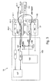
- Fig. 1 shows an example of an aspect of the invention - in this instance - for the calibration of a single receive path 30-1 in an active antenna array 10 by the generation of correction coefficients.
- the active antenna array 10 has a plurality of antenna elements 20 (only one of which 20-1 is shown in Fig. 1 ) which are connected to a plurality of transceivers 25.
- the transceivers 25 In the aspect shown in Fig. 1 only one of the transceivers 25 is shown and is labelled as 25-1. It will be appreciated that the teachings of this disclosure are relevant for an active antenna array 10 with any number of transceivers 25. Typically there will be eight or sixteen transceivers 25.
- the transceiver 25-1 has a receive path 30-1 and a transmission path 50-1. Both the receive path 30-1 and the transmission path 50-1 are connected to the antenna element 20 through a switch 40-1.
- the function of the switch 40-1 is to switch the antenna element 20 between transmit signals being transmitted on the transmission path 50-1 and receive signals being received from the antenna element 20 and passed to the receive path 30-1.
- the active antenna array 10 has a digital signal processor 100.
- the digital signal processor 100 is used to produce the transmit signals for transmission on the antenna elements 20 and to process the receive signals received from the antenna element 20.
- a beamforming block 107 in the digital signal processor 100 will use correction coefficients calculated as described later in this disclosure in order to account for phase, delay and amplitude variations on the receive signals received on the receive path 30-1. This function has been described in co-pending applications of Ubidyne and will be not discussed here in detail.
- the active antenna array 10 has further a control unit 105 whose function is to produce a sounding signal 110.
- the control unit 105 is connected to a first FIFO memory 120 and to a power controller 130.
- the power controller 130 is connected to an auxiliary transceiver 27.
- the sounding signal 110 is received from the power controller 130 and is converted by a digital-analogue-controller (DAC) 140 to an analogue signal and is passed along an auxiliary transmission path 145 to an output 146 and then to a multi-way switch 150.
- DAC digital-analogue-controller
- the auxiliary transceiver 27 also includes a receive path, but this is not used in this aspect of the invention.
- the multi-way switch 150 accepts the sounding signal 110 as an input and switches the sounding signal 110 to one of the plurality of the transceivers 25-1, 25-2,..., 25-N.
- the sounding signal 110 is passed through a coupler 155 to the switch 40-1 of the first one 25-1 of the transceivers 25.
- the multi-way switch 150 has a number of other outputs which are labelled in the Figure as being passed to other ones of the plurality of the transceivers 25-2,..., 25-N.
- the sounding signal 110 is passed to the receive path 30-1 and then to an analogue-digital-convertor 160-1.
- the sounding signal 110 (now in digital form) is passed further to the digital signal processor 100 for processing or to a second FIFO memory 180.
- a power meter 170 measures the power on the receive path 30-1 in the digital domain and passes the result of the power measurement to the control unit 105.
- the switch 190 is controlled by a signal from the control unit 105.
- Both the first FIFO memory 120 and the second FIFO memory 180 are connected to the control unit 105 processor 100 and the results can be compared with each other, as will be discussed below, in order to calibrate correction values for the signals received along the receive path 25-1.
- the first FIFO memory 120 and the second FIFO memory 180 together with the control unit 105 collectively form a calibration unit.
- Fig. 2 shows a method which is used for the measurement and thus calculation of the compensation values for the phase, delay and amplitude of the signals received along the receive path 25-1.
- the control unit 105 receives a trigger signal to indicate that a measurement needs to be started.
- step 205 the control unit 105 reads the power Prx of the receive signals on the receive path 30-1 by means of the power meter 170.
- the control unit 105 uses this power measurement Prx to configure the power control 130 in step 210 to send the sounding signal 110 with a power of Prx plus an offset power Pd.
- the offset power Pd is an offset amount which is used to optimise the power of the sounding signal 110 for the active antenna array 10 being used. It will be noted at this time that only the power control 130 has been configured. No sounding signal 110 is yet sent.
- a gate signal is sent from the control unit 105 which activates the calculation procedure.
- the power control 130 sends the sounding signal 110 with the specified power Prx + Pd through the auxiliary transceiver 27 and the multi-way switch 150 to the required one of the transceivers 25 which is to be calibrated.
- the aspect shown in Fig. 1 is of the transceiver 25-1.
- the multi-way switch 150 can switch the sounding signal 110 to any one of the other transceivers 25-2,...,25-B and will generally do this in a round-robin-manner so that in the course of time all of the transceivers 25-1, 25-2,...,25-N will be calibrated using the teachings of this disclosure.
- the switch 190 is open and thus the receive signals on the receive paths 30 are not passed through to the digital signal processor 100 but instead the values are collected by the second FIFO memory 180.
- the reason for the open switch 190 is to ensure that no distortions of the receive signals are passed through to the digital signal processor 100 during collections in the second FIFO memory 180.
- the first FIFO memory 120 will have obtained the values of the sounding signal 110 before the sounding signal 110 was passed through the auxiliary transceiver 27.
- step 220 the gate signal is deactivated and the switch 190 is closed to allow the receive signals to pass normally to the digital signal processor 100.
- the values in the first FIFO memory 120 and the second FIFO memory 180 are read out and compared with each other in step 220 in order to calculate the changes in the phase, delay and amplitude of the sounding signal passing through the receive path 30-1 of the transceiver 25. This corresponds to variations in the phase, delay and amplitude of the receive signals which pass along the receive path 30-1.
- This allows the correction coefficients to be calculated in step 225 which can be used to adjust the values of the phase, frequency and amplitude of the receive signals of the carrier signals received from the antenna element 20.
- Fig. 3 shows a further aspect of the invention in which the generation of the sounding signal 110 by the control unit 105 is replaced by the extraction of part of the receive signals received on the receive part in order to generate the sounding signal. This is done by passing the stored values in the second FIFO 180 through a second switch 195 to the auxiliary transceiver 27 as the sounding signal 110. The stored values from the second FIFO 180 are also passed to the first FIFO 120 so that the sounding signal 110 passed to the auxiliary transceiver can be compared with the sounding signal received after passage through the receive path 30-1.
- This aspect of the invention reduces the hardware required since there is no need to have a separate circuit to generate a separate sounding signal. Furthermore there is no need to adjust the power of the sounding signal 110 as the strength of the sounding signal 110 generated from the values in the second FIFO 180 are approximately the same as those of the receive signal.
- the control unit 105 is used to activate the calibration procedure. It does this by closing the second switch 195 so that values from the second FIFO 180 are passed to the auxiliary transceiver 27 and opening the first switch 190 so that none of the sounding signal 110 is passed through to the digital signal processor 100.
- the receive signal is captured in the second FIFO 180 and, after a short delay, passed through the transmission path of the auxiliary transceiver 27 to the multi-way switch 150.
- the values received in the second FIFO 180 are compared to the transmitted values stored in the first FIFO 110 to calculate the correction coefficients.
- the calculation of the correction coefficients should be carried out in a carrier-based manner because there could be differences in the power of the receive signals from two different ones of the carrier signals. Therefore the power meter 170 should be measuring the power of the required carrier signal, i.e. at the carrier signal. frequency. It will, of course, be noted that should more than one carrier's receive signals be received by the antenna element 20 it could be possible to include more than one power meter 170 in order to measure the power of the carrier signals of the different carriers at different frequencies. The inclusion of more than one power meter 170 enables the calculation of the correction coefficients to be carried out for more than one carrier signal at the same time. This minimises the impact of the time required for the calculation of the correction coefficients for the received carrier signals and also the impact of the calibration of the receive signals.
- a trigger placed within, for example the control unit 105, that triggers the calculation procedure only when there is a low probability of a significant change in the power of the received carrier signal.
- the sounding signal, its timing and its power can be selected such that any distortions due to the sounding signal in the receive signal are minimised.
- a certain time slot for the calculation procedure.
- a certain specified time and frequency slot should be used.
- a spreading code that is not in use and is not intended to be used could be used for the generation of the sounding signal and the calculation of correction coefficients for WCDMA signals.
- a certain time slot and spreading code could be used for the generation of the sounding signal and the calculation of correction coefficients for TD-SCDMA signals.
- the skilled person will understand that with other types of radio signals there are opportunities for selecting the correct timing and power of the sounding signal as well as its structure.
- Such software can enable, for example, the function, fabrication, modelling, simulation, description and/or testing of the apparatus and methods describe herein. For example, this can be accomplished through the use of general program languages (e.g., C, C++), hardware description languages (HDL) including Verilog HDL, VHDL, and so on, or other available programs.
- Such software can be disposed in any known computer useable medium such as semiconductor, magnetic disc, or optical disc (e.g., CD-ROM, DVD-ROM, etc.).
- the software can also be disposed as a computer data signal embodied in a computer useable (e.g. readable) transmission medium (e.g., carrier wave or any other medium including digital, optical, analogue-based medium).
- Embodiments of the present invention may include methods of providing the apparatus described herein by providing software describing the apparatus and subsequently transmitting the software as a computer data signal over a communication network including the internet and intranets.
- the apparatus and method described herein may be included in a semiconductor intellectual property core, such as a micro processor core (e.g., embodied in HDL) and transformed to hardware in the production of integrated circuits. Additionally, the apparatus and methods described herein may be embodied as a combination of hardware and software. Thus, the present invention should not be limited by any of the above-described exemplary embodiments, but should be defined only in accordance with the following claims and their equivalents.
Landscapes
- Variable-Direction Aerials And Aerial Arrays (AREA)
Claims (12)
- Ensemble d'antennes actives (10) pour un réseau de communication mobile, comprenant:- une pluralité de chemins de réception (30-1, ..., 30-N) ;- une unité de commande (105) pour engendrer un signal de sonde (110) ;- un coupleur pour coupler le signal de sonde (110) dans au moins l'un de la pluralité de chemins de réception (30-1, ..., 30-N) ;caractérisé en ce que l'ensemble d'antennes actives comprend :- au moins un commutateur (190) dans l'un de la pluralité de chemins de réception (30-1, ..., 30-N) pour commuter ledit un de la pluralité de chemins de réception (30-1, ..., 30-N) entre l'un d'un récepteur et d'une unité de calibration.
- Ensemble d'antennes actives (10) selon la revendication 1, comprenant en outre :un appareil de mesure de puissance (170) pour surveiller la puissance moyenne de signaux de réception sur au moins l'un de la pluralité de chemins de réception.
- Ensemble d'antennes actives (10) selon la revendication 2, comprenant en outre une commande de puissance pour engendrer un signal de décalage de puissance (Pd) et ajouter le signal de décalage de puissance (Pd) au signal de sonde (110).
- Ensemble d'antennes actives (10) selon l'une quelconque des revendications précédentes, comprenant en outre un commutateur à branches multiples (150) pour commuter le signal de sonde (110) entre des chemins différents de la pluralité de chemins de réception (30-1, ..., 30-N).
- Ensemble d'antennes actives (10) selon l'une quelconque des revendications précédentes, dans lequel l'unité de commande (105) engendre le signal de sonde depuis une portion d'un signal sur l'un de la pluralité de chemins de réception (30-1, ..., 30-N).
- Procédé de calibration d'un ensemble d'antennes actives (10) comprenant les étapes suivantes :- engendrer (210) un signal de sonde initial (110) ;- coupler le signal de sonde initial (110) dans au moins l'un d'une pluralité de chemins de réception de sorte d'engendrer un signal de sonde ajusté (110) ;- comparer (220) le signal de sonde ajusté (110') avec le signal de sonde initial ;- engendrer (225) des paramètres de calibration,
caractérisé en ce que le procédé comprend en outre l'étape de commutation de la sortie du au moins un de la pluralité de chemin de réception (30-1, ..., 30-N) entre un comparateur et un récepteur. - Procédé selon la revendication 6, comprenant en outre la commutation du signal de sonde initial entre des chemins différents de la pluralité de chemins de réception (30-1, ..., 30-N).
- Procédé selon l'une quelconque des revendications 6 ou 7, comprenant en outre les étapes de :- mesure de puissance de signaux de réception sur au moins l'un de la pluralité de chemins de réception (30-1, ..., 30-N) ; et- ajout d'un signal de décalage de puissance (Pd) au signal de sonde initial (110).
- Procédé selon l'une quelconque des revendications 6 à 8, dans lequel la comparaison du signal de sonde ajusté avec le signal de sonde initial comprend la mémorisation de valeurs initiales de signaux de sonde initiaux et la mémorisation des valeurs ajustées des signaux de sonde ajustés, et la comparaison des valeurs initiales avec les valeurs ajustées.
- Procédé selon l'une quelconque des revendications 6 à 9, dans lequel l'étape d'engendrer le signal de sonde est réalisée à partir de signaux sur l'un de la pluralité de chemins de réception.
- Produit programme d'ordinateur comprenant un support non transitoire utilisable par ordinateur ayant une logique de commande qui y est mémorisée pour amener un ordinateur à fabriquer l'ensemble d'antennes actives selon l'une quelconque des revendications 1 à 5.
- Produit programme d'ordinateur comprenant un support non transitoire utilisable par ordinateur ayant une logique de commande qui y est mémorisée pour amener un ordinateur à exécuter le procédé de calibration d'un ensemble d'antennes actives selon l'une des revendications 6 à 10.
Applications Claiming Priority (2)
| Application Number | Priority Date | Filing Date | Title |
|---|---|---|---|
| US12/751,342 US8340612B2 (en) | 2010-03-31 | 2010-03-31 | Active antenna array and method for calibration of the active antenna array |
| PCT/EP2011/054923 WO2011121033A1 (fr) | 2010-03-31 | 2011-03-30 | Réseau d'antenne active et procédé d'étalonnage du réseau d'antenne active |
Publications (2)
| Publication Number | Publication Date |
|---|---|
| EP2553763A1 EP2553763A1 (fr) | 2013-02-06 |
| EP2553763B1 true EP2553763B1 (fr) | 2015-12-02 |
Family
ID=44021763
Family Applications (1)
| Application Number | Title | Priority Date | Filing Date |
|---|---|---|---|
| EP11712820.7A Active EP2553763B1 (fr) | 2010-03-31 | 2011-03-30 | Réseau d'antenne active et procédé d'étalonnage du réseau d'antenne active |
Country Status (4)
| Country | Link |
|---|---|
| US (1) | US8340612B2 (fr) |
| EP (1) | EP2553763B1 (fr) |
| CN (1) | CN102870277B (fr) |
| WO (1) | WO2011121033A1 (fr) |
Families Citing this family (13)
| Publication number | Priority date | Publication date | Assignee | Title |
|---|---|---|---|---|
| EP2769483A4 (fr) * | 2011-10-21 | 2015-07-01 | Optis Cellular Technology Llc | Procédés, dispositif de traitement, programmes informatiques, produits programmes d'ordinateur et appareil formant antenne pour l'étalonnage d'un appareil formant antenne |
| CN102594426B (zh) * | 2012-02-21 | 2014-09-10 | 中兴通讯股份有限公司 | 一种有源天线多收发通道同步校准的装置和方法 |
| CN102624472B (zh) * | 2012-03-13 | 2016-08-31 | 南京中兴软件有限责任公司 | 一种实现有源天线多通道链路校准的方法及装置 |
| US9692393B2 (en) * | 2012-05-03 | 2017-06-27 | Telefonaktiebolaget Lm Ericsson (Publ) | Radio communication receiver apparatus and method |
| AU2013357018B2 (en) * | 2012-12-14 | 2017-04-20 | Bae Systems Plc | Antenna system calibration |
| CN103117786B (zh) * | 2013-01-18 | 2015-10-07 | 大唐移动通信设备有限公司 | 一种天线阵列校准方法和系统 |
| EP3427417B1 (fr) * | 2016-03-07 | 2022-05-11 | Satixfy UK Limited | Techniques d'étalonnage pour un réseau d'antennes |
| US10128894B1 (en) * | 2017-05-09 | 2018-11-13 | Analog Devices Global | Active antenna calibration |
| US11431423B2 (en) * | 2017-09-25 | 2022-08-30 | Telefonaktiebolaget Lm Ericsson (Publ) | Method and receiving terminal for real-time adaptive antenna calibration with training signal cancellation |
| CN109067475B (zh) * | 2018-08-04 | 2021-06-18 | 深圳市安芯无限科技有限公司 | 射频模块的频偏校准方法及系统 |
| US12074380B2 (en) * | 2019-06-27 | 2024-08-27 | Murata Manufacturing Co., Ltd | Phased array transceiver with built-in phase interferometer and/or transmitter linearization feedback |
| CN115486145B (zh) * | 2020-05-13 | 2025-07-29 | 瑞典爱立信有限公司 | 功率控制 |
| US12088013B2 (en) | 2021-03-30 | 2024-09-10 | Skyworks Solutions, Inc. | Frequency range two antenna array with switches for joining antennas for frequency range one communications |
Family Cites Families (32)
| Publication number | Priority date | Publication date | Assignee | Title |
|---|---|---|---|---|
| MX9605934A (es) | 1994-06-03 | 1997-12-31 | Ericsson Telefon Ab L M | Calibracion de una disposicion de antena. |
| KR100336233B1 (ko) | 1997-03-18 | 2002-06-20 | 모리시타 요이찌 | 어레이안테나무선수신장치의캘리브레이션장치및방법,지연검출장치,진폭검출장치및기지국장치 |
| US7035592B1 (en) | 1999-03-30 | 2006-04-25 | Sanyo Electric Co., Ltd. | Radio device and method of calibration of antenna directivity |
| JP4303373B2 (ja) | 1999-09-14 | 2009-07-29 | 株式会社日立コミュニケーションテクノロジー | 無線基地局装置 |
| DE19951525C2 (de) * | 1999-10-26 | 2002-01-24 | Siemens Ag | Verfahren zum Kalibrieren einer elektronisch phasengesteuerten Gruppenantenne in Funk-Kommunikationssystemen |
| EP1178562A1 (fr) | 2000-08-03 | 2002-02-06 | Telefonaktiebolaget L M Ericsson (Publ) | Etallonage d'un réseau d'antennes |
| JP4857467B2 (ja) | 2001-01-25 | 2012-01-18 | ソニー株式会社 | データ処理装置およびデータ処理方法、並びにプログラムおよび記録媒体 |
| KR100444822B1 (ko) * | 2001-08-07 | 2004-08-18 | 한국전자통신연구원 | 적응 배열 안테나 시스템의 오차 보정 장치 및 그 방법 |
| US6570527B1 (en) | 2001-09-28 | 2003-05-27 | Arraycomm, Inc. | Calibration of differential frequency-dependent characteristics of a radio communications system |
| JP2003143045A (ja) * | 2001-11-02 | 2003-05-16 | Fujitsu Ltd | 平均二乗誤差最小化アルゴリズムを用いて信号を処理する装置 |
| US20060019712A1 (en) | 2001-11-14 | 2006-01-26 | Seung-Won Choi | Calibration apparatus for smart antenna and method thereof |
| JP2003218621A (ja) | 2002-01-21 | 2003-07-31 | Nec Corp | アレーアンテナの校正装置及び校正方法 |
| KR100913883B1 (ko) * | 2002-04-19 | 2009-08-26 | 삼성전자주식회사 | 스마트 안테나의 출력 신호 왜곡 측정 및 보상 장치 및 방법 |
| JP4226442B2 (ja) * | 2002-11-14 | 2009-02-18 | パナソニック株式会社 | 無線通信装置 |
| CN1176555C (zh) * | 2002-12-25 | 2004-11-17 | 大唐移动通信设备有限公司 | 一种对智能天线阵系统进行实时校准的方法 |
| US7035601B2 (en) | 2003-02-27 | 2006-04-25 | Nokia Corporation | Data transmission method, base station and transmitter for compensating for non-linearities in a transmission chain |
| JP2004320367A (ja) | 2003-04-15 | 2004-11-11 | Matsushita Electric Ind Co Ltd | アレイアンテナ送受信装置 |
| KR100608553B1 (ko) | 2003-12-27 | 2006-08-03 | 한국전자통신연구원 | 실시간 오차 보정 기능을 가진 적응 배열 안테나시스템에서의 송수신 장치 및 그 방법 |
| US20050220310A1 (en) | 2004-03-30 | 2005-10-06 | Mcgrath William R | Technique and device for through-the-wall audio surveillance |
| JP4209355B2 (ja) * | 2004-03-30 | 2009-01-14 | 富士通株式会社 | 位相キャリブレーション方法及び位相キャリブレーション装置 |
| JP2006005525A (ja) | 2004-06-16 | 2006-01-05 | Nec Corp | 送信装置 |
| US7469137B2 (en) | 2004-12-17 | 2008-12-23 | Broadcom Corporation | Radio receiver DC offset cancellation via ADC input bias |
| JP4562542B2 (ja) | 2005-02-15 | 2010-10-13 | 三洋電機株式会社 | キャリブレーション方法ならびにそれを利用した基地局装置、端末装置および無線装置 |
| KR101052341B1 (ko) * | 2005-12-08 | 2011-07-27 | 한국전자통신연구원 | 다중 안테나를 갖는 스마트 안테나 시스템의 기지국 신호감시 장치 |
| JP5186748B2 (ja) | 2006-09-29 | 2013-04-24 | 富士通株式会社 | 無線通信装置および無線通信方法 |
| JP5170739B2 (ja) | 2007-11-05 | 2013-03-27 | 日本無線株式会社 | 補正手段付時分割2重送受信装置 |
| JP5051385B2 (ja) * | 2008-05-16 | 2012-10-17 | 日本電気株式会社 | アレーアンテナを用いた無線通信装置、その校正方法、及び無線通信基地局システム |
| US8073385B2 (en) | 2008-05-20 | 2011-12-06 | Powerwave Technologies, Inc. | Adaptive echo cancellation for an on-frequency RF repeater with digital sub-band filtering |
| US8102785B2 (en) * | 2008-05-21 | 2012-01-24 | Alcatel Lucent | Calibrating radiofrequency paths of a phased-array antenna |
| GB2461082A (en) * | 2008-06-20 | 2009-12-23 | Ubidyne Inc | Antenna array calibration with reduced interference from a payload signal |
| US8154452B2 (en) * | 2009-07-08 | 2012-04-10 | Raytheon Company | Method and apparatus for phased array antenna field recalibration |
| CN101923157B (zh) * | 2010-07-29 | 2013-05-01 | 西安空间无线电技术研究所 | 一种星载双通道角跟踪校准系统 |
-
2010
- 2010-03-31 US US12/751,342 patent/US8340612B2/en not_active Expired - Fee Related
-
2011
- 2011-03-30 WO PCT/EP2011/054923 patent/WO2011121033A1/fr not_active Ceased
- 2011-03-30 EP EP11712820.7A patent/EP2553763B1/fr active Active
- 2011-03-30 CN CN201180017991.9A patent/CN102870277B/zh active Active
Also Published As
| Publication number | Publication date |
|---|---|
| EP2553763A1 (fr) | 2013-02-06 |
| WO2011121033A1 (fr) | 2011-10-06 |
| CN102870277B (zh) | 2016-11-09 |
| HK1181925A1 (en) | 2013-11-15 |
| CN102870277A (zh) | 2013-01-09 |
| US20110244819A1 (en) | 2011-10-06 |
| US8340612B2 (en) | 2012-12-25 |
Similar Documents
| Publication | Publication Date | Title |
|---|---|---|
| US8340612B2 (en) | Active antenna array and method for calibration of the active antenna array | |
| JP7185084B2 (ja) | セルラーネットワークにおいて使用される通信デバイス、同通信デバイスに実装されるモジュール、及び同通信デバイスにおけるビーム制御の方法 | |
| EP2415186B1 (fr) | Système radio et procédé de retransmission de signaux radio à étalonnage de puissance de signaux radio de transmission | |
| EP2372930B1 (fr) | Réseau d'antennes actives et procédé pour son étalonnage | |
| US11158940B2 (en) | Self-calibration of antenna array system | |
| US20110085490A1 (en) | Absolute timing and tx power calibration of the tx path in a distibuted system | |
| EP2976840B1 (fr) | Procédé et agencement pour un étalonnage de phase de chemins d'émission et/ou réception d'un réseau d'antennes | |
| EP3767845B1 (fr) | Procédé d'essai et appareil émetteur | |
| US20100127932A1 (en) | Method of calibrating an active antenna and active antenna | |
| US10142006B1 (en) | Amplitude and phase calibration at a receiver chip in an antenna array | |
| US11101899B2 (en) | Method and node for enabling OTA testing of an EUT | |
| EP3348009B1 (fr) | Procédé et dispositif permettant d'essayer un noeud de communication | |
| US10447372B2 (en) | Amplitude and phase calibration at a transmitter chip in an antenna array | |
| US20160050569A1 (en) | Method for testing implicit beamforming performance of a multiple-input multiple-output radio frequency data packet signal transceiver | |
| KR20190088047A (ko) | 안테나 어레이로부터 방출된 무선 주파수 신호들의 예측되는 위상 시프트들의 확인을 가능하게 하는 방법 | |
| KR102409687B1 (ko) | Rf 체인의 특성을 측정하기 위한 방법 및 장치 | |
| US20150111507A1 (en) | Millimeter wave conductive setup | |
| US20140210683A1 (en) | Calibrating a retro-directive array for an asymmetric wireless link | |
| US20130260699A1 (en) | Generating test measurement values for automatic calibration using an internal testing load | |
| Gaydos et al. | Experimental demonstration of a software-defined-radio adaptive beamformer | |
| WO2007112546A1 (fr) | Système de mesure de champ proche sans absorbeur à plusieurs canaux | |
| KR102409690B1 (ko) | Rf 체인의 특성을 측정하기 위한 방법 및 장치 | |
| HK1181925B (en) | Active antenna array and method for calibration of the active antenna array | |
| Saleem et al. | Leveraging frequency agility of an MIMO antenna cluster with a transmitter IC | |
| Liu et al. | 0cal: Zero-Cost Calibration for mmWave Networks |
Legal Events
| Date | Code | Title | Description |
|---|---|---|---|
| PUAI | Public reference made under article 153(3) epc to a published international application that has entered the european phase |
Free format text: ORIGINAL CODE: 0009012 |
|
| 17P | Request for examination filed |
Effective date: 20121031 |
|
| AK | Designated contracting states |
Kind code of ref document: A1 Designated state(s): AL AT BE BG CH CY CZ DE DK EE ES FI FR GB GR HR HU IE IS IT LI LT LU LV MC MK MT NL NO PL PT RO RS SE SI SK SM TR |
|
| DAX | Request for extension of the european patent (deleted) | ||
| REG | Reference to a national code |
Ref country code: HK Ref legal event code: DE Ref document number: 1181925 Country of ref document: HK |
|
| RAP1 | Party data changed (applicant data changed or rights of an application transferred) |
Owner name: KATHREIN-WERKE KG |
|
| GRAP | Despatch of communication of intention to grant a patent |
Free format text: ORIGINAL CODE: EPIDOSNIGR1 |
|
| INTG | Intention to grant announced |
Effective date: 20150708 |
|
| GRAS | Grant fee paid |
Free format text: ORIGINAL CODE: EPIDOSNIGR3 |
|
| GRAA | (expected) grant |
Free format text: ORIGINAL CODE: 0009210 |
|
| AK | Designated contracting states |
Kind code of ref document: B1 Designated state(s): AL AT BE BG CH CY CZ DE DK EE ES FI FR GB GR HR HU IE IS IT LI LT LU LV MC MK MT NL NO PL PT RO RS SE SI SK SM TR |
|
| REG | Reference to a national code |
Ref country code: GB Ref legal event code: FG4D |
|
| REG | Reference to a national code |
Ref country code: AT Ref legal event code: REF Ref document number: 763987 Country of ref document: AT Kind code of ref document: T Effective date: 20151215 Ref country code: CH Ref legal event code: EP |
|
| REG | Reference to a national code |
Ref country code: IE Ref legal event code: FG4D |
|
| REG | Reference to a national code |
Ref country code: DE Ref legal event code: R096 Ref document number: 602011021801 Country of ref document: DE |
|
| REG | Reference to a national code |
Ref country code: SE Ref legal event code: TRGR Ref country code: FR Ref legal event code: PLFP Year of fee payment: 6 |
|
| REG | Reference to a national code |
Ref country code: NL Ref legal event code: MP Effective date: 20160302 |
|
| REG | Reference to a national code |
Ref country code: LT Ref legal event code: MG4D |
|
| REG | Reference to a national code |
Ref country code: AT Ref legal event code: MK05 Ref document number: 763987 Country of ref document: AT Kind code of ref document: T Effective date: 20151202 |
|
| PG25 | Lapsed in a contracting state [announced via postgrant information from national office to epo] |
Ref country code: ES Free format text: LAPSE BECAUSE OF FAILURE TO SUBMIT A TRANSLATION OF THE DESCRIPTION OR TO PAY THE FEE WITHIN THE PRESCRIBED TIME-LIMIT Effective date: 20151202 Ref country code: LT Free format text: LAPSE BECAUSE OF FAILURE TO SUBMIT A TRANSLATION OF THE DESCRIPTION OR TO PAY THE FEE WITHIN THE PRESCRIBED TIME-LIMIT Effective date: 20151202 Ref country code: NO Free format text: LAPSE BECAUSE OF FAILURE TO SUBMIT A TRANSLATION OF THE DESCRIPTION OR TO PAY THE FEE WITHIN THE PRESCRIBED TIME-LIMIT Effective date: 20160302 |
|
| REG | Reference to a national code |
Ref country code: HK Ref legal event code: GR Ref document number: 1181925 Country of ref document: HK |
|
| PG25 | Lapsed in a contracting state [announced via postgrant information from national office to epo] |
Ref country code: PL Free format text: LAPSE BECAUSE OF FAILURE TO SUBMIT A TRANSLATION OF THE DESCRIPTION OR TO PAY THE FEE WITHIN THE PRESCRIBED TIME-LIMIT Effective date: 20151202 Ref country code: LV Free format text: LAPSE BECAUSE OF FAILURE TO SUBMIT A TRANSLATION OF THE DESCRIPTION OR TO PAY THE FEE WITHIN THE PRESCRIBED TIME-LIMIT Effective date: 20151202 Ref country code: NL Free format text: LAPSE BECAUSE OF FAILURE TO SUBMIT A TRANSLATION OF THE DESCRIPTION OR TO PAY THE FEE WITHIN THE PRESCRIBED TIME-LIMIT Effective date: 20151202 Ref country code: GR Free format text: LAPSE BECAUSE OF FAILURE TO SUBMIT A TRANSLATION OF THE DESCRIPTION OR TO PAY THE FEE WITHIN THE PRESCRIBED TIME-LIMIT Effective date: 20160303 Ref country code: RS Free format text: LAPSE BECAUSE OF FAILURE TO SUBMIT A TRANSLATION OF THE DESCRIPTION OR TO PAY THE FEE WITHIN THE PRESCRIBED TIME-LIMIT Effective date: 20151202 Ref country code: AT Free format text: LAPSE BECAUSE OF FAILURE TO SUBMIT A TRANSLATION OF THE DESCRIPTION OR TO PAY THE FEE WITHIN THE PRESCRIBED TIME-LIMIT Effective date: 20151202 |
|
| PG25 | Lapsed in a contracting state [announced via postgrant information from national office to epo] |
Ref country code: IS Free format text: LAPSE BECAUSE OF FAILURE TO SUBMIT A TRANSLATION OF THE DESCRIPTION OR TO PAY THE FEE WITHIN THE PRESCRIBED TIME-LIMIT Effective date: 20151202 |
|
| PG25 | Lapsed in a contracting state [announced via postgrant information from national office to epo] |
Ref country code: IT Free format text: LAPSE BECAUSE OF FAILURE TO SUBMIT A TRANSLATION OF THE DESCRIPTION OR TO PAY THE FEE WITHIN THE PRESCRIBED TIME-LIMIT Effective date: 20151202 Ref country code: CZ Free format text: LAPSE BECAUSE OF FAILURE TO SUBMIT A TRANSLATION OF THE DESCRIPTION OR TO PAY THE FEE WITHIN THE PRESCRIBED TIME-LIMIT Effective date: 20151202 |
|
| PG25 | Lapsed in a contracting state [announced via postgrant information from national office to epo] |
Ref country code: SK Free format text: LAPSE BECAUSE OF FAILURE TO SUBMIT A TRANSLATION OF THE DESCRIPTION OR TO PAY THE FEE WITHIN THE PRESCRIBED TIME-LIMIT Effective date: 20151202 Ref country code: IS Free format text: LAPSE BECAUSE OF FAILURE TO SUBMIT A TRANSLATION OF THE DESCRIPTION OR TO PAY THE FEE WITHIN THE PRESCRIBED TIME-LIMIT Effective date: 20160402 Ref country code: SM Free format text: LAPSE BECAUSE OF FAILURE TO SUBMIT A TRANSLATION OF THE DESCRIPTION OR TO PAY THE FEE WITHIN THE PRESCRIBED TIME-LIMIT Effective date: 20151202 Ref country code: BE Free format text: LAPSE BECAUSE OF NON-PAYMENT OF DUE FEES Effective date: 20160331 Ref country code: EE Free format text: LAPSE BECAUSE OF FAILURE TO SUBMIT A TRANSLATION OF THE DESCRIPTION OR TO PAY THE FEE WITHIN THE PRESCRIBED TIME-LIMIT Effective date: 20151202 Ref country code: PT Free format text: LAPSE BECAUSE OF FAILURE TO SUBMIT A TRANSLATION OF THE DESCRIPTION OR TO PAY THE FEE WITHIN THE PRESCRIBED TIME-LIMIT Effective date: 20160404 Ref country code: RO Free format text: LAPSE BECAUSE OF FAILURE TO SUBMIT A TRANSLATION OF THE DESCRIPTION OR TO PAY THE FEE WITHIN THE PRESCRIBED TIME-LIMIT Effective date: 20151202 |
|
| REG | Reference to a national code |
Ref country code: DE Ref legal event code: R097 Ref document number: 602011021801 Country of ref document: DE |
|
| PLBE | No opposition filed within time limit |
Free format text: ORIGINAL CODE: 0009261 |
|
| STAA | Information on the status of an ep patent application or granted ep patent |
Free format text: STATUS: NO OPPOSITION FILED WITHIN TIME LIMIT |
|
| PG25 | Lapsed in a contracting state [announced via postgrant information from national office to epo] |
Ref country code: MC Free format text: LAPSE BECAUSE OF FAILURE TO SUBMIT A TRANSLATION OF THE DESCRIPTION OR TO PAY THE FEE WITHIN THE PRESCRIBED TIME-LIMIT Effective date: 20151202 Ref country code: DK Free format text: LAPSE BECAUSE OF FAILURE TO SUBMIT A TRANSLATION OF THE DESCRIPTION OR TO PAY THE FEE WITHIN THE PRESCRIBED TIME-LIMIT Effective date: 20151202 Ref country code: LU Free format text: LAPSE BECAUSE OF FAILURE TO SUBMIT A TRANSLATION OF THE DESCRIPTION OR TO PAY THE FEE WITHIN THE PRESCRIBED TIME-LIMIT Effective date: 20160330 |
|
| REG | Reference to a national code |
Ref country code: CH Ref legal event code: PL |
|
| 26N | No opposition filed |
Effective date: 20160905 |
|
| PG25 | Lapsed in a contracting state [announced via postgrant information from national office to epo] |
Ref country code: SI Free format text: LAPSE BECAUSE OF FAILURE TO SUBMIT A TRANSLATION OF THE DESCRIPTION OR TO PAY THE FEE WITHIN THE PRESCRIBED TIME-LIMIT Effective date: 20151202 |
|
| REG | Reference to a national code |
Ref country code: IE Ref legal event code: MM4A |
|
| PG25 | Lapsed in a contracting state [announced via postgrant information from national office to epo] |
Ref country code: BE Free format text: LAPSE BECAUSE OF FAILURE TO SUBMIT A TRANSLATION OF THE DESCRIPTION OR TO PAY THE FEE WITHIN THE PRESCRIBED TIME-LIMIT Effective date: 20151202 |
|
| PG25 | Lapsed in a contracting state [announced via postgrant information from national office to epo] |
Ref country code: IE Free format text: LAPSE BECAUSE OF NON-PAYMENT OF DUE FEES Effective date: 20160330 Ref country code: CH Free format text: LAPSE BECAUSE OF NON-PAYMENT OF DUE FEES Effective date: 20160331 Ref country code: LI Free format text: LAPSE BECAUSE OF NON-PAYMENT OF DUE FEES Effective date: 20160331 |
|
| REG | Reference to a national code |
Ref country code: FR Ref legal event code: PLFP Year of fee payment: 7 |
|
| PG25 | Lapsed in a contracting state [announced via postgrant information from national office to epo] |
Ref country code: MT Free format text: LAPSE BECAUSE OF FAILURE TO SUBMIT A TRANSLATION OF THE DESCRIPTION OR TO PAY THE FEE WITHIN THE PRESCRIBED TIME-LIMIT Effective date: 20151202 |
|
| REG | Reference to a national code |
Ref country code: FR Ref legal event code: PLFP Year of fee payment: 8 |
|
| PG25 | Lapsed in a contracting state [announced via postgrant information from national office to epo] |
Ref country code: CY Free format text: LAPSE BECAUSE OF FAILURE TO SUBMIT A TRANSLATION OF THE DESCRIPTION OR TO PAY THE FEE WITHIN THE PRESCRIBED TIME-LIMIT Effective date: 20151202 Ref country code: HU Free format text: LAPSE BECAUSE OF FAILURE TO SUBMIT A TRANSLATION OF THE DESCRIPTION OR TO PAY THE FEE WITHIN THE PRESCRIBED TIME-LIMIT; INVALID AB INITIO Effective date: 20110330 |
|
| PG25 | Lapsed in a contracting state [announced via postgrant information from national office to epo] |
Ref country code: MK Free format text: LAPSE BECAUSE OF FAILURE TO SUBMIT A TRANSLATION OF THE DESCRIPTION OR TO PAY THE FEE WITHIN THE PRESCRIBED TIME-LIMIT Effective date: 20151202 Ref country code: HR Free format text: LAPSE BECAUSE OF FAILURE TO SUBMIT A TRANSLATION OF THE DESCRIPTION OR TO PAY THE FEE WITHIN THE PRESCRIBED TIME-LIMIT Effective date: 20151202 Ref country code: TR Free format text: LAPSE BECAUSE OF FAILURE TO SUBMIT A TRANSLATION OF THE DESCRIPTION OR TO PAY THE FEE WITHIN THE PRESCRIBED TIME-LIMIT Effective date: 20151202 Ref country code: MT Free format text: LAPSE BECAUSE OF FAILURE TO SUBMIT A TRANSLATION OF THE DESCRIPTION OR TO PAY THE FEE WITHIN THE PRESCRIBED TIME-LIMIT Effective date: 20160331 |
|
| PG25 | Lapsed in a contracting state [announced via postgrant information from national office to epo] |
Ref country code: BG Free format text: LAPSE BECAUSE OF FAILURE TO SUBMIT A TRANSLATION OF THE DESCRIPTION OR TO PAY THE FEE WITHIN THE PRESCRIBED TIME-LIMIT Effective date: 20151202 |
|
| REG | Reference to a national code |
Ref country code: DE Ref legal event code: R081 Ref document number: 602011021801 Country of ref document: DE Owner name: TELEFONAKTIEBOLAGET LM ERICSSON (PUBL), SE Free format text: FORMER OWNER: KATHREIN-WERKE KG, 83022 ROSENHEIM, DE Ref country code: DE Ref legal event code: R082 Ref document number: 602011021801 Country of ref document: DE Representative=s name: 24IP LAW GROUP SONNENBERG FORTMANN, DE Ref country code: DE Ref legal event code: R081 Ref document number: 602011021801 Country of ref document: DE Owner name: KATHREIN SE, DE Free format text: FORMER OWNER: KATHREIN-WERKE KG, 83022 ROSENHEIM, DE |
|
| PG25 | Lapsed in a contracting state [announced via postgrant information from national office to epo] |
Ref country code: AL Free format text: LAPSE BECAUSE OF FAILURE TO SUBMIT A TRANSLATION OF THE DESCRIPTION OR TO PAY THE FEE WITHIN THE PRESCRIBED TIME-LIMIT Effective date: 20151202 |
|
| REG | Reference to a national code |
Ref country code: GB Ref legal event code: 732E Free format text: REGISTERED BETWEEN 20190314 AND 20190320 |
|
| PGFP | Annual fee paid to national office [announced via postgrant information from national office to epo] |
Ref country code: FR Payment date: 20190531 Year of fee payment: 10 |
|
| REG | Reference to a national code |
Ref country code: DE Ref legal event code: R081 Ref document number: 602011021801 Country of ref document: DE Owner name: TELEFONAKTIEBOLAGET LM ERICSSON (PUBL), SE Free format text: FORMER OWNER: KATHREIN SE, 83022 ROSENHEIM, DE Ref country code: DE Ref legal event code: R082 Ref document number: 602011021801 Country of ref document: DE Representative=s name: 24IP LAW GROUP SONNENBERG FORTMANN, DE |
|
| PGFP | Annual fee paid to national office [announced via postgrant information from national office to epo] |
Ref country code: SE Payment date: 20200327 Year of fee payment: 10 Ref country code: FI Payment date: 20200327 Year of fee payment: 10 |
|
| REG | Reference to a national code |
Ref country code: GB Ref legal event code: 732E Free format text: REGISTERED BETWEEN 20210311 AND 20210317 |
|
| REG | Reference to a national code |
Ref country code: GB Ref legal event code: 732E Free format text: REGISTERED BETWEEN 20210318 AND 20210324 |
|
| REG | Reference to a national code |
Ref country code: FI Ref legal event code: PCE Owner name: TELEFONAKTIEBOLAGET LM ERICSSON (PUBL) |
|
| REG | Reference to a national code |
Ref country code: FI Ref legal event code: MAE |
|
| PG25 | Lapsed in a contracting state [announced via postgrant information from national office to epo] |
Ref country code: FI Free format text: LAPSE BECAUSE OF NON-PAYMENT OF DUE FEES Effective date: 20210330 |
|
| PG25 | Lapsed in a contracting state [announced via postgrant information from national office to epo] |
Ref country code: SE Free format text: LAPSE BECAUSE OF NON-PAYMENT OF DUE FEES Effective date: 20210331 Ref country code: FR Free format text: LAPSE BECAUSE OF NON-PAYMENT OF DUE FEES Effective date: 20210331 |
|
| PGFP | Annual fee paid to national office [announced via postgrant information from national office to epo] |
Ref country code: DE Payment date: 20230329 Year of fee payment: 13 |
|
| REG | Reference to a national code |
Ref country code: DE Ref legal event code: R119 Ref document number: 602011021801 Country of ref document: DE |
|
| PG25 | Lapsed in a contracting state [announced via postgrant information from national office to epo] |
Ref country code: DE Free format text: LAPSE BECAUSE OF NON-PAYMENT OF DUE FEES Effective date: 20241001 |
|
| PG25 | Lapsed in a contracting state [announced via postgrant information from national office to epo] |
Ref country code: DE Free format text: LAPSE BECAUSE OF NON-PAYMENT OF DUE FEES Effective date: 20241001 |
|
| PGFP | Annual fee paid to national office [announced via postgrant information from national office to epo] |
Ref country code: GB Payment date: 20260327 Year of fee payment: 16 |