EP2554205B1 - Dispositif médical pourvu d'un revêtement coulissant, et seringue - Google Patents
Dispositif médical pourvu d'un revêtement coulissant, et seringue Download PDFInfo
- Publication number
- EP2554205B1 EP2554205B1 EP11762798.4A EP11762798A EP2554205B1 EP 2554205 B1 EP2554205 B1 EP 2554205B1 EP 11762798 A EP11762798 A EP 11762798A EP 2554205 B1 EP2554205 B1 EP 2554205B1
- Authority
- EP
- European Patent Office
- Prior art keywords
- coating layer
- component
- syringe
- medical appliance
- gasket
- Prior art date
- Legal status (The legal status is an assumption and is not a legal conclusion. Google has not performed a legal analysis and makes no representation as to the accuracy of the status listed.)
- Active
Links
Images


Classifications
-
- F—MECHANICAL ENGINEERING; LIGHTING; HEATING; WEAPONS; BLASTING
- F16—ENGINEERING ELEMENTS AND UNITS; GENERAL MEASURES FOR PRODUCING AND MAINTAINING EFFECTIVE FUNCTIONING OF MACHINES OR INSTALLATIONS; THERMAL INSULATION IN GENERAL
- F16J—PISTONS; CYLINDERS; SEALINGS
- F16J15/00—Sealings
- F16J15/16—Sealings between relatively-moving surfaces
- F16J15/32—Sealings between relatively-moving surfaces with elastic sealings, e.g. O-rings
- F16J15/3284—Sealings between relatively-moving surfaces with elastic sealings, e.g. O-rings characterised by their structure; Selection of materials
-
- A—HUMAN NECESSITIES
- A61—MEDICAL OR VETERINARY SCIENCE; HYGIENE
- A61L—METHODS OR APPARATUS FOR STERILISING MATERIALS OR OBJECTS IN GENERAL; DISINFECTION, STERILISATION OR DEODORISATION OF AIR; CHEMICAL ASPECTS OF BANDAGES, DRESSINGS, ABSORBENT PADS OR SURGICAL ARTICLES; MATERIALS FOR BANDAGES, DRESSINGS, ABSORBENT PADS OR SURGICAL ARTICLES
- A61L29/00—Materials for catheters, medical tubing, cannulae, or endoscopes or for coating catheters
- A61L29/08—Materials for coatings
- A61L29/085—Macromolecular materials
-
- A—HUMAN NECESSITIES
- A61—MEDICAL OR VETERINARY SCIENCE; HYGIENE
- A61M—DEVICES FOR INTRODUCING MEDIA INTO, OR ONTO, THE BODY; DEVICES FOR TRANSDUCING BODY MEDIA OR FOR TAKING MEDIA FROM THE BODY; DEVICES FOR PRODUCING OR ENDING SLEEP OR STUPOR
- A61M5/00—Devices for bringing media into the body in a subcutaneous, intra-vascular or intramuscular way; Accessories therefor, e.g. filling or cleaning devices, arm-rests
- A61M5/178—Syringes
- A61M5/31—Details
- A61M5/315—Pistons; Piston-rods; Guiding, blocking or restricting the movement of the rod or piston; Appliances on the rod for facilitating dosing ; Dosing mechanisms
- A61M5/31511—Piston or piston-rod constructions, e.g. connection of piston with piston-rod
- A61M5/31513—Piston constructions to improve sealing or sliding
-
- C—CHEMISTRY; METALLURGY
- C09—DYES; PAINTS; POLISHES; NATURAL RESINS; ADHESIVES; COMPOSITIONS NOT OTHERWISE PROVIDED FOR; APPLICATIONS OF MATERIALS NOT OTHERWISE PROVIDED FOR
- C09D—COATING COMPOSITIONS, e.g. PAINTS, VARNISHES OR LACQUERS; FILLING PASTES; CHEMICAL PAINT OR INK REMOVERS; INKS; CORRECTING FLUIDS; WOODSTAINS; PASTES OR SOLIDS FOR COLOURING OR PRINTING; USE OF MATERIALS THEREFOR
- C09D183/00—Coating compositions based on macromolecular compounds obtained by reactions forming in the main chain of the macromolecule a linkage containing silicon, with or without sulfur, nitrogen, oxygen, or carbon only; Coating compositions based on derivatives of such polymers
- C09D183/14—Coating compositions based on macromolecular compounds obtained by reactions forming in the main chain of the macromolecule a linkage containing silicon, with or without sulfur, nitrogen, oxygen, or carbon only; Coating compositions based on derivatives of such polymers in which at least two but not all the silicon atoms are connected by linkages other than oxygen atoms
-
- A—HUMAN NECESSITIES
- A61—MEDICAL OR VETERINARY SCIENCE; HYGIENE
- A61M—DEVICES FOR INTRODUCING MEDIA INTO, OR ONTO, THE BODY; DEVICES FOR TRANSDUCING BODY MEDIA OR FOR TAKING MEDIA FROM THE BODY; DEVICES FOR PRODUCING OR ENDING SLEEP OR STUPOR
- A61M2205/00—General characteristics of the apparatus
- A61M2205/02—General characteristics of the apparatus characterised by a particular materials
- A61M2205/0222—Materials for reducing friction
-
- A—HUMAN NECESSITIES
- A61—MEDICAL OR VETERINARY SCIENCE; HYGIENE
- A61M—DEVICES FOR INTRODUCING MEDIA INTO, OR ONTO, THE BODY; DEVICES FOR TRANSDUCING BODY MEDIA OR FOR TAKING MEDIA FROM THE BODY; DEVICES FOR PRODUCING OR ENDING SLEEP OR STUPOR
- A61M2205/00—General characteristics of the apparatus
- A61M2205/02—General characteristics of the apparatus characterised by a particular materials
- A61M2205/0238—General characteristics of the apparatus characterised by a particular materials the material being a coating or protective layer
-
- C—CHEMISTRY; METALLURGY
- C08—ORGANIC MACROMOLECULAR COMPOUNDS; THEIR PREPARATION OR CHEMICAL WORKING-UP; COMPOSITIONS BASED THEREON
- C08G—MACROMOLECULAR COMPOUNDS OBTAINED OTHERWISE THAN BY REACTIONS ONLY INVOLVING UNSATURATED CARBON-TO-CARBON BONDS
- C08G77/00—Macromolecular compounds obtained by reactions forming a linkage containing silicon with or without sulfur, nitrogen, oxygen or carbon in the main chain of the macromolecule
- C08G77/04—Polysiloxanes
- C08G77/12—Polysiloxanes containing silicon bound to hydrogen
-
- C—CHEMISTRY; METALLURGY
- C08—ORGANIC MACROMOLECULAR COMPOUNDS; THEIR PREPARATION OR CHEMICAL WORKING-UP; COMPOSITIONS BASED THEREON
- C08G—MACROMOLECULAR COMPOUNDS OBTAINED OTHERWISE THAN BY REACTIONS ONLY INVOLVING UNSATURATED CARBON-TO-CARBON BONDS
- C08G77/00—Macromolecular compounds obtained by reactions forming a linkage containing silicon with or without sulfur, nitrogen, oxygen or carbon in the main chain of the macromolecule
- C08G77/04—Polysiloxanes
- C08G77/20—Polysiloxanes containing silicon bound to unsaturated aliphatic groups
Definitions
- the present invention relates to a medical appliance with a slidable coating layer having a stable sliding performance, for example, a gasket for a syringe and the syringe having the gasket having a stable sliding performance.
- a prefilled syringe in which a medical agent solution is filled in advance has been conventionally used to prevent use of a wrong medical agent, prevent hospital infection, reduce waste, and increase efficiency in hospital service.
- Syringes including a syringe to be used as the prefilled syringe are constructed of an outer cylinder, a gasket slidable inside the syringe, and a plunger for operating the movement of the gasket respectively.
- silicone oil or the like is applied to a sliding portion of the outer surface of the gasket or the inner surface of the syringe as a lubricant.
- the prefilled syringe to be stored for a long time with the medical agent solution being filled therein is demanded to eliminate the need for the use of the lubricant so that it keeps the medical agent solution stable for a long time.
- the present applicant proposed the gasket having the coating layer composed of the fluorine resin, the silicon resin, and the urethane resin, as disclosed in a patent document 4 (Japanese Patent Application Laid-Open No. 2004-321614 ); and the gasket having the coating layer composed of the film made of the composition containing the sliding property-imparting component and the flexibility-imparting component and of the fine solid particles held by the film to form the rough surface on the gasket, as disclosed in a patent document 5 (Japanese Patent Application Laid-Open No. 2006-167110 ) and a patent document 6 (Japanese Patent Application Laid-Open No. 2008-287 , United States Patent Application Publication No. 2007-0299402 ).
- the gasket disclosed in the patent document 7 ( WO Application No. 2009-084646 , US Publication Application No. 2010-0324501 ) solves these problems. But as the production principle thereof is that the reactive silicone having the silanol group at the terminal thereof is hardened in the condensation reaction by using the organic tin compound used as the catalyst to form the coating layer, the organic tin compound used as the catalyst is the essential structural requirement of the gasket of the patent document 7. In recent years, owing to the problems of the poisonous property of the organic tin compound and its influence on environment, regulating the use of the organic tin compound with respect to an area or a purpose are actively considered.
- US 2007/228669 discloses a rubber stopper for a syringe with a lubricating coating prepared from a curable composition
- a curable composition comprising (a) a first organopolysiloxane comprising at least two alkenyl groups e.g. a vinyl group containing siloxane (b) a second organopolysiloxane comprising at least two pendant hydrogen groups e.g trimethyl silyl terminated polymethylhydrogensiloxane or organosiloxanes having terminal hydrogen groups wherein at least one of the first organopolysiloxane, the second organosiloxane or an optional third component of the curable composition comprises at least one fluoro group and opt.
- a platinum metal catalyst which is partially crosslinked.
- the present invention has been made to solve the above-described problem. It is an object of the present invention to provide a medical appliance having a slidable coating layer in which a coating layer can be formed of a composition which eliminates the need for the use of an organic tin compound as a hardening catalyst and which has a stable sliding performance without applying a lubricant to a sliding surface thereof. It is another object of the present invention to provide a syringe including a gasket having stable sliding performance.
- a medical appliance having a slidable coating layer which achieves the above-described object is as described below:
- the medical appliance having a slidable (slideable) coating layer moves in contact with an inner surface of a medical member or that of a lumen and has a slidable coating layer formed at a part thereof which contacts the medical member or the lumen.
- the slidable coating layer is formed of a composition which does not contain solid fine particles and contains a silicone-based resin which is a product of an addition reaction between silicone having at least two vinyl groups and silicone having at least two hydrogen groups bonded to silicon atoms.
- the syringe has an outer cylinder for the syringe; a gasket, for the syringe, which is the above-described medical appliance having a slidable coating layer slidably accommodated inside the outer cylinder; and a plunger which is mounted or can be mounted on the gasket.
- the medical appliance having a slidable coating layer of the present invention which moves in contact with the inner surface of the medical member or that of the lumen has the slidable coating layer formed at a part thereof which contacts the medical member or the lumen.
- the slidable coating layer is formed of the composition which does not contain solid fine particles and contains the silicone-based resin which is a product of an addition reaction between the silicone having the vinyl groups and the silicone having the hydrogen groups bonded to silicon atoms.
- the product of an addition reaction between the silicone having the vinyl groups and the silicone having the hydrogen group bonded to the silicon atoms is used as the silicone-based resin.
- an organic tin compound is not used as a catalyst. Therefore in the case where the use of the organic tin compound is prohibited in the future, the medical appliance having a slidable coating layer of the present invention can be stably supplied to the market.
- the slidable coating layer of the medical appliance having a slidable coating layer of the present invention has a favorable sliding property when it slides at a low speed.
- the medical member for example, outer cylinder for syringe
- the medical appliance having a slidable coating layer for example, gasket
- the medical appliance having a slidable coating layer of the present invention is described below.
- a medical appliance 1 having a slidable coating layer of the present invention moves in contact with an inner surface of a medical member or that of a lumen and has the slidable coating layer 3 formed at a part thereof which contacts the medical member or the lumen.
- the slidable coating layer 3 is formed of a composition which does not contain solid fine particles and contains a silicone-based resin which is a product (reactant) formed by addition reaction between silicone having vinyl groups and silicone having hydrogen groups bonded to silicon atoms.
- the composition forming the coating layer 3 does not contain a tin-based compound. It is preferable that the composition forming the coating layer 3 contains a platinum group metal-based catalyst. As described later, the silicone-based resin of the composition forming the coating layer 3 is formed by hydrosilylation between the vinyl; groups of the silicone and the silicons bonded to the hydrogen groups .
- the medical appliance having a slidable coating layer of the present invention is described below by using an embodiment in which the medical appliance having a slidable coating layer is applied to a gasket for a syringe and the syringe.
- Fig. 1 is a front view showing a gasket of the embodiment of the present invention.
- Fig. 2 is a sectional view of the gasket shown in Fig. 1 .
- Fig. 3 is a plan view of the gasket shown in Fig. 1 .
- Fig. 4 is a bottom view of the gasket shown in Fig. 1 .
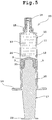
- Fig. 5 is a sectional view of a prefilled syringe in which the gasket shown in Fig. 1 is used.
- the medical appliance having a slidable coating layer of this embodiment is a gasket 1 for a syringe and liquid-tightly and slidably accommodated inside an outer cylinder 11 for the syringe as a medical member.
- the gasket 1 which is the medical appliance having a slidable coating layer of the present invention slidably contacts the inside of the outer cylinder of the syringe and has the coating layer 3 formed at a part thereof which contacts the syringe.
- the coating layer 3 is formed of the composition which does not contain the solid fine particles and contains the silicone-based resin which is the product of an addition reaction between the silicone having the vinyl groups and the silicone having the hydrogen groups bonded to the silicon atoms.
- the coating layer is formed of the above-described composition in the gasket of this embodiment, the coating layer has a more favorable sliding performance than a coating layer containing fine particles when the gasket slides at a low speed and in addition, the gasket does not stick to the syringe during the storage of the syringe. Therefore when the syringe is used, a smooth initial motion of the gasket can be accomplished, a rapid injection of a medical agent can be avoided, and the medical agent can be injected at a constant speed.
- the gasket has a merit in that there is no risk of floating of the fine particles in the medical agent solution.
- the gasket 1 of this embodiment is used for the syringe and liquid-tightly and slidably accommodated inside the outer cylinder 11 for the syringe.
- the gasket 1 has the coating layer 3 disposed at the part thereof where the coating layer 3 contacts the outer cylinder 11.
- the coating layer 3 contains the specific silicone resin to be described later.
- the gasket 1 has a body part (in other words, a core part) 2 and the coating layer 3 formed on at least the part, of an outer surface of the core part 2, where the coating layer 3 contacts an inner surface 12 of the outer cylinder 11.
- the coating layer 3 may be formed on the entire outer surface of the core part 2.
- the core part 2 of the gasket 1 for the syringe has a body portion 5 extending in an almost equal diameter, a tapered portion 6 disposed at a distal side of the body portion 5 and decreasing taperingly to the distal end thereof in its diameter, a plunger-mounting portion 4 disposed inside the body portion 5 from a proximal end thereof toward the distal end thereof; a distal-side annular rib 7a disposed on a side surface of a distal portion of the body portion 5, and a proximal-side annular rib 7b disposed on a side surface of a proximal portion of the body portion 5.
- Figs. 1 the core part 2 of the gasket 1 for the syringe
- the plunger-mounting portion 4 is formed as an approximately columnar concave portion which is disposed inside the body portion 5 and extends from the proximal end of the body portion 5 to a position in the vicinity of the distal end thereof.
- a screwing portion 8 capable of screwing on a screwing portion formed at a distal end of a plunger 17 is formed on a side surface of the above-described concave portion.
- a distal-end surface of the concave portion is formed almost flatly.
- the plunger-mounting portion 4 does not necessarily have to be formed as the screwing portion, but may be formed as an engaging portion which engages the distal portion of the plunger or may be formed in combination of the screwing portion and the engaging portion.
- An operation of mounting the plunger on the plunger-mounting portion is performed by screwing the plunger on the plunger-mounting portion. But a state in which the engaging portion engages the distal portion of the plunger may be held by an engaging portion formed separately from the screwing portion.
- the outer diameters of the annular ribs 7a and 7b are formed a little larger than the inner diameter of the outer cylinder 11 for use in the syringe. Therefore the annular ribs 7a and 7b compressively deform inside the outer cylinder 11.
- two annular ribs are formed, but one or three or more annular ribs may be formed.
- an elastic material is preferable.
- the elastic material to be used for the core part 2 is not limited to a specific one, but rubber materials (vulcanized rubber materials) such as natural rubber, isoprene rubber, butyl rubber, chloroprene rubber, nitrile-butadiene rubber, styrene-butadiene rubber, and silicone rubber; styrene-based elastomers and hydrogenated styrene-based elastomers; and mixtures of the styrene-based elastomers and polyolefins such as polyethylene, polypropylene, polybutene, and ⁇ -olefin copolymers; mixtures of the styrene-based elastomers and oil such as liquid paraffin, process oil; and mixtures of the styrene-based elastomers and powdery inorganic substances such as talc, cast, mica, and the like are listed
- polyvinyl chloride-based elastomers olefin-based elastomers, polyester-based elastomers, polyamide-based elastomers, polyurethane-based elastomers, and mixtures of these elastomers as materials composing the core part 2.
- the butyl rubber is preferable from the standpoint that it has elastic properties and can be sterilized by a high-pressure steam.
- the diene-based rubber and the styrene-based elastomers are preferable from the standpoint that these substances can be sterilized by ⁇ rays and electron beams.
- the coating layer 3 is formed at least at the portions where the annular ribs are disposed. More specifically, it is essential that the coating layer 3 is formed at the distal-side annular rib 7a and the proximal-side annular rib 7b.
- the coating layer 3 may be formed on the entire outer surface of the core part 2.
- the thickness of the coating layer 3 is favorably 1 to 30 ⁇ m and especially favorably to 3 to 10 ⁇ m. When the thickness of the coating layer 3 is not less than 1 ⁇ m, the coating layer 3 displays a necessary slidable performance. When the thickness of the coating layer 3 is not more than 30 ⁇ m, the coating layer 3 does not adversely affect the elasticity of the gasket.
- the coating layer 3 does not contain solid fine particles.
- the coating layer 3 is composed of a resin consisting of a material having a lower friction coefficient than the elastic material composing the core part 2.
- the resin of the coating layer 3 is silicone-based. It is possible to use both a solvent-based coating solution dissolved in an organic solvent and a water-based coating solution emulsified and dispersed in water. But in the case of the solvent-based coating solution, there is a concern about the influence thereof on the material of the gasket and about the presence of a residual solvent. Therefore the water-based coating solution is preferable because the water-based coating solution allows the gasket to have a higher aptitude than the solvent-based coating solution as a medical agent solution accommodation container.
- the coating layer 3 consists of the silicone to be obtained by hardening the reactant formed as a result of the addition reaction made between the silicone having the vinyl groups and the silicone having the hydrogen groups bonded to the silicon atoms by using the catalyst consisting of platinum and does not contain the solid fine particles. It is preferable that the silicone is thermosetting silicone or room-temperature curing silicone. From the standpoint of workability, the thermosetting silicone is more favorable.
- the coating layer 3 formed on the gasket of the present invention does not contain the "solid fine particle".
- the “solid fine particle” herein means a particle having a size to such an extent as to affect the roughness of the outer surface of the coating layer 3 when the coating layer 3 is formed. Specifically the “solid fine particle” means a particle having a diameter more than 10% of the thickness of the coating layer 3.
- the gasket 1 of the present invention has the above-described coating layer 3, the gasket 1 has a stable sliding performance without applying a lubricant to the sliding surface thereof and is capable of maintaining sealing performance inside the medical agent accommodation space. It is preferable that the initial sliding resistance value of the coating layer (in other words, gasket having coating layer) is not more than a maximum value of the dynamic sliding resistance value thereof.
- the gasket satisfying the above-described requirement is capable of starting favorable initial sliding and does not make an excessive initial movement.
- the coating layer 3 is obtained by applying a coating solution to the clean surface of the gasket and thereafter hardening it.
- a coating solution to the surface of the gasket
- spraying the coating solution to the surface of the gasket it is preferable to do so after heating a portion of the gasket to be coated to 60 to 120 degrees C. Thereby the coating solution can be rapidly fixed to the surface of the portion of the gasket to be coated without water repellence.
- the method of hardening the coating solution may be left at a normal temperature, but it is preferable to harden it by heating it.
- the method of thermally hardening the coating solution is not limited to a specific method, provided that the base material of the gasket is not modified or deformed. Hot-air drying, and a drying oven using infrared rays, and the like are exemplified.
- the method of hardening the coating solution can be carried out by known methods such as a method of using a decompression drier.
- the thickness of the coating layer is favorably 1 to 30 ⁇ m and more favorably 3 to 10 ⁇ m. Such a coating layer can be easily formed by appropriately controlling the concentration of a mixed solution, the dipping method, and the spraying method.
- the coating solution a water-based coating solution in which reactive silicone is emulsified and dispersed in water is preferable because as described above, the water-based coating solution easily allows the gasket to have an aptitude as the medical agent solution accommodation container.
- the coating solution of the present invention is characterized in that as the components thereof, the coating solution contains not only the reactive silicone which becomes a specific silicone-based resin after undergoing a reaction, but also a specific auxiliary agent for obtaining adhesion between the coating layer 3 and the core part 2 and enhancing the strength of the coating layer to prevent the coating layer 3 from peeling off the core part 2 or the coating layer 3 from being destroyed of itself when the gasket slides.
- the formula of the water-based coating solution is described below.
- the effective component of the coating solution is basically classified into three kinds.
- the coating solution is capable of containing additives as necessary.
- the component 1 the reactive silicone
- the component 2 the reaction catalyst and a reaction inhibitor for the component 1
- the component 3 the auxiliary agent.
- the component 1 is the combination of two kinds of components (component 1a, component 1b).
- the component 1a is an emulsion of polysiloxane containing the main component of the silicone of the coating layer 3.
- the polysiloxane has at least two vinyl groups in one molecule thereof.
- the emulsion of the polysiloxane having at least two vinyl groups in one molecule is prepared by dispersing the cyclic siloxane, the siloxane or silane having the vinyl group and an acid emulsifier in water and emulsifying and polymerizing the cyclic siloxane, the siloxane or the silane.
- cyclic siloxane hexamethylcyclotrisiloxane, octamethylcyclotetrasiloxane, decamethylcyclopentasiloxane, dodecamethylcyclohexasiloxane, hexaethylcyclotrisiloxane, hexaphenylcyclotrisiloxane, octaphenylcyclotetrasiloxane, triphenyltrimethylcyclotrisiloxane, and (3,3,3-trifluoropropyl)methylcyclotrisiloxane are listed.
- siloxane or the silane having the vinyl groups 1,3,5-trivinyl-1,3,5-trimethylcyclotrisiloxane, 1,3,5,7-tetravinyl-1,3,5,7-tetramethylcyclotetrasiloxane, pentavinylpentamethylcyclopentasiloxane, and tetrakis(vinyldimethylsiloxy)silane are listed.
- the mixing ratio (mole/mole) of the siloxane or the silane having the vinyl group to the cyclic siloxane is favorably 0.01 to 0.3 and more favorably 0.05 to 0.2.
- acid emulsifier a known acid-type anion surface active agent can be used.
- anion surface active agent organic sulfonates, higher alcohol sulfates, and higher alcohol ethoxylate sulfates are listed. Above all, straight-chain alkyl benzene sulfonic acid is preferable.
- a high-speed rotation type emulsification apparatus such as a homo-mixer type, a comb teeth type, and an intermittent jet stream generation type for rough emulsification. It is possible to use a pressure-type homogenizer for fine emulsification.
- the emulsification apparatus and a treatment condition it is preferable to so select the emulsification apparatus and a treatment condition as to obtain an emulsion of fine particles having an average diameter of about 1 ⁇ m in the rough emulsification and an emulsion of finer particles having an average diameter not exceeding 500nm in the fine emulsification.
- the average particle diameter is more than hundreds of nanometers after the fine emulsification finishes, a creaming phenomenon is liable to occur owing to coalescence of the fine particles, which is unpreferable in terms of the stability of the emulsion.
- the emulsion polymerization is performed by heating a finely emulsified product. It is preferable to heat the finely emulsified product at 60 to 80 degrees C and for five to eight hours.
- the fine particles in the emulsion obtained by the emulsion polymerization are the polysiloxane having at least two vinyl groups in one molecule thereof.
- the molecular weight of the polysiloxane is 60,000 to 400,000.
- the content of the vinyl group is 0.5 to 10 wt%.
- the emulsion concentration of the component 1a is preferably 30 to 60%.
- the component 1b is the emulsion of the polysiloxane containing the auxiliary component of the silicone of the coating layer 3 and reacts with the polysiloxane in the component 1a which is the main component of the silicone of the coating layer 3, thus playing the role of a crosslinking agent in the silicone of the coating layer 3.
- the polysiloxane has at least two the hydrogen groups bonded to silicon atom in one molecule thereof.
- the emulsion of the polysiloxane is prepared by dispersing the polysiloxane and the emulsifier in water and emulsifying the polysiloxane.
- the method of preparing the emulsion of the polysiloxane is carried out similarly to the dispersion emulsification method of the component 1a.
- polysiloxane having the two hydrogen groups bonded to silicon atoms in one molecule thereof polymethylhydrosiloxane having the trimethylsilyl group at its both terminals, poly(methylhydrosiloxane-dimethylsiloxane) having the trimethylsilyl group at its both terminals, polyethylhydrosiloxane having the trimethylsilyl group at its both terminals, and poly(methylhydrosiloxane-octylmethylsiloxane) having the trimethylsilyl group at its both terminals are listed.
- polydimethylsiloxane having the hydrogen group bonded to the silicon atom at its both terminals polyphenyl(dimethylhydro)siloxane having the hydrogen group bonded to the silicon atom at its both terminals
- poly(methylhydrosiloxane-phenylmethylsiloxane) having the hydrogen group bonded to the silicon atom at its both terminals to the polysiloxane so that these additives serve as a chain extender.
- the viscosity of the polysiloxane of the component 1b is favorably 2 to 1,000 mPa ⁇ S and more favorably 10 to 500 mPa ⁇ S.
- the molecular weight of the polysiloxane is favorably 500 to 50,000 and more favorably 1,000 to 20,000.
- the content of the hydrogen group bonded to the silicon atom is 100 mol% in the case of the polymethylhydrosiloxane having the trimethylsilyl group at its both terminals, 3 to 50 mol% in the case of the poly(methylhydrosiloxane-dimethylsiloxane) having the trimethylsilyl group at its both terminals and the poly(methylhydrosiloxane-octylmethylsiloxane) having the trimethylsilyl group at its both terminals, and 0.01 to 0.5 wt% in the case of the polysiloxane having the hydrogen group at its both terminals.
- the emulsion concentration of the component 1b is preferably 30 to 60%.
- the ratio (mole ratio) of the amount of the hydrogen group of the component 1b to the amount of the vinyl group of the component 1a is 0.5 to 2.0 and preferably 0.8 to 1.5.
- the component 2 serves as the catalyst in the reaction between the component 1a and the component 1b as one of its roles.
- the component 2 consists of the platinum-group metals for accelerating the hydrosilylation between the vinyl group of the component 1a and the hydrogen group of the component 1b.
- the platinum-group metal catalyst platinum group catalyst
- catalysts of platinum group, palladium group, and rhodium group are listed.
- the platinum group catalyst is preferable. Specifically, chloroplatinic acid, alcohol-modified chloroplatinic acid, complexes of chloroplatinic acid and ketones, complexes of the platinum and olefin, and complexes of the platinum and vinylsiloxane are listed.
- the main component of the component 1a and that of the component 1b are the polysiloxane.
- the complex of the platinum and the vinylsiloxane is preferable.
- a solution of a vinyl methyl cyclic siloxane which is a platinum-vinylsiloxane carbonyl cyclovinylmethylsiloxane complex, a solution of the polydimethylsiloxane which has the vinyl group at both terminals thereof and is a platinum-divinyltetramethyldisiloxane complex, and a solution of cyclic methylvinylsiloxane which is a platinum-cyclovinylmethylsiloxane complex are listed.
- the concentration of the platinum in these solutions is 1 to 3 wt%.
- the mixing amount of the component 2 to be contained in the coating solution is 1 to 1,000 ppm, favorably 5 to 500 ppm, and optimally 50 to 200 ppm for the polysiloxane of the component 1a in terms of the amount of the platinum.
- a preferable form of the component 2 is the emulsion to be obtained by dispersing the platinum-vinylsiloxane complex and the emulsifier in water and emulsifying the platinum-vinylsiloxane complex.
- the method of preparing the emulsion is the same as that of forming the emulsion of the component 1 to be obtained by carrying out the dispersion emulsification method.
- the component 2 serves as a reaction inhibitor in the reaction between the component 1a and the component 1b.
- the component 2 serves as an addition reaction inhibitor for obtaining stability by appropriately inhibiting the hydroxylation between the vinyl group of the component 1a and the hydrogen group of the component 1b while the coating solution is in storage and while an operation is being performed.
- the mixing amount of the addition reaction inhibitor to be contained in the coating solution is favorably 1 to 10 wt% and more favorably 0.1
- the component 3 consists of the auxiliary agent for preventing the coating layer 3 from peeling off the core part 2 and from being destroyed of itself.
- auxiliary agents of the component 3 alkyl alkoxysilane, phenylalkoxysilane, alkylphenoxysilane, aminoalkylalkoxysilane, and glycidoxyalkylalkoxysilane are preferable.
- the alkyl alkoxysilane has at least one alkyl group having a carbon number of 1 to 20 and at least one alkoxy group having a carbon number of 1 to 4.
- Preferable auxiliary agent of the component 3 includes methyltrimethoxysilane, methyltriethoxysilane, methyltriisobutoxysilane, methyltributoxysilane, methyl sec-trioctyloxysilane, isobutyltrimethoxysilane, cyclohexylmethyldimethoxysilane, diisopropyldimethoxysilane, propyltrimethoxysilane, diisobutyldimethoxysilane, n-octylmethoxysiloxane, ethyltrimethoxysilane, dimethyldimethoxysilane, octyltriethoxysilane, hexyltrimethoxysilane, hexyltriethoxysilane, octamethylcyclotetrasiloxane, methyltri(acryloyloxyethoxy)silane, octyltri
- the alkylphenoxysilane for example, methyltriphenoxysilane is preferable.
- phenoxyalkoxysilane phenyltrimethoxysilane, phenyltriethoxysilane, diphenyldimethoxysilane, and diphenyldiethoxysilane are preferable.
- the mixing amount of the above-described auxiliary agents to be contained in the coating solution is favorably 0.01 to 10 wt% and more favorably 0.1 to 5 wt% for the polysiloxane of the component 1a. When the mixing amount of these auxiliary agents is less than 0.1 wt%, it is difficult to obtain sufficient stability of the coating solution. When the mixing amount thereof is more than 10 wt%, the adhesion between the coating layer 3 and the core part 2 is insufficient, which is unpreferable.
- alkoxysilane having an ureido group (-NH-CO-NH 2 ) and alkoxysilane having an uraren group (-NH-CO-NH-) are exemplified.
- alkoxysilane having the ureido group (-NH-CO-NH 2 ) and the alkoxysilane having the uraren group (-NH-CO-NH-), ⁇ -ureidopropyltriethoxysilane, ⁇ -ureidopropyldiethoxymethylsilane, methylurarenpropyldimethoxymethylsilane, 3-[(2-ureidoethyl) ureil ]propyltrimethoxysilane, O C[NHCH 2 CH 2 CH 2 Si(OC 2 H 5 ) 3 ] 2 are listed.
- the ⁇ -ureidopropyltriethoxysilane is preferable because it is water-soluble and thus favorably dispersed in water in mixing it with other components of the coating solution to prepare the emulsion and in addition it can be easily obtained in a commercial circulation.
- the product of a reaction between the alkoxysilane having an amino group and dicarboxylic anhydride is preferable.
- the reaction product can be obtained by mixing the alkoxysilane having the amino group and the dicarboxylic anhydride with each other by setting the mixing ratio (mole ratio) of the amino group to the carboxylic acid to 0.5 to 2 and favorably 0.8 to 1.2 and allowing both substances to react with each other in a solvent for several hours to tens and several ours not less than a room temperature nor more than 90 degrees C.
- alcohols such as methanol, ethanol, and isopropanol
- ketones such as acetone and methyl ethyl ketone
- alkoxysilane having the amino group 3-aminopropyltriethoxysilane, 3-(2-aminoethyl)aminopropyltrimethoxysilane, 3-(2-aminoethyl)aminopropylmethyldimethoxysilane, 3-aminopropyltrimethoxysilane, and 3-phenylaminopropyltrimethoxysilane are preferable.
- the mixing amount of the above-described auxiliary agents to be contained in the coating solution is favorably 1 to 10 wt% and more favorably 3 to 8 wt% for the polysiloxane of the component 1a.
- the mixing amount of these auxiliary agents is less than 1 wt%, the adhesion between the coating layer 3 and the core part 2 is insufficient.
- the mixing amount of these auxiliary agents is more than 10 wt%, the flexibility and expansibility of the coating layer 3 deteriorate and the adhesion between the coating layer 3 and the core part 2 is insufficient, which is unpreferable.
- glycidoxyalkylalkoxysilane may be used.
- glycidoxyalkylalkoxysilane 3-glycidoxypropyltrimethoxysilane, 3-glycidoxypropyltriethoxysilane, 3-glycidoxypropylmethyldiethoxysilane, 3-glycidoxypropylmethyldimethoxysilane, and 2-(3,4-epoxycyclohexyl)ethyltrimethoxysilane are preferable.
- the mixing amount of the above-described auxiliary agents of the component 3 to be contained in the coating solution is favorably 1 to 10 wt% and more favorably 3 to 8 wt% for the polysiloxane of the component 1a.
- the mixing amount of these auxiliary agents to be contained therein is less than 1 wt%, the adhesion between the coating layer 3 and the core part 2 is insufficient.
- the mixing amount of these auxiliary agents to be contained therein is more than 10 wt%, the flexibility and expansibility of the coating layer 3 deteriorate and the adhesion between the coating layer 3 and the core part 2 is insufficient, which is unpreferable.
- additives such as a surface active agent, alcohol, and the like may be used.
- an anion surface active agent is preferable. Any anion surface active agents may be used. It is possible to use aliphatic monocarboxylates, polyoxyethylene alkylether carboxylates, N-acyl sarcosinates, N-acylglutamates, dialkyl sulfosuccinates, alkane sulfonates, alpha olefin sulfonates, straight chain alkylbenzene sulfonates, molecular chain alkylbenzene sulfonates, naphthalene sulfonate-formaldehyde condensate, alkylnaphthalene sulfonates, N-methyl-N-acyl taurine, alkyl sulfate, polyoxyethylene alkyl ether sulfates, fat and oil sulfates , alkyl phosphates, polyoxyethylene alkyl ether sulfates, and polyoxyethylene alkyl
- Nonionic surface active agents may also be used. Any nonionic surface active agents may be used. It is possible to use polyoxyethylene alkyl ether, polyoxyalkylene derivatives, polyoxyethylene alkylphenyl ether, polyoxyethylene sorbitan fatty acid ester, fatty acid alkanolamide, glycerin fatty acid ester, sorbitan fatty acid ester, polyoxyethylenealkylamine, and alkylalkanolamide.
- the syringe 10 of the present invention has the outer cylinder 11, the gasket 1 slidably accommodated inside the outer cylinder 11, and the plunger 17 which is mounted on the gasket 1or can be mounted on the gasket 1.
- the syringe 10 is constructed of the outer cylinder 11, for use in the syringe, which has a needle-mounting portion 15 disposed at the distal part thereof and a pair of opposed flanges 16 disposed at the proximal end thereof; the gasket 1, for use in the syringe, which is capable of liquid-tightly and airtightly sliding on an inner surface 12 of the outer cylinder 11 for use in the syringe; the plunger 17 which is mounted on the gasket 1 or can be mounted on the gasket 1 for use in the syringe; a sealing member 18 for sealing the needle-mounting portion 15 of the outer cylinder 11 for use in the syringe; and a medical agent accommodation portion 19, for accommodating a medical agent 26, which is formed among the sealing member 18, the inner surface 12 of the outer cylinder 11, and the gasket 1 for use in the syringe.
- the sealing member 18 may be of a type having a piercing portion into which a double ended needle can be directly inserted or may be of a type in which the medical agent cannot be discharged until the sealing member is removed.
- the gasket 1 has the above-described coating layer 3.
- the dynamic sliding resistance value of the gasket 1 when the gasket 1 slides at a low speed (100mm/minute) inside the outer cylinder 11 is not more than 20N.
- Such a low dynamic sliding resistance value can be obtained when the gasket 1 has the above-described coating layer 3.
- the dynamic sliding resistance value of the gasket 1 when the gasket 1 slides at the low speed (100mm/minute) inside the outer cylinder 11 is 1N to 20N.
- This medical appliance is a prefilled syringe 25 composed of the syringe 10 and the medical agent 26, as shown in Fig. 5 .
- the outer cylinder 11 for use in the syringe is a cylindrical member having the needle-mounting portion 15 disposed at the distal part thereof and the flange 16 disposed at the proximal end thereof.
- the outer cylinder 11 for use in the syringe is made of a material transparent or semitransparent. It is preferable that the outer cylinder 11 is made of a material having low oxygen permeability or low vapor permeability. It is preferable that the material forming the outer cylinder 11 has a glass transition point or a melting point not less than 110 degrees C.
- polystyrene As materials forming the outer cylinder 11, various general-purpose rigid plastic materials are preferable.
- Polyolefins such as polypropylene, polyethylene, poly (4-methylpentene-1), and cyclic polyolefin; polyesters such as polyethylene terephthalate, polyethylene naphthalate, and non-crystalline polyarylate; polystyrene; polyamide; polycarbonate, polyvinyl chloride; acrylic resin; an acrylonitrile-butadiene-styrene copolymer, and non-crystalline polyetherimide are preferable.
- the polypropylene, the poly (4-methylpentene-1), the cyclic polyolefin, the polyethylene naphthalate, and the non-crystalline polyetherimide are especially preferable because these resins are transparent and resistant to heat sterilization.
- These resins can be commonly used as materials to form containers capable of accommodating a medical agent in addition to the outer cylinder. It is also possible to use glass as a material to form the outer cylinder.
- the plunger 17 has a sectionally cross-shaped body portion 20 extended axially; a plunger-side screwing portion 21, disposed at the distal part thereof, which screws on the plunger-mounting portion 4; a disk-shaped gasket-supporting portion disposed between the plunger-side screwing portion 21 and the body portion 20; a disk portion 22, for pressing use, which is disposed at the proximal end of the body portion 20; and a disk-shaped rib formed midway on the body portion 20.
- the medical agent 26 is accommodated inside the syringe 10 of this embodiment.
- the medical agent 26 it is possible to use a medical agent solution and a solid agent such as a powdery medical agent and a freeze-dried medical agent.
- the medical agent solution, containing the surface active agent, which has a low viscosity and a high degree of penetration is preferable because although the medical agent solution makes it difficult to allow the gasket to have sliding property and to be liquid-tight, the medical agent solution can be preferably accommodated inside the syringe 10 which does not require silicone oil.
- the coating layer 3 is formed on the gasket 1 for the syringe at the part thereof which contacts the accommodated medical agent, it is possible to prevent the adsorption of the medical agent such as the medical agent solution which contains a component having a poor water solubility and has a high adsorbing property. Thus it is preferable to use such a medical agent.
- hard resins or semi-hard resins such as polyvinyl chloride, high-density polyethylene, polypropylene, polystyrene, polyethylene terephthalate, polycarbonate, acrylic resin, and the like.
- the above-described syringe is an example of the medical appliance which moves in contact with the inner surface of the medical member.
- This type of the medical appliance is not limited to the syringe, but may be any medical appliances, provided that they slidably contact the inside of the medical member.
- this type of the medical appliance may be a rubber stopper-provided vial container, a transfusion bag, a blood collection tube, and a decompression blood collection tube.
- the medical appliance of the present invention is not limited to the gasket for the syringe, but may be any of an O-ring, a stopper, a cover, and the like, provided that they slidably contact the medical member.
- the medical appliance of the present invention may be a rubber stopper of the vial container, a lid of the transfusion bag, and the like.
- the medical appliance of the present invention may be appliances which move in contact with the inner surface of the lumen.
- the medical appliance which moves in contact with the inner surface of the lumen includes a catheter, a guide wire, a blood vessel dilation appliance, and the like.
- the medical appliance of the present invention may be appliances which move in contact with the inner surface of the medical member and that of the lumen.
- the medical appliance which moves in contact with the inner surface of the lumen includes the catheter, the guide wire, and the blood vessel dilation appliance which are inserted into the catheter (for example, a guiding catheter) which is a medical member such that the distal portions thereof are guided to an intended portion of the lumen.
- Fig. 6 is a sectional view of one embodiment of the guide wire of the present invention.
- a guide wire 50 of this embodiment has an inner core 52 and a sliding film 53 enclosing the inner core 52.
- the guide wire of the embodiment shown in Fig. 6 has the inner core 52 composed of the body part 52a having a high rigidity and the distal part 52b, having a smaller diameter and a lower rigidity than the body part 52a, which is formed integrally with the body part 52a, a high radiographic visualization part 54 formed at the distal end of the inner core 52, and the sliding film 53 enclosing the entire inner core 52 on which the high radiographic visualization part 54 is formed.
- the inner core 52 of the guide wire 50 has the body part 52a and the distal part 52b and is integrally formed of an elastic metal.
- the diameter of the distal part 52b is so formed as to be smaller than the distal end of the body part 52a.
- the distal part 52b has a lower rigidity than the body part.
- the diameter of the distal part 52b may be so set as to become gradually smaller toward the distal end thereof from the distal end of the body part 52a.
- the inner core 52 is made of superelastic metals and stainless steels.
- the TiNi alloy is especially preferable.
- the outer diameter of the body part 52a of the inner core 52 is favorably 0.10 to 1.00mm and more favorably 0.15 to 0.40mm.
- the length of the body part 52a is favorably 1000 to 4000mm and more favorably 1500 to 3000mm.
- the buckling strength (yield stress when a load is applied) of the body part 52a is favorably 30 to 100Kg/mm 2 (22 degrees C) and more favorably 40 to 55 Kg/mm 2 .
- the restoration stress (yield stress when a load is removed) of the body part 52a is favorably 20 to 80Kg/mm 2 (22 degrees C) and more favorably 30 to 35Kg/mm 2 .
- the outer diameter of the distal part 52b of the inner core 52 is favorably 0.03 to 0.15mm and more favorably 0.05 to 0.10mm.
- the length of the distal part 52b is favorably 10 to 300mm and more favorably 50 to 150mm.
- the bending load of the distal part 52b is favorably 0.1 to 10g and more favorably 0.3 to 6.0g.
- the restoration load of the distal part 52b is favorably 0.1 to 10g and more favorably 0.3 to 6.0g.
- the diameter of the distal part of the inner core do not necessarily have to be set to the above-described range, but may be so set as to satisfy a part of the above-described range.
- the restoration stress of the body part and that of the distal part do not necessarily have to have an equal value, but it is preferable to make a device to allow the restoration stress of the body part and that of the distal part to be differentiated from each other by heat-treating them in different conditions so that the body part and the distal part have an appropriate wire diameter and thus an appropriate property respectively. That is, it is preferable to heat-treat the body part and the distal part in different conditions to allow the restoration stress of the body part to be high and that of the distal part to be flexible.
- the inner core 52 does not necessarily have to be composed of a single wire, but may be composed of a plurality of parallel or twisted wires so that the inner core 52 displays the above-described function, namely, a stepwise change or a continuous change.
- the high radiographic visualization part 54 is a metallic annular member, having a high radiographic visualization performance, which is fixed to the distal end of the inner core 52.
- the high radiographic visualization part 54 is formed of a pipe-shaped member.
- metals having high radiographic visualization performance gold, platinum, zinc, silver, bismuth, and tungsten are favorable. Gold is especially favorable.
- the high radiographic visualization part 54 is fixed to the distal end of the inner core 52 by mechanically crimping the high radiographic visualization part 54 to the distal end thereof or by soldering the high radiographic visualization part 54 to a plated or evaporated metal.
- the outer diameter of the high radiographic visualization part 54 is 0.20 to 0.90mm and preferably 0.25 to 0.40mm.
- the inner diameter thereof is 0.04 to 0.16mm and preferably 0.06 to 0.11mm.
- the length thereof is 1.00 to 10.00mm and preferably 1.5 to 4.0mm.
- the high radiographic visualization part 54 may be composed of a coiled thin wire formed of the above-described metal having a high radiographic visualization performance.
- the thin wire having a diameter of 0.02 to 0.10mm can be preferably used.
- the length of the high radiographic visualization part 54 to be wound on the distal end of the inner core is 1.0 to 10.0mm and preferably 1.5 to 4.0mm from the distal end thereof.
- the sliding film 53 coating the entire inner core 52 including the distal part thereof has an almost uniform outer diameter.
- the sliding film 53 has an almost uniform outer diameter to prevent the difference in level between the inner core 52 and the high radiographic visualization part 54 formed at the distal end of the inner core 52 from affecting the outer configuration of the guide wire 50.
- a film made of the same material as that of the coating layer 3 described on the gasket of the above-described embodiment can be preferably used as the sliding film 53.
- the outer diameter of the sliding film 53 is 0.25 to 1.04mm and preferably 0.30 to 0.64mm.
- the thickness of the inner core 52 at a part thereof disposed on the body part 52a of is 0.25 to 1.04mm and preferably 0.30 to 0.64mm.
- the distal end (the distal end of the sliding film 53) of the guide wire 50 has a curved surface, for example, a semispherical surface as shown in Fig. 6 to prevent a blood vessel wall from being damaged and improve the operability of the guide wire 50.
- the form of the inner core 52 is not limited to this one.
- the sliding film 53 may be so constructed as to cover a part of the inner core 52.
- the sliding film 53 may be so constructed as to cover only the distal part of the inner core 52 or only the body part of the inner core 52.
- the coating solution was prepared in accordance with methods used in the example 1 through 8 and the comparison example 1.
- 125g of octamethylcyclotetrasiloxane, 5g of 1,3,5,7-tetravinyltetramethylcyclotetrasiloxane, 2.5g of dodecylbenzenesulfonic acid, and 22.5g of water were measured and put in a 300mL tall beaker. Thereafter by using a homo mixer, the mixture was stirred at the number of rotations of 6,000 rpm for 10 minutes. Thereafter 100g of water was gradually added to the mixture at the number of rotations of 2,000 rpm to perform rough emulsification.
- the mixture was fed to a pressure-type homogenizer twice under the condition of a pressure of 300kg/cm 2 to perform fine emulsification.
- a finely emulsified product was allowed to make a reaction at 70 degrees C for six hours, the finely emulsified product was allowed to stand at 15 degrees C for 12 hours to perform emulsion polymerization.
- the pH was adjusted to 6.0, and the polymerization was completed.
- the molecular weight of the polysiloxane obtained by the polymerization was 330,000, and the content of the vinyl group was 4.5 wt%.
- the prepared product was used as the component 1a.
- the mixture was fed to the pressure-type homogenizer twice under the condition of the pressure of 300kg/cm 2 to perform fine emulsification.
- the prepared product was used as the component 1b.
- a polydimethylsiloxane solution (viscosity: 50 mPa ⁇ S, content of platinum: 3 wt%) consisting of a platinum-divinyltetramethyldisiloxane complex having the vinyl group at both terminals thereof, 7.5g of ethynyl cyclohexanol, 1.5g of the dodecylbenzenesulfonic acid, and 73.5g of water were measured and put in the 300mL tall beaker. Thereafter by using the homo mixer, the mixture was stirred at the number of rotations of 6,000 rpm for 10 minutes to perform rough emulsification. After defoaming was performed under a decreased pressure, the mixture was fed to the pressure-type homogenizer twice under the condition of the pressure of 300kg/cm 2 to perform fine emulsification. The prepared product was used as the component 2.
- Methyltriethoxysilane, ⁇ -ureidopropyltriethoxysilane, and ⁇ -glycidoxypropyltrimethoxysilane were used as the component 3.
- 100g of the component 1a, 3.4g of the component 1b, 0.17g of the component 2, 1g of the methyltriethoxysilane of the component 3, 1g of the ⁇ -ureidopropyltriethoxysilane, and 5g of the ⁇ -glycidoxypropyltrimethoxysilane, and 200g of water were mixed with one another to prepare a coating solution.
- a product was prepared in the same manner as that of the example 1.
- the prepared product was used as the component 1a.
- the molecular weight of the polysiloxane obtained by the polymerization was 310,000, and the content of the vinyl group was 5.4 wt%.
- Phenyltriethoxysilane, the ⁇ -ureidopropyltriethoxysilane, and the ⁇ -glycidoxypropyltrimethoxysilane were used as the component 3.
- 100g of the component 1a, 6.8g of the component 1b, 0.34g of the component 2, 1g of the phenyltriethoxysilane of the component 3, 5g of the ⁇ -ureidopropyltriethoxysilane, and 5g of the ⁇ -glycidoxypropyltrimethoxysilane, and 200g of water were mixed with one another to prepare a coating solution.
- a product was prepared in the same manner as that of the example 1.
- the prepared product was used as the component 1a.
- the molecular weight of the polysiloxane obtained by the polymerization was 350,000, and the content of the vinyl group was 3.8 wt%.
- the phenyltriethoxysilane, the ⁇ -ureidopropyltriethoxysilane, and the ⁇ -glycidoxypropyltrimethoxysilane were used as the component 3.
- 100g of the component 1a, 0.68g of the component 1b, 0.17g of the component 2, 1g of the phenyltriethoxysilane of the component 3, 5g of the ⁇ -ureidopropyltriethoxysilane, and 5g of the ⁇ -glycidoxypropyltrimethoxysilane, and 200g of water were mixed with one another to prepare a coating solution.
- the methyltriethoxysilane, the ⁇ -ureidopropyltriethoxysilane, and the ⁇ -glycidoxypropyltrimethoxysilane were used as the component 3.
- 100g of the component 1a, 3.4g of the component 1b, 0.17g of the component 2, 1g of the methyltriethoxysilane of the component 3, 5g of the reactant, 5g of the ⁇ -glycidoxypropyltrimethoxysilane, and 200g of water were mixed with one another to prepare a coating solution.
- the reactant obtained in preparing the component 3 of the example 5, the phenyltriethoxysilane, and the ⁇ -glycidoxypropyltrimethoxysilane were used as the component 3.
- the methyltriethoxysilane, the ⁇ -ureidopropyltriethoxysilane, and the ⁇ -glycidoxypropyltrimethoxysilane were used as the component 3.
- the reactant obtained in preparing the component 3 of the example 5, the methyltriethoxysilane, and the ⁇ -glycidoxypropyltrimethoxysilane were used as the component 3.
- 100g of the component 1a, 0.2g of the component 1b, 0.34g of the component 2, 1g of the methyltriethoxysilane of the component 3, 5g of the reactant, 5g of the ⁇ -glycidoxypropyltrimethoxysilane, and 200g of water were mixed with one another to prepare the coating solution.
- 125g of the octamethylcyclotetrasiloxane, 2.5g of the dodecylbenzenesulfonic acid, and 22.5g of water were measured and put in a 300mL tall beaker. Thereafter by using the homo mixer, the mixture was stirred at the number of rotations of 6,000 rpm for 10 minutes. Thereafter 100g of water was gradually added to the mixture at the number of rotations of 2,000 rpm to perform rough emulsification. After defoaming was performed under a decreased pressure, the mixture was fed to the pressure-type homogenizer twice under the condition of the pressure of 300kg/cm 2 to perform fine emulsification.
- the finely emulsified product was allowed to stand at 15 degrees C for 12 hours to perform emulsion polymerization. Thereafter by using the 10% sodium carbonate water solution, the pH was adjusted to 6.0, and the polymerization was completed. The molecular weight of the polysiloxane having the silanol group at both terminals thereof was 330,000.
- the prepared product was used as the component 1a.
- the component 1b was not used in the comparison example 1.
- the methyltriethoxysilane, the ⁇ -ureidopropyltriethoxysilane, and the ⁇ -glycidoxypropyltrimethoxysilane were used as the component 3.
- 100g of the component 1a, 1g of the component 2, 1g of the methyltriethoxysilane of the component 3, 1g of the ⁇ -ureidopropyltriethoxysilane, and 5g of the ⁇ -glycidoxypropyltrimethoxysilane, and 200g of water were mixed with one another to prepare the coating solution.
- the core parts, of gaskets for syringes, having the configuration shown in Figs. 1 and 2 were made by using butyl rubber.
- the core parts were formed by press-molding a vulcanizable rubber composition composed of butyl rubber to which an additive was added.
- the length of every core part was 20mm; the outer diameter of the core part at the distal-side and proximal-side annular ribs thereof was 30mm; the length between the center of the distal-side annular rib and that of the proximal-side annular rib was 10mm; the outer diameter of the core part at an equal-diameter portion thereof between the distal-side and proximal-side annular ribs was 27mm; the length (depth) of the plunger-mounting portion of the core part having a female screw at the inner side thereof was 10mm; and the inner diameter of a concave portion for connecting the plunger at its distal side and proximal side were 18mm and 21mm respectively.
- the gaskets made as described above at a room temperature and in a normal pressure were heat-treated at 90 degrees C for 30 minutes, the gaskets were rotated (300 rpm) on the respective axis thereof, and the coating solutions of the examples 1 through 8 and the comparison example 1 were sprayed to the gaskets respectively from the respective side surface thereof. Thereafter the gaskets were dried at 150 degrees C for 30 minutes. In this manner, the gaskets of the present invention were made. Thereafter to wash an extra coating liquid present on the gaskets, cleaning was performed with purified water having a temperature not less than 80 degrees C. The average thickness of the coating layer formed on the surface of each core member was about 10 ⁇ m.
- Polypropylene (produced by Japan Polychem Corporation) used as a material forming outer cylinders for syringes was injection-molded to form the outer cylinders for the syringes each having the configuration shown in Fig. 5 .
- the cylindrical portion of each of the outer cylinders for the syringes had an inner diameter of 29mm and a length of 121mm.
- the polypropylene (produced by Japan Polychem Corporation) used as a material of plungers was injection-molded to form the plungers each having the configuration shown in Fig. 5 .
- the sliding resistance value of each syringe was measured by using an autograph (model name: EZ-Test, manufactured by Shimazu Seisakusho Co., Ltd.). More specifically, with the distal end of each syringe and the proximal end of the plunger being fixed to a fixing portion of the autograph to which an object to be measured is fixed, the plungers were moved downward 60mm at a speed of 100mm/minute to measure the initial sliding resistance value and maximum sliding resistance value (N) of each syringe. Table 1 shows the results.
- the syringes using the gaskets of the examples 1 through 8 and the comparison example 1 had almost equal initial and maximum sliding resistance values.
- each of the syringes had a small difference between the initial sliding resistance value and maximum sliding resistance value thereof.
- the syringes were capable of discharging the medical agent solution safely and accurately.
- the initial and maximum sliding resistance values were not more than 10N were obtained.
- Example 2 Maximum sliding resistance value (N) 20 mm/min 30 mm/min 50 mm/min 100 mm/min 200 mm/min 500 mm/min
- Example 1 9.6 10.4 11.1 15.0 20.9 29.0
- Example 2 9.2 10.0 10.9 14.8 20.5 28.9
- Example 3 9.4 10.5 11.2 15.1 20.6 29.3
- Example 4 9.2 10.2 11.5 14.9 20.2 29.0
- Example 5 9.3 10.7 11.0 14.6 20.8 28.8
- Example 6 9.5 10.4 11.5 15.5 20.1 29.5
- Example 7 9.9 11.9 12.5 15.6 19.2 23.9
- Example 8 9.8 11.7 12.6 15.8 20.8 25.3 Comparison example 1 9.5 10.2 11.5 15.5 21.3 29.2
- the outer cylinders for the syringes having the configuration shown in Fig. 5 were formed.
- the cylindrical portion of each of the outer cylinders for the syringes had an inner diameter of 23mm and a length of 76mm.
- the polypropylene (produced by Japan Polychem Corporation) used as a material forming plungers was injection-molded to form the plungers each having the configuration shown in Fig. 5 .
- Table 3 shows the results. Table 3 Maximum sliding resistance value (N) 20 mm/min 50 mm/min 100 mm/min 500 mm/min Example 1 6.1 7.2 11.2 14.1 Example 2 6.2 7.4 11.3 14.3 Example 3 6.0 7.1 11.2 14.0 Example 4 6.4 7.3 11.5 14.6 Example 5 6.3 7.2 11.3 14.2 Example 6 6.1 7.0 11.2 14.1 Example 7 6.8 7.9 12.0 14.9 Example 8 7.0 8.0 12.4 15.0 Comparison example 1 6.0 7.3 11.4 14.2
- the polypropylene (produced by Japan Polychem Corporation) used as a material forming outer cylinders for syringes was injection-molded to form the outer cylinders for the syringes each having the configuration shown in Fig. 5 .
- the cylindrical portion of each of the outer cylinders for the syringes had an inner diameter of 29mm and a length of 121mm.
- the polypropylene (produced by Japan Polychem Corporation) used as a material of plungers was injection-molded to form the plungers each having the configuration shown in Fig. 5 .
- the number of samples used in the test was five. "Passed" was marked for samples of the examples and the comparison example in which all of the five samples passed inspection.
- the polypropylene (produced by Japan Polychem Corporation) used as a material forming outer cylinders for syringes was injection-molded to form the outer cylinders for the syringes each having the configuration shown in Fig. 5 .
- the cylindrical portion of each of the outer cylinders for the syringes had an inner diameter of 29mm and a length of 121mm.
- the polypropylene (produced by Japan Polychem Corporation) used as a material of plungers was injection-molded to form the plungers each having the configuration shown in Fig. 5 .
- the number of samples used in the test was five. "Passed" was marked for the samples of the examples and the comparison example in which all of the five samples passed inspection.
- the polypropylene (produced by Japan Polychem Corporation) used as a material forming outer cylinders for syringes was injection-molded to form the outer cylinders for the syringes each having the configuration shown in Fig. 5 .
- the cylindrical portion of each of the outer cylinders for the syringes had an inner diameter of 29mm and a length of 121mm.
- the polypropylene (produced by Japan Polychem Corporation) used as a material of plungers was injection-molded to form the plungers each having the configuration shown in Fig. 5 .
- the polypropylene (produced by Japan Polychem Corporation) used as a material forming outer cylinders for syringes was injection-molded to form the outer cylinders for the syringes each having the configuration shown in Fig. 5 .
- the cylindrical portion of each of the outer cylinders for the syringes had an inner diameter of 29mm and a length of 121mm.
- the polypropylene (produced by Japan Polychem Corporation) used as a material forming plungers was injection-molded to form the plungers each having the configuration shown in Fig. 5 .
- each syringe pump By using a syringe pump (TE-331 produced by Terumo Corporation), the flow rate accuracy of each syringe was evaluated.
- the polypropylene (produced by Japan Polychem Corporation) used as a material forming outer cylinders for syringes was injection-molded to form the outer cylinders for the syringes each having the configuration shown in Fig. 5 .
- the cylindrical portion of each of the outer cylinders for the syringes had an inner diameter of 29mm and a length of 121mm.
- the polypropylene (produced by Japan Polychem Corporation) used as a material forming plungers was injection-molded to form the plungers each having the configuration shown in Fig. 5 .
Landscapes
- Health & Medical Sciences (AREA)
- Engineering & Computer Science (AREA)
- Chemical & Material Sciences (AREA)
- Life Sciences & Earth Sciences (AREA)
- General Health & Medical Sciences (AREA)
- General Engineering & Computer Science (AREA)
- Veterinary Medicine (AREA)
- Public Health (AREA)
- Animal Behavior & Ethology (AREA)
- Hematology (AREA)
- Chemical Kinetics & Catalysis (AREA)
- Biomedical Technology (AREA)
- Anesthesiology (AREA)
- Mechanical Engineering (AREA)
- Epidemiology (AREA)
- Vascular Medicine (AREA)
- Heart & Thoracic Surgery (AREA)
- Materials Engineering (AREA)
- Wood Science & Technology (AREA)
- Organic Chemistry (AREA)
- Infusion, Injection, And Reservoir Apparatuses (AREA)
- Materials For Medical Uses (AREA)
- Media Introduction/Drainage Providing Device (AREA)
- Sealing Devices (AREA)
Claims (19)
- Dispositif médical comportant une couche de revêtement apte au glissement qui se déplace en contact avec une surface interne d'un élément médical ou celle d'une lumière et comporte ladite couche de revêtement apte au glissement formée en tant qu'une partie de celui-ci qui entre en contact avec ledit élément médical ou ladite lumière,
dans lequel ladite couche de revêtement apte au glissement est constituée d'une composition qui ne contient pas de fine particules solides et un composé organostannique, et contient une résine à base de silicone qui est un produit d'une réaction d'addition entre une émulsion de silicone comportant au moins deux groupes vinyle et une émulsion de silicone comportant au moins deux groupes hydrogène liés à des atomes de silicium,
caractérisé en ce que ledit silicone comportant au moins deux groupes vinyle est un polymère dans lequel ont été émulsionnés et polymérisés- un siloxane cyclique, et- un siloxane ou silane comportant le groupe vinyle,dans lequel ledit siloxane comportant les groupes vinyle est le 1,3,5-trivinyl-1,3,5-triméthylcyclotrisiloxane, le 1,3,5,7-tétravinyl-1,3,5,7-tétraméthylcyclotétrasiloxane, le pentavinylpentaméthylcyclopentasiloxane, ou ledit silane comportant le groupe vinyle est le tétrakis(vinyldiméthylsiloxy)silane,
dans lequel ladite résine à base de silicone de ladite composition est formée par hydrosilylation entre lesdits groupes vinyle dudit silicone et des groupes hydrogène liés auxdits atomes de silicium. - Dispositif médical comportant une couche de revêtement apte au glissement selon la revendication 1, dans lequel ledit siloxane cyclique est l'hexaméthylcyclotrisiloxane, l'octaméthylcyclotétrasiloxane, le décaméthylcyclopentasiloxane, le dodécaméthylcyclohexasiloxane, l'hexaéthylcyclotrisiloxane, l'hexaphénylcyclotrisiloxane, l'octaphénylcyclotétrasiloxane, le triphényltriméthylcyclotrisiloxane, ou le (3,3,3-trifluoropropyl)méthylcyclotrisiloxane.
- Dispositif médical comportant une couche de revêtement apte au glissement selon la revendication 1 ou 2, dans lequel ledit siloxane comportant des groupes vinyle est le 1,3,5,7-tétravinyl-1,3,5,7-tétraméthylcyclotétrasiloxane.
- Dispositif médical comportant une couche de revêtement apte au glissement selon l'une quelconque des revendications 1 à 3, dans lequel ladite composition contient un catalyseur à base de métal de la famille du platine.
- Dispositif médical comportant une couche de revêtement apte au glissement selon l'une quelconque des revendications 1 à 4, dans lequel ledit silicone comportant desdits groupes hydrogène liés auxdits atomes de silicium est un homopolymère ou un copolymère de polyméthylhydrosiloxane comportant un groupe triméthylsilyle à ses deux extrémités.
- Dispositif médical comportant une couche de revêtement apte au glissement selon l'une quelconque des revendications 1 à 5, dans lequel ledit silicone comportant desdits groupes hydrogène liés auxdits atomes de silicium est un homopolymère ou un copolymère de polydiméthylsiloxane comportant ledit groupe hydrogène lié audit atome de silicium à ses deux extrémités.
- Dispositif médical comportant une couche de revêtement apte au glissement selon l'une quelconque des revendications 1 à 6, dans lequel ladite composition contient un alkylalcoxysilane ou phénylalcoxysilane et en outre, un glycidoxyalkylalcoxysilane.
- Dispositif médical comportant une couche de revêtement apte au glissement selon l'une quelconque des revendications 1 à 7, dans lequel ladite composition contient un alcoxysilane comportant un groupe uréido ou un groupe urarène et/ou un produit formé par une réaction entre un alcoxysilane comportant un groupe amino et un anhydride carboxylique.
- Dispositif médical comportant une couche de revêtement apte au glissement selon l'une quelconque des revendications 1 à 8, dans lequel ladite résine à base de silicone est une résine à base de silicone thermodurcissable.
- Dispositif médical comportant une couche de revêtement apte au glissement selon l'une quelconque des revendications 1 à 9, dans lequel ladite couche de revêtement a une épaisseur de 1 à 30 µm.
- Dispositif médical comportant une couche de revêtement apte au glissement selon la revendication 10, dans lequel une valeur initiale de la résistance au glissement de ladite couche de revêtement n'excède pas une valeur maximale d'une valeur de la résistance au glissement dynamique de celle-ci.
- Dispositif médical comportant une couche de revêtement apte au glissement selon l'une quelconque des revendications 1 à 11, où ledit dispositif médical est fil guide ou un cathéter.
- Dispositif médical comportant une couche de revêtement apte au glissement selon l'une quelconque des revendications 1 à 11, dans lequel ledit élément médical est un cylindre externe pour une seringue ; ledit dispositif médical est un joint pour ladite seringue logé de façon apte au glissement à l'intérieur dudit cylindre externe pour ladite seringue ; et ledit joint comporte un corps de joint constitué d'un corps élastique et de ladite couche de revêtement apte au glissement formée sur une partie de celui-ci qui entre en contact avec au moins ledit cylindre externe pour ladite seringue.
- Dispositif médical comportant une couche de revêtement apte au glissement selon la revendication 13, dans lequel ledit élément médical et un cylindre externe en matière plastique pour une seringue, et ledit dispositif médical est un joint pour ledit cylindre externe en matière plastique pour ladite seringue.
- Dispositif médical selon la revendication 13 ou 14, dans lequel la couche de revêtement apte au glissement contient un polyméthylhydrosiloxane comportant le groupe triméthylsilyle à ses deux extrémités, un poly(méthylhydrosiloxane-diméthylsiloxane) comportant le groupe triméthylsilyle à ses deux extrémités, un polyéthylhydrosiloxane comportant le groupe triméthylsilyle à ses deux extrémités, ou un poly(méthylhydrosiloxane-octylméthylsiloxane) comportant le groupe triméthylsilyle à ses deux extrémités.
- Dispositif médical selon l'une quelconque des revendications 13 à 15, dans lequel ladite couche de revêtement apte au glissement est formée par application d'une solution de revêtement sur une surface dudit corps de joint et ensuite durcissement de ladite solution de revêtement, et ladite solution de revêtement contient un composant 1, un composant 2 et un composant 3,
dans lequel ledit composant 1 est une association d'un composant la et d'un composant 1b,
dans lequel ledit composant la est une émulsion de polysiloxane, ladite émulsion de polysiloxane est préparée par dispersion dudit siloxane cyclique, ledit siloxane comportant des groupes vinyle ou ledit silane comportant des groupes vinyle et un émulsifiant acide dans de l'eau et émulsification et polymérisation dudit siloxane cyclique et dudit siloxane comportant des groupes vinyle ou dudit silane comportant des groupes vinyle, et ledit siloxane comportant les groupes vinyle est le 1,3,5-trivinyl-1,3,5-triméthylcyclotrisiloxane, le 1,3,5,7-tétravinyl-1,3,5,7-tétraméthylcyclotétrasiloxane, ou le pentavinylpentaméthylcyclopentasiloxane, et ledit silane comportant des groupes vinyle est le tétrakis(vinyldiméthylsiloxy)silane,
dans lequel ledit composant 1b est une émulsion du polysiloxane, et ledit polysiloxane dudit composant 1b est un polyméthylhydrosiloxane comportant le groupe triméthylsilyle à ses deux extrémités, un poly(méthylhydrosiloxanediméthylsiloxane) comportant le groupe triméthylsilyle à ses deux extrémités, un polyéthylhydrosiloxane comportant le groupe triméthylsilyle à ses deux extrémités, ou un poly(méthylhydrosiloxane-octylméthylsiloxane) comportant le groupe triméthylsilyle à ses deux extrémités,
dans lequel ledit composant 2 contient un catalyseur, ledit catalyseur consiste en des métaux de la famille du platine pour accélérer l'hydrosilylation entre lesdits groupes vinyle dudit composant la et ledit groupe hydrogène dudit composant 1b,
dans lequel ledit composant 3 contient un alkylalcoxysilane, phénylalcoxysilane, alkylphénoxysilane, aminoalkylalcoxysilane ou glycidoxyalkylalcoxysilane. - Seringue comprenant un cylindre externe pour ladite seringue ; un joint, pour ladite seringue, qui est un dispositif médical comportant une couche de revêtement apte au glissement, selon l'une quelconque des revendications 13 à 16, logé de façon à pouvoir glisser à l'intérieur dudit cylindre externe ; et un piston qui est monté ou peut être monté sur ledit joint.
- Seringue selon la revendication 17, dans laquelle est introduite une solution d'agent médical.
- Seringue selon l'une quelconque des revendications 17 et 18, dans laquelle ledit cylindre externe est constitué de matière plastique.
Applications Claiming Priority (2)
| Application Number | Priority Date | Filing Date | Title |
|---|---|---|---|
| JP2010076814 | 2010-03-30 | ||
| PCT/JP2011/057679 WO2011122574A1 (fr) | 2010-03-30 | 2011-03-28 | Dispositif médical pourvu d'un revêtement coulissant, et seringue |
Publications (3)
| Publication Number | Publication Date |
|---|---|
| EP2554205A1 EP2554205A1 (fr) | 2013-02-06 |
| EP2554205A4 EP2554205A4 (fr) | 2015-10-28 |
| EP2554205B1 true EP2554205B1 (fr) | 2020-04-22 |
Family
ID=44712269
Family Applications (1)
| Application Number | Title | Priority Date | Filing Date |
|---|---|---|---|
| EP11762798.4A Active EP2554205B1 (fr) | 2010-03-30 | 2011-03-28 | Dispositif médical pourvu d'un revêtement coulissant, et seringue |
Country Status (5)
| Country | Link |
|---|---|
| US (1) | US8742032B2 (fr) |
| EP (1) | EP2554205B1 (fr) |
| JP (2) | JP5930959B2 (fr) |
| CN (1) | CN102821804B (fr) |
| WO (1) | WO2011122574A1 (fr) |
Cited By (1)
| Publication number | Priority date | Publication date | Assignee | Title |
|---|---|---|---|---|
| EP4069164A2 (fr) * | 2019-12-05 | 2022-10-12 | F. Hoffmann-La Roche AG | Seringue et procédé de test d'étanchéité |
Families Citing this family (26)
| Publication number | Priority date | Publication date | Assignee | Title |
|---|---|---|---|---|
| US8721603B2 (en) | 2008-01-15 | 2014-05-13 | West Pharmaceutical Services, Inc. | Syringe with co-molded hub and cannula |
| EP2692366B1 (fr) | 2011-03-30 | 2017-02-01 | Terumo Kabushiki Kaisha | Instrument médical pourvu d'une couche de revêtement coulissante, et seringue |
| US9434857B2 (en) * | 2011-11-15 | 2016-09-06 | Ethicon, Inc. | Rapid cure silicone lubricious coatings |
| LT3679922T (lt) * | 2012-06-01 | 2021-10-25 | Novartis Ag | Švirkštas |
| US8883245B2 (en) * | 2013-03-13 | 2014-11-11 | Ethicon, Inc. | Method of coating surgical needles |
| JP2014223149A (ja) * | 2013-05-15 | 2014-12-04 | 住友ゴム工業株式会社 | 注射器用ガスケット |
| MX383497B (es) * | 2013-10-28 | 2025-03-14 | Becton Dickinson Co | Tapon libre de fugas para un conjunto de jeringa que tiene fuerzas de sustentacion e inicial bajas. |
| JP6270265B2 (ja) * | 2014-02-05 | 2018-01-31 | 住友ゴム工業株式会社 | 医療用注射器、注射器に適用されるガスケットおよびその製造方法 |
| EP3127571A4 (fr) * | 2014-03-31 | 2017-11-29 | Terumo Kabushiki Kaisha | Joint de seringue et seringue équipée dudit joint |
| WO2016056038A1 (fr) | 2014-10-07 | 2016-04-14 | 有限会社コーキ・エンジニアリング | Caoutchouc de silicone médical coulissant, joint d'étanchéité utilisant ledit caoutchouc et seringue préremplie utilisant ledit joint d'étanchéité |
| CN107635527B (zh) | 2015-03-10 | 2021-04-23 | 里珍纳龙药品有限公司 | 无菌刺穿系统和方法 |
| WO2017002599A1 (fr) * | 2015-07-01 | 2017-01-05 | テルモ株式会社 | Agent de revêtement et surface d'un instrument médical traitée par l'agent de revêtement |
| WO2018218013A2 (fr) | 2017-05-24 | 2018-11-29 | Sio2 Medical Products, Inc. | Conditionnement pharmaceutique stérilisable pour formulations ophtalmiques |
| CA3005132A1 (fr) | 2015-11-18 | 2017-05-26 | Sio2 Medical Products, Inc. | Seringue revetue pour des formulations ophtalmiques contenant un antagoniste du vegf |
| EP3437665A4 (fr) * | 2016-03-31 | 2019-11-20 | Terumo Kabushiki Kaisha | Substance liquide pour revêtement de dispositif médical et dispositif médical doté d'un film de revêtement de glissement |
| EP3524295B1 (fr) | 2016-10-05 | 2021-06-16 | Terumo Kabushiki Kaisha | Dispositif d'administration de médicament liquide et procédé de commande pour dispositif d'administration de médicament liquide |
| EP3557596B1 (fr) | 2016-12-19 | 2024-04-03 | Tanaka Kikinzoku Kogyo K.K. | Contact de type bande et son procédé de fabrication |
| KR102540409B1 (ko) | 2017-05-05 | 2023-06-09 | 리제너론 파아마슈티컬스, 인크. | 자동 주사기 |
| FR3075056A1 (fr) | 2017-12-14 | 2019-06-21 | Etablissement Francais Du Sang | Dispositif d'injection cryoresistant pret a l'emploi |
| DE102018122001A1 (de) * | 2018-09-10 | 2020-03-12 | Schott Ag | Packmittel mit Gleitschicht und Verfahren für pharmazeutische und kosmetische Stoffe und Zubereitung zu dessen Herstellung |
| JP7074642B2 (ja) | 2018-10-29 | 2022-05-24 | 信越化学工業株式会社 | シリコーンエマルジョン組成物 |
| CN113438956A (zh) | 2019-03-26 | 2021-09-24 | 泰尔茂株式会社 | 注射器用帽、注射器组装体以及预灌装注射器 |
| JP7018619B2 (ja) | 2019-09-30 | 2022-02-14 | 株式会社朝日ラバー | アミノ変性界面改質層を有する摺動性ゴム材、及びそれを製造する方法 |
| USD950720S1 (en) * | 2020-11-20 | 2022-05-03 | Becton, Dickinson And Company | Medical stopper |
| EP4395587A1 (fr) * | 2021-09-03 | 2024-07-10 | Nicoventures Trading Limited | Réservoir pour un dispositif de recharge, dispositif et procédé pour recharger un article d'un système de fourniture d'aérosol, buse pour distribution de fluide, et article rechargeable pour un système de fourniture d'aérosol électronique |
| USD1007676S1 (en) | 2021-11-16 | 2023-12-12 | Regeneron Pharmaceuticals, Inc. | Wearable autoinjector |
Family Cites Families (27)
| Publication number | Priority date | Publication date | Assignee | Title |
|---|---|---|---|---|
| JPS60181162A (ja) | 1984-02-28 | 1985-09-14 | Toray Silicone Co Ltd | 硬化性オルガノポリシロキサン組成物 |
| JPS6232970A (ja) | 1985-08-01 | 1987-02-12 | セイコーエプソン株式会社 | シリンジ |
| US4968766A (en) * | 1989-01-12 | 1990-11-06 | Dow Corning Corporation | Fluorosilicone compounds and compositions for adhesive release liners |
| DE69127614T2 (de) * | 1990-11-17 | 1998-04-09 | Santen Pharma Co Ltd | Spritzenzylinder mit zwei kammern |
| JPH06183555A (ja) * | 1992-12-22 | 1994-07-05 | Siegel:Kk | 緩衝装置 |
| US5352378A (en) * | 1993-05-27 | 1994-10-04 | Minnesota Mining And Manufacturing Company | Nonflammable lubricious composition |
| JP3248322B2 (ja) * | 1993-11-15 | 2002-01-21 | 信越化学工業株式会社 | 塗膜形成性シリコーン樹脂組成物及びシリコーン樹脂成型体 |
| DE19753766A1 (de) * | 1997-12-04 | 1999-06-17 | Schott Glas | Länglicher Kunststoff-Hohlkörper und Verfahren zu seiner Herstellung |
| US6200627B1 (en) * | 1998-03-17 | 2001-03-13 | Becton, Dickinson And Company | Low silicone glass prefillable syringe |
| US6243938B1 (en) * | 1998-03-17 | 2001-06-12 | Becton, Dickinson And Company | Low silicone plastic prefillable syringe |
| GB9808890D0 (en) | 1998-04-28 | 1998-06-24 | Dow Corning | Silicone coated textile fabrics |
| US7176269B2 (en) | 2000-07-25 | 2007-02-13 | Mitsui Chemicals, Inc. | Curable composition and its use |
| JP2002037947A (ja) | 2000-07-25 | 2002-02-06 | Mitsui Chemicals Inc | 硬化性組成物およびその用途 |
| JP2002089717A (ja) | 2000-09-14 | 2002-03-27 | Terumo Corp | ガスケット |
| US7332227B2 (en) | 2003-03-14 | 2008-02-19 | Becton, Dickinson And Company | Non-volatile lubricant system for medical devices |
| JP4481587B2 (ja) | 2003-04-25 | 2010-06-16 | テルモ株式会社 | シリンジ |
| CN1715325A (zh) * | 2004-06-30 | 2006-01-04 | 威海威高创新有限公司 | 一次性注射器活塞用软聚氯乙烯塑料 |
| US7648487B2 (en) * | 2004-09-28 | 2010-01-19 | Nipro Corporation | Syringe |
| JP4708013B2 (ja) | 2004-12-15 | 2011-06-22 | テルモ株式会社 | シリンジ |
| US7943242B2 (en) * | 2006-03-30 | 2011-05-17 | Becton, Dickinson And Company | Sealing members, articles using the same and methods of reducing sticktion |
| JP2008000287A (ja) | 2006-06-21 | 2008-01-10 | Terumo Corp | 医療用具コーティング用摺動性組成物および摺動性被膜保有医療用具 |
| JP2008144024A (ja) | 2006-12-08 | 2008-06-26 | Daikin Ind Ltd | 硬化性ポリマー組成物 |
| EP2097471B1 (fr) | 2006-12-21 | 2014-09-10 | Dow Corning Corporation | Polymères à double durcissement et leurs procédés de préparation et d'utilisation |
| JP2008268493A (ja) * | 2007-04-19 | 2008-11-06 | Bando Chem Ind Ltd | 電子写真装置用クリーニングブレード及びその製造方法 |
| GB0715376D0 (en) | 2007-08-07 | 2007-09-19 | Smith & Nephew | Coating |
| JP5060873B2 (ja) | 2007-08-24 | 2012-10-31 | 東レ・ダウコーニング株式会社 | シリコーン系感圧接着剤組成物および感圧接着テープもしくはシート |
| WO2009084646A1 (fr) * | 2007-12-28 | 2009-07-09 | Terumo Kabushiki Kaisha | Joint d'étanchéité pour une seringue et seringue comprenant le joint d'étanchéité |
-
2011
- 2011-03-28 EP EP11762798.4A patent/EP2554205B1/fr active Active
- 2011-03-28 CN CN201180015853.7A patent/CN102821804B/zh active Active
- 2011-03-28 WO PCT/JP2011/057679 patent/WO2011122574A1/fr not_active Ceased
- 2011-03-28 JP JP2012508320A patent/JP5930959B2/ja active Active
-
2012
- 2012-09-27 US US13/628,833 patent/US8742032B2/en active Active
-
2016
- 2016-04-26 JP JP2016088074A patent/JP2016152998A/ja active Pending
Non-Patent Citations (1)
| Title |
|---|
| None * |
Cited By (1)
| Publication number | Priority date | Publication date | Assignee | Title |
|---|---|---|---|---|
| EP4069164A2 (fr) * | 2019-12-05 | 2022-10-12 | F. Hoffmann-La Roche AG | Seringue et procédé de test d'étanchéité |
Also Published As
| Publication number | Publication date |
|---|---|
| WO2011122574A1 (fr) | 2011-10-06 |
| EP2554205A4 (fr) | 2015-10-28 |
| JP5930959B2 (ja) | 2016-06-08 |
| CN102821804A (zh) | 2012-12-12 |
| JP2016152998A (ja) | 2016-08-25 |
| JPWO2011122574A1 (ja) | 2013-07-08 |
| US20130030380A1 (en) | 2013-01-31 |
| US8742032B2 (en) | 2014-06-03 |
| CN102821804B (zh) | 2015-06-10 |
| EP2554205A1 (fr) | 2013-02-06 |
Similar Documents
| Publication | Publication Date | Title |
|---|---|---|
| EP2554205B1 (fr) | Dispositif médical pourvu d'un revêtement coulissant, et seringue | |
| EP2692366B1 (fr) | Instrument médical pourvu d'une couche de revêtement coulissante, et seringue | |
| EP2226088B1 (fr) | Joint d'étanchéité pour une seringue et seringue comprenant le joint d'étanchéité | |
| EP1870117B1 (fr) | Composition de revêtement d'application médicale et appareil médical | |
| EP3437665A1 (fr) | Substance liquide pour revêtement de dispositif médical et dispositif médical doté d'un film de revêtement de glissement | |
| EP2004249B1 (fr) | Éléments d'étanchéité, articles associés et procédés permettant de réduire l'adhérence | |
| US20170014576A1 (en) | Gasket for use in syringe and syringe having gasket | |
| WO2023135884A1 (fr) | Joint d'étanchéité pour seringue et seringue le comprenant |
Legal Events
| Date | Code | Title | Description |
|---|---|---|---|
| PUAI | Public reference made under article 153(3) epc to a published international application that has entered the european phase |
Free format text: ORIGINAL CODE: 0009012 |
|
| 17P | Request for examination filed |
Effective date: 20120907 |
|
| AK | Designated contracting states |
Kind code of ref document: A1 Designated state(s): AL AT BE BG CH CY CZ DE DK EE ES FI FR GB GR HR HU IE IS IT LI LT LU LV MC MK MT NL NO PL PT RO RS SE SI SK SM TR |
|
| DAX | Request for extension of the european patent (deleted) | ||
| RA4 | Supplementary search report drawn up and despatched (corrected) |
Effective date: 20150924 |
|
| RIC1 | Information provided on ipc code assigned before grant |
Ipc: F16J 15/16 20060101ALI20150918BHEP Ipc: A61M 5/315 20060101AFI20150918BHEP |
|
| STAA | Information on the status of an ep patent application or granted ep patent |
Free format text: STATUS: EXAMINATION IS IN PROGRESS |
|
| 17Q | First examination report despatched |
Effective date: 20180719 |
|
| REG | Reference to a national code |
Ref country code: DE Ref legal event code: R079 Ref document number: 602011066403 Country of ref document: DE Free format text: PREVIOUS MAIN CLASS: A61M0005315000 Ipc: A61L0029080000 |
|
| GRAP | Despatch of communication of intention to grant a patent |
Free format text: ORIGINAL CODE: EPIDOSNIGR1 |
|
| STAA | Information on the status of an ep patent application or granted ep patent |
Free format text: STATUS: GRANT OF PATENT IS INTENDED |
|
| RIC1 | Information provided on ipc code assigned before grant |
Ipc: C09D 183/14 20060101ALI20190923BHEP Ipc: F16J 15/3284 20160101ALI20190923BHEP Ipc: A61L 29/08 20060101AFI20190923BHEP Ipc: A61M 5/315 20060101ALI20190923BHEP |
|
| INTG | Intention to grant announced |
Effective date: 20191022 |
|
| GRAJ | Information related to disapproval of communication of intention to grant by the applicant or resumption of examination proceedings by the epo deleted |
Free format text: ORIGINAL CODE: EPIDOSDIGR1 |
|
| STAA | Information on the status of an ep patent application or granted ep patent |
Free format text: STATUS: EXAMINATION IS IN PROGRESS |
|
| GRAR | Information related to intention to grant a patent recorded |
Free format text: ORIGINAL CODE: EPIDOSNIGR71 |
|
| GRAS | Grant fee paid |
Free format text: ORIGINAL CODE: EPIDOSNIGR3 |
|
| STAA | Information on the status of an ep patent application or granted ep patent |
Free format text: STATUS: GRANT OF PATENT IS INTENDED |
|
| GRAA | (expected) grant |
Free format text: ORIGINAL CODE: 0009210 |
|
| STAA | Information on the status of an ep patent application or granted ep patent |
Free format text: STATUS: THE PATENT HAS BEEN GRANTED |
|
| INTC | Intention to grant announced (deleted) | ||
| INTG | Intention to grant announced |
Effective date: 20200228 |
|
| AK | Designated contracting states |
Kind code of ref document: B1 Designated state(s): AL AT BE BG CH CY CZ DE DK EE ES FI FR GB GR HR HU IE IS IT LI LT LU LV MC MK MT NL NO PL PT RO RS SE SI SK SM TR |
|
| REG | Reference to a national code |
Ref country code: GB Ref legal event code: FG4D |
|
| REG | Reference to a national code |
Ref country code: CH Ref legal event code: EP |
|
| REG | Reference to a national code |
Ref country code: DE Ref legal event code: R096 Ref document number: 602011066403 Country of ref document: DE |
|
| REG | Reference to a national code |
Ref country code: IE Ref legal event code: FG4D |
|
| REG | Reference to a national code |
Ref country code: AT Ref legal event code: REF Ref document number: 1259226 Country of ref document: AT Kind code of ref document: T Effective date: 20200515 |
|
| REG | Reference to a national code |
Ref country code: LT Ref legal event code: MG4D |
|
| REG | Reference to a national code |
Ref country code: NL Ref legal event code: MP Effective date: 20200422 |
|
| PG25 | Lapsed in a contracting state [announced via postgrant information from national office to epo] |
Ref country code: IS Free format text: LAPSE BECAUSE OF FAILURE TO SUBMIT A TRANSLATION OF THE DESCRIPTION OR TO PAY THE FEE WITHIN THE PRESCRIBED TIME-LIMIT Effective date: 20200822 Ref country code: FI Free format text: LAPSE BECAUSE OF FAILURE TO SUBMIT A TRANSLATION OF THE DESCRIPTION OR TO PAY THE FEE WITHIN THE PRESCRIBED TIME-LIMIT Effective date: 20200422 Ref country code: NL Free format text: LAPSE BECAUSE OF FAILURE TO SUBMIT A TRANSLATION OF THE DESCRIPTION OR TO PAY THE FEE WITHIN THE PRESCRIBED TIME-LIMIT Effective date: 20200422 Ref country code: SE Free format text: LAPSE BECAUSE OF FAILURE TO SUBMIT A TRANSLATION OF THE DESCRIPTION OR TO PAY THE FEE WITHIN THE PRESCRIBED TIME-LIMIT Effective date: 20200422 Ref country code: PT Free format text: LAPSE BECAUSE OF FAILURE TO SUBMIT A TRANSLATION OF THE DESCRIPTION OR TO PAY THE FEE WITHIN THE PRESCRIBED TIME-LIMIT Effective date: 20200824 Ref country code: NO Free format text: LAPSE BECAUSE OF FAILURE TO SUBMIT A TRANSLATION OF THE DESCRIPTION OR TO PAY THE FEE WITHIN THE PRESCRIBED TIME-LIMIT Effective date: 20200722 Ref country code: GR Free format text: LAPSE BECAUSE OF FAILURE TO SUBMIT A TRANSLATION OF THE DESCRIPTION OR TO PAY THE FEE WITHIN THE PRESCRIBED TIME-LIMIT Effective date: 20200723 Ref country code: LT Free format text: LAPSE BECAUSE OF FAILURE TO SUBMIT A TRANSLATION OF THE DESCRIPTION OR TO PAY THE FEE WITHIN THE PRESCRIBED TIME-LIMIT Effective date: 20200422 |
|
| REG | Reference to a national code |
Ref country code: AT Ref legal event code: MK05 Ref document number: 1259226 Country of ref document: AT Kind code of ref document: T Effective date: 20200422 |
|
| PG25 | Lapsed in a contracting state [announced via postgrant information from national office to epo] |
Ref country code: BG Free format text: LAPSE BECAUSE OF FAILURE TO SUBMIT A TRANSLATION OF THE DESCRIPTION OR TO PAY THE FEE WITHIN THE PRESCRIBED TIME-LIMIT Effective date: 20200722 Ref country code: RS Free format text: LAPSE BECAUSE OF FAILURE TO SUBMIT A TRANSLATION OF THE DESCRIPTION OR TO PAY THE FEE WITHIN THE PRESCRIBED TIME-LIMIT Effective date: 20200422 Ref country code: HR Free format text: LAPSE BECAUSE OF FAILURE TO SUBMIT A TRANSLATION OF THE DESCRIPTION OR TO PAY THE FEE WITHIN THE PRESCRIBED TIME-LIMIT Effective date: 20200422 Ref country code: LV Free format text: LAPSE BECAUSE OF FAILURE TO SUBMIT A TRANSLATION OF THE DESCRIPTION OR TO PAY THE FEE WITHIN THE PRESCRIBED TIME-LIMIT Effective date: 20200422 |
|
| PG25 | Lapsed in a contracting state [announced via postgrant information from national office to epo] |
Ref country code: AL Free format text: LAPSE BECAUSE OF FAILURE TO SUBMIT A TRANSLATION OF THE DESCRIPTION OR TO PAY THE FEE WITHIN THE PRESCRIBED TIME-LIMIT Effective date: 20200422 |
|
| REG | Reference to a national code |
Ref country code: DE Ref legal event code: R097 Ref document number: 602011066403 Country of ref document: DE |
|
| PG25 | Lapsed in a contracting state [announced via postgrant information from national office to epo] |
Ref country code: EE Free format text: LAPSE BECAUSE OF FAILURE TO SUBMIT A TRANSLATION OF THE DESCRIPTION OR TO PAY THE FEE WITHIN THE PRESCRIBED TIME-LIMIT Effective date: 20200422 Ref country code: AT Free format text: LAPSE BECAUSE OF FAILURE TO SUBMIT A TRANSLATION OF THE DESCRIPTION OR TO PAY THE FEE WITHIN THE PRESCRIBED TIME-LIMIT Effective date: 20200422 Ref country code: SM Free format text: LAPSE BECAUSE OF FAILURE TO SUBMIT A TRANSLATION OF THE DESCRIPTION OR TO PAY THE FEE WITHIN THE PRESCRIBED TIME-LIMIT Effective date: 20200422 Ref country code: IT Free format text: LAPSE BECAUSE OF FAILURE TO SUBMIT A TRANSLATION OF THE DESCRIPTION OR TO PAY THE FEE WITHIN THE PRESCRIBED TIME-LIMIT Effective date: 20200422 Ref country code: DK Free format text: LAPSE BECAUSE OF FAILURE TO SUBMIT A TRANSLATION OF THE DESCRIPTION OR TO PAY THE FEE WITHIN THE PRESCRIBED TIME-LIMIT Effective date: 20200422 Ref country code: CZ Free format text: LAPSE BECAUSE OF FAILURE TO SUBMIT A TRANSLATION OF THE DESCRIPTION OR TO PAY THE FEE WITHIN THE PRESCRIBED TIME-LIMIT Effective date: 20200422 Ref country code: RO Free format text: LAPSE BECAUSE OF FAILURE TO SUBMIT A TRANSLATION OF THE DESCRIPTION OR TO PAY THE FEE WITHIN THE PRESCRIBED TIME-LIMIT Effective date: 20200422 Ref country code: ES Free format text: LAPSE BECAUSE OF FAILURE TO SUBMIT A TRANSLATION OF THE DESCRIPTION OR TO PAY THE FEE WITHIN THE PRESCRIBED TIME-LIMIT Effective date: 20200422 |
|
| PG25 | Lapsed in a contracting state [announced via postgrant information from national office to epo] |
Ref country code: PL Free format text: LAPSE BECAUSE OF FAILURE TO SUBMIT A TRANSLATION OF THE DESCRIPTION OR TO PAY THE FEE WITHIN THE PRESCRIBED TIME-LIMIT Effective date: 20200422 Ref country code: SK Free format text: LAPSE BECAUSE OF FAILURE TO SUBMIT A TRANSLATION OF THE DESCRIPTION OR TO PAY THE FEE WITHIN THE PRESCRIBED TIME-LIMIT Effective date: 20200422 |
|
| PLBE | No opposition filed within time limit |
Free format text: ORIGINAL CODE: 0009261 |
|
| STAA | Information on the status of an ep patent application or granted ep patent |
Free format text: STATUS: NO OPPOSITION FILED WITHIN TIME LIMIT |
|
| 26N | No opposition filed |
Effective date: 20210125 |
|
| PG25 | Lapsed in a contracting state [announced via postgrant information from national office to epo] |
Ref country code: SI Free format text: LAPSE BECAUSE OF FAILURE TO SUBMIT A TRANSLATION OF THE DESCRIPTION OR TO PAY THE FEE WITHIN THE PRESCRIBED TIME-LIMIT Effective date: 20200422 |
|
| PG25 | Lapsed in a contracting state [announced via postgrant information from national office to epo] |
Ref country code: MC Free format text: LAPSE BECAUSE OF FAILURE TO SUBMIT A TRANSLATION OF THE DESCRIPTION OR TO PAY THE FEE WITHIN THE PRESCRIBED TIME-LIMIT Effective date: 20200422 |
|
| REG | Reference to a national code |
Ref country code: CH Ref legal event code: PL |
|
| REG | Reference to a national code |
Ref country code: BE Ref legal event code: MM Effective date: 20210331 |
|
| PG25 | Lapsed in a contracting state [announced via postgrant information from national office to epo] |
Ref country code: LU Free format text: LAPSE BECAUSE OF NON-PAYMENT OF DUE FEES Effective date: 20210328 Ref country code: LI Free format text: LAPSE BECAUSE OF NON-PAYMENT OF DUE FEES Effective date: 20210331 Ref country code: CH Free format text: LAPSE BECAUSE OF NON-PAYMENT OF DUE FEES Effective date: 20210331 Ref country code: IE Free format text: LAPSE BECAUSE OF NON-PAYMENT OF DUE FEES Effective date: 20210328 |
|
| PG25 | Lapsed in a contracting state [announced via postgrant information from national office to epo] |
Ref country code: BE Free format text: LAPSE BECAUSE OF NON-PAYMENT OF DUE FEES Effective date: 20210331 |
|
| PG25 | Lapsed in a contracting state [announced via postgrant information from national office to epo] |
Ref country code: HU Free format text: LAPSE BECAUSE OF FAILURE TO SUBMIT A TRANSLATION OF THE DESCRIPTION OR TO PAY THE FEE WITHIN THE PRESCRIBED TIME-LIMIT; INVALID AB INITIO Effective date: 20110328 Ref country code: CY Free format text: LAPSE BECAUSE OF FAILURE TO SUBMIT A TRANSLATION OF THE DESCRIPTION OR TO PAY THE FEE WITHIN THE PRESCRIBED TIME-LIMIT Effective date: 20200422 |
|
| PG25 | Lapsed in a contracting state [announced via postgrant information from national office to epo] |
Ref country code: MK Free format text: LAPSE BECAUSE OF FAILURE TO SUBMIT A TRANSLATION OF THE DESCRIPTION OR TO PAY THE FEE WITHIN THE PRESCRIBED TIME-LIMIT Effective date: 20200422 |
|
| PG25 | Lapsed in a contracting state [announced via postgrant information from national office to epo] |
Ref country code: TR Free format text: LAPSE BECAUSE OF FAILURE TO SUBMIT A TRANSLATION OF THE DESCRIPTION OR TO PAY THE FEE WITHIN THE PRESCRIBED TIME-LIMIT Effective date: 20200422 |
|
| PG25 | Lapsed in a contracting state [announced via postgrant information from national office to epo] |
Ref country code: MT Free format text: LAPSE BECAUSE OF FAILURE TO SUBMIT A TRANSLATION OF THE DESCRIPTION OR TO PAY THE FEE WITHIN THE PRESCRIBED TIME-LIMIT Effective date: 20200422 |
|
| PGFP | Annual fee paid to national office [announced via postgrant information from national office to epo] |
Ref country code: DE Payment date: 20250128 Year of fee payment: 15 |
|
| PGFP | Annual fee paid to national office [announced via postgrant information from national office to epo] |
Ref country code: FR Payment date: 20250210 Year of fee payment: 15 |
|
| PGFP | Annual fee paid to national office [announced via postgrant information from national office to epo] |
Ref country code: GB Payment date: 20260209 Year of fee payment: 16 |