EP2554859A1 - Fluiddynamische lagerungseinheit und montageverfahren dafür - Google Patents
Fluiddynamische lagerungseinheit und montageverfahren dafür Download PDFInfo
- Publication number
- EP2554859A1 EP2554859A1 EP11762780A EP11762780A EP2554859A1 EP 2554859 A1 EP2554859 A1 EP 2554859A1 EP 11762780 A EP11762780 A EP 11762780A EP 11762780 A EP11762780 A EP 11762780A EP 2554859 A1 EP2554859 A1 EP 2554859A1
- Authority
- EP
- European Patent Office
- Prior art keywords
- outer member
- thrust bearing
- radial
- inner member
- fluid dynamic
- Prior art date
- Legal status (The legal status is an assumption and is not a legal conclusion. Google has not performed a legal analysis and makes no representation as to the accuracy of the status listed.)
- Granted
Links
- 239000012530 fluid Substances 0.000 title claims abstract description 199
- 238000000034 method Methods 0.000 title claims description 82
- 230000002093 peripheral effect Effects 0.000 claims abstract description 228
- 239000002184 metal Substances 0.000 claims abstract description 124
- 229910052751 metal Inorganic materials 0.000 claims abstract description 124
- 239000010687 lubricating oil Substances 0.000 claims description 86
- 238000003825 pressing Methods 0.000 claims description 30
- 230000008569 process Effects 0.000 claims description 30
- 239000000853 adhesive Substances 0.000 claims description 29
- 230000001070 adhesive effect Effects 0.000 claims description 29
- 239000011148 porous material Substances 0.000 claims description 28
- 238000005096 rolling process Methods 0.000 claims description 19
- 238000009472 formulation Methods 0.000 claims description 12
- 239000000203 mixture Substances 0.000 claims description 12
- RYGMFSIKBFXOCR-UHFFFAOYSA-N Copper Chemical compound [Cu] RYGMFSIKBFXOCR-UHFFFAOYSA-N 0.000 claims description 11
- 229910052802 copper Inorganic materials 0.000 claims description 11
- 239000010949 copper Substances 0.000 claims description 11
- IYRDVAUFQZOLSB-UHFFFAOYSA-N copper iron Chemical compound [Fe].[Cu] IYRDVAUFQZOLSB-UHFFFAOYSA-N 0.000 claims description 10
- 229920005989 resin Polymers 0.000 description 67
- 239000011347 resin Substances 0.000 description 67
- 238000000465 moulding Methods 0.000 description 34
- 239000000463 material Substances 0.000 description 28
- 239000003921 oil Substances 0.000 description 27
- 230000004048 modification Effects 0.000 description 22
- 238000012986 modification Methods 0.000 description 22
- 230000009471 action Effects 0.000 description 16
- 238000001746 injection moulding Methods 0.000 description 13
- 239000004033 plastic Substances 0.000 description 13
- XEEYBQQBJWHFJM-UHFFFAOYSA-N Iron Chemical compound [Fe] XEEYBQQBJWHFJM-UHFFFAOYSA-N 0.000 description 8
- 238000002347 injection Methods 0.000 description 8
- 239000007924 injection Substances 0.000 description 8
- 230000036316 preload Effects 0.000 description 6
- 230000009467 reduction Effects 0.000 description 6
- 230000008961 swelling Effects 0.000 description 6
- 238000005299 abrasion Methods 0.000 description 5
- 230000007246 mechanism Effects 0.000 description 5
- 229920006324 polyoxymethylene Polymers 0.000 description 5
- 238000007789 sealing Methods 0.000 description 5
- 238000004513 sizing Methods 0.000 description 5
- 230000003068 static effect Effects 0.000 description 5
- 238000009423 ventilation Methods 0.000 description 5
- 229920000106 Liquid crystal polymer Polymers 0.000 description 4
- 239000004977 Liquid-crystal polymers (LCPs) Substances 0.000 description 4
- 229910052742 iron Inorganic materials 0.000 description 4
- 238000004519 manufacturing process Methods 0.000 description 4
- 229930182556 Polyacetal Natural products 0.000 description 3
- 238000007906 compression Methods 0.000 description 3
- 230000006835 compression Effects 0.000 description 3
- 238000001816 cooling Methods 0.000 description 3
- 230000007423 decrease Effects 0.000 description 3
- 230000002542 deteriorative effect Effects 0.000 description 3
- 238000010438 heat treatment Methods 0.000 description 3
- 238000004381 surface treatment Methods 0.000 description 3
- 239000004952 Polyamide Substances 0.000 description 2
- 239000004734 Polyphenylene sulfide Substances 0.000 description 2
- 229910000831 Steel Inorganic materials 0.000 description 2
- 230000008901 benefit Effects 0.000 description 2
- 239000003795 chemical substances by application Substances 0.000 description 2
- 238000005097 cold rolling Methods 0.000 description 2
- 238000004891 communication Methods 0.000 description 2
- 230000001010 compromised effect Effects 0.000 description 2
- 230000008878 coupling Effects 0.000 description 2
- 238000010168 coupling process Methods 0.000 description 2
- 238000005859 coupling reaction Methods 0.000 description 2
- 239000000945 filler Substances 0.000 description 2
- 229920002647 polyamide Polymers 0.000 description 2
- 229920000069 polyphenylene sulfide Polymers 0.000 description 2
- 239000000843 powder Substances 0.000 description 2
- 230000002940 repellent Effects 0.000 description 2
- 239000005871 repellent Substances 0.000 description 2
- 229910001220 stainless steel Inorganic materials 0.000 description 2
- 239000010935 stainless steel Substances 0.000 description 2
- 239000010959 steel Substances 0.000 description 2
- 230000003245 working effect Effects 0.000 description 2
- 239000004593 Epoxy Substances 0.000 description 1
- 231100000597 Sick building syndrome Toxicity 0.000 description 1
- 230000004323 axial length Effects 0.000 description 1
- 239000004566 building material Substances 0.000 description 1
- 239000012141 concentrate Substances 0.000 description 1
- 239000004020 conductor Substances 0.000 description 1
- 230000003247 decreasing effect Effects 0.000 description 1
- 230000006866 deterioration Effects 0.000 description 1
- 230000000694 effects Effects 0.000 description 1
- 238000004540 process dynamic Methods 0.000 description 1
- 238000004080 punching Methods 0.000 description 1
- 239000012779 reinforcing material Substances 0.000 description 1
- 208000008842 sick building syndrome Diseases 0.000 description 1
- 239000000243 solution Substances 0.000 description 1
Images














Classifications
-
- H—ELECTRICITY
- H02—GENERATION; CONVERSION OR DISTRIBUTION OF ELECTRIC POWER
- H02K—DYNAMO-ELECTRIC MACHINES
- H02K5/00—Casings; Enclosures; Supports
- H02K5/04—Casings or enclosures characterised by the shape, form or construction thereof
- H02K5/16—Means for supporting bearings, e.g. insulating supports or means for fitting bearings in the bearing-shields
- H02K5/167—Means for supporting bearings, e.g. insulating supports or means for fitting bearings in the bearing-shields using sliding-contact or spherical cap bearings
- H02K5/1672—Means for supporting bearings, e.g. insulating supports or means for fitting bearings in the bearing-shields using sliding-contact or spherical cap bearings radially supporting the rotary shaft at both ends of the rotor
-
- F—MECHANICAL ENGINEERING; LIGHTING; HEATING; WEAPONS; BLASTING
- F16—ENGINEERING ELEMENTS AND UNITS; GENERAL MEASURES FOR PRODUCING AND MAINTAINING EFFECTIVE FUNCTIONING OF MACHINES OR INSTALLATIONS; THERMAL INSULATION IN GENERAL
- F16C—SHAFTS; FLEXIBLE SHAFTS; ELEMENTS OR CRANKSHAFT MECHANISMS; ROTARY BODIES OTHER THAN GEARING ELEMENTS; BEARINGS
- F16C17/00—Sliding-contact bearings for exclusively rotary movement
- F16C17/10—Sliding-contact bearings for exclusively rotary movement for both radial and axial load
- F16C17/102—Sliding-contact bearings for exclusively rotary movement for both radial and axial load with grooves in the bearing surface to generate hydrodynamic pressure
- F16C17/107—Sliding-contact bearings for exclusively rotary movement for both radial and axial load with grooves in the bearing surface to generate hydrodynamic pressure with at least one surface for radial load and at least one surface for axial load
-
- F—MECHANICAL ENGINEERING; LIGHTING; HEATING; WEAPONS; BLASTING
- F16—ENGINEERING ELEMENTS AND UNITS; GENERAL MEASURES FOR PRODUCING AND MAINTAINING EFFECTIVE FUNCTIONING OF MACHINES OR INSTALLATIONS; THERMAL INSULATION IN GENERAL
- F16C—SHAFTS; FLEXIBLE SHAFTS; ELEMENTS OR CRANKSHAFT MECHANISMS; ROTARY BODIES OTHER THAN GEARING ELEMENTS; BEARINGS
- F16C33/00—Parts of bearings; Special methods for making bearings or parts thereof
- F16C33/02—Parts of sliding-contact bearings
- F16C33/04—Brasses; Bushes; Linings
- F16C33/06—Sliding surface mainly made of metal
- F16C33/10—Construction relative to lubrication
- F16C33/1025—Construction relative to lubrication with liquid, e.g. oil, as lubricant
- F16C33/106—Details of distribution or circulation inside the bearings, e.g. details of the bearing surfaces to affect flow or pressure of the liquid
- F16C33/107—Grooves for generating pressure
-
- F—MECHANICAL ENGINEERING; LIGHTING; HEATING; WEAPONS; BLASTING
- F16—ENGINEERING ELEMENTS AND UNITS; GENERAL MEASURES FOR PRODUCING AND MAINTAINING EFFECTIVE FUNCTIONING OF MACHINES OR INSTALLATIONS; THERMAL INSULATION IN GENERAL
- F16C—SHAFTS; FLEXIBLE SHAFTS; ELEMENTS OR CRANKSHAFT MECHANISMS; ROTARY BODIES OTHER THAN GEARING ELEMENTS; BEARINGS
- F16C33/00—Parts of bearings; Special methods for making bearings or parts thereof
- F16C33/02—Parts of sliding-contact bearings
- F16C33/04—Brasses; Bushes; Linings
- F16C33/06—Sliding surface mainly made of metal
- F16C33/12—Structural composition; Use of special materials or surface treatments, e.g. for rust-proofing
- F16C33/128—Porous bearings, e.g. bushes of sintered alloy
-
- F—MECHANICAL ENGINEERING; LIGHTING; HEATING; WEAPONS; BLASTING
- F16—ENGINEERING ELEMENTS AND UNITS; GENERAL MEASURES FOR PRODUCING AND MAINTAINING EFFECTIVE FUNCTIONING OF MACHINES OR INSTALLATIONS; THERMAL INSULATION IN GENERAL
- F16C—SHAFTS; FLEXIBLE SHAFTS; ELEMENTS OR CRANKSHAFT MECHANISMS; ROTARY BODIES OTHER THAN GEARING ELEMENTS; BEARINGS
- F16C33/00—Parts of bearings; Special methods for making bearings or parts thereof
- F16C33/02—Parts of sliding-contact bearings
- F16C33/04—Brasses; Bushes; Linings
- F16C33/06—Sliding surface mainly made of metal
- F16C33/14—Special methods of manufacture; Running-in
-
- F—MECHANICAL ENGINEERING; LIGHTING; HEATING; WEAPONS; BLASTING
- F16—ENGINEERING ELEMENTS AND UNITS; GENERAL MEASURES FOR PRODUCING AND MAINTAINING EFFECTIVE FUNCTIONING OF MACHINES OR INSTALLATIONS; THERMAL INSULATION IN GENERAL
- F16C—SHAFTS; FLEXIBLE SHAFTS; ELEMENTS OR CRANKSHAFT MECHANISMS; ROTARY BODIES OTHER THAN GEARING ELEMENTS; BEARINGS
- F16C43/00—Assembling bearings
- F16C43/02—Assembling sliding-contact bearings
-
- F—MECHANICAL ENGINEERING; LIGHTING; HEATING; WEAPONS; BLASTING
- F16—ENGINEERING ELEMENTS AND UNITS; GENERAL MEASURES FOR PRODUCING AND MAINTAINING EFFECTIVE FUNCTIONING OF MACHINES OR INSTALLATIONS; THERMAL INSULATION IN GENERAL
- F16C—SHAFTS; FLEXIBLE SHAFTS; ELEMENTS OR CRANKSHAFT MECHANISMS; ROTARY BODIES OTHER THAN GEARING ELEMENTS; BEARINGS
- F16C2220/00—Shaping
- F16C2220/02—Shaping by casting
- F16C2220/04—Shaping by casting by injection-moulding
-
- F—MECHANICAL ENGINEERING; LIGHTING; HEATING; WEAPONS; BLASTING
- F16—ENGINEERING ELEMENTS AND UNITS; GENERAL MEASURES FOR PRODUCING AND MAINTAINING EFFECTIVE FUNCTIONING OF MACHINES OR INSTALLATIONS; THERMAL INSULATION IN GENERAL
- F16C—SHAFTS; FLEXIBLE SHAFTS; ELEMENTS OR CRANKSHAFT MECHANISMS; ROTARY BODIES OTHER THAN GEARING ELEMENTS; BEARINGS
- F16C2220/00—Shaping
- F16C2220/20—Shaping by sintering pulverised material, e.g. powder metallurgy
-
- F—MECHANICAL ENGINEERING; LIGHTING; HEATING; WEAPONS; BLASTING
- F16—ENGINEERING ELEMENTS AND UNITS; GENERAL MEASURES FOR PRODUCING AND MAINTAINING EFFECTIVE FUNCTIONING OF MACHINES OR INSTALLATIONS; THERMAL INSULATION IN GENERAL
- F16C—SHAFTS; FLEXIBLE SHAFTS; ELEMENTS OR CRANKSHAFT MECHANISMS; ROTARY BODIES OTHER THAN GEARING ELEMENTS; BEARINGS
- F16C2226/00—Joining parts; Fastening; Assembling or mounting parts
- F16C2226/10—Force connections, e.g. clamping
- F16C2226/12—Force connections, e.g. clamping by press-fit, e.g. plug-in
-
- F—MECHANICAL ENGINEERING; LIGHTING; HEATING; WEAPONS; BLASTING
- F16—ENGINEERING ELEMENTS AND UNITS; GENERAL MEASURES FOR PRODUCING AND MAINTAINING EFFECTIVE FUNCTIONING OF MACHINES OR INSTALLATIONS; THERMAL INSULATION IN GENERAL
- F16C—SHAFTS; FLEXIBLE SHAFTS; ELEMENTS OR CRANKSHAFT MECHANISMS; ROTARY BODIES OTHER THAN GEARING ELEMENTS; BEARINGS
- F16C2226/00—Joining parts; Fastening; Assembling or mounting parts
- F16C2226/10—Force connections, e.g. clamping
- F16C2226/14—Force connections, e.g. clamping by shrink fit, i.e. heating and shrinking part to allow assembly
-
- F—MECHANICAL ENGINEERING; LIGHTING; HEATING; WEAPONS; BLASTING
- F16—ENGINEERING ELEMENTS AND UNITS; GENERAL MEASURES FOR PRODUCING AND MAINTAINING EFFECTIVE FUNCTIONING OF MACHINES OR INSTALLATIONS; THERMAL INSULATION IN GENERAL
- F16C—SHAFTS; FLEXIBLE SHAFTS; ELEMENTS OR CRANKSHAFT MECHANISMS; ROTARY BODIES OTHER THAN GEARING ELEMENTS; BEARINGS
- F16C2226/00—Joining parts; Fastening; Assembling or mounting parts
- F16C2226/30—Material joints
- F16C2226/40—Material joints with adhesive
-
- F—MECHANICAL ENGINEERING; LIGHTING; HEATING; WEAPONS; BLASTING
- F16—ENGINEERING ELEMENTS AND UNITS; GENERAL MEASURES FOR PRODUCING AND MAINTAINING EFFECTIVE FUNCTIONING OF MACHINES OR INSTALLATIONS; THERMAL INSULATION IN GENERAL
- F16C—SHAFTS; FLEXIBLE SHAFTS; ELEMENTS OR CRANKSHAFT MECHANISMS; ROTARY BODIES OTHER THAN GEARING ELEMENTS; BEARINGS
- F16C2360/00—Engines or pumps
- F16C2360/46—Fans, e.g. ventilators
-
- H—ELECTRICITY
- H02—GENERATION; CONVERSION OR DISTRIBUTION OF ELECTRIC POWER
- H02K—DYNAMO-ELECTRIC MACHINES
- H02K2205/00—Specific aspects not provided for in the other groups of this subclass relating to casings, enclosures, supports
- H02K2205/03—Machines characterised by thrust bearings
-
- H—ELECTRICITY
- H02—GENERATION; CONVERSION OR DISTRIBUTION OF ELECTRIC POWER
- H02K—DYNAMO-ELECTRIC MACHINES
- H02K2213/00—Specific aspects, not otherwise provided for and not covered by codes H02K2201/00 - H02K2211/00
- H02K2213/09—Machines characterised by the presence of elements which are subject to variation, e.g. adjustable bearings, reconfigurable windings, variable pitch ventilators
Definitions
- the present invention relates to a fluid dynamic bearing device in which an inner member is supported in a freely rotatable manner with a dynamic pressure action of a lubricating oil, which is generated in bearing gaps between the inner member and an outer member.
- a bearing is incorporated in motors to be mounted to electric devices such as an exhaust fan, and the bearing supports a rotary shaft in a freely rotatable manner.
- a rolling bearing including: an outer race; an inner race; a plurality of rolling elements arranged between the inner and outer races; and a retainer for retaining the rolling elements (for example, Patent Literature 1).
- the fluid dynamic bearing device described in Patent Literature 2 includes: an outer member (first bearing member) including a first bearing ring (12), and a pair of first bearing plates (16 and 20) projecting toward an inner diameter side from the first bearing ring (12); and an inner member (second bearing member) including a cylindrical second bearing ring (14) to be mounted to a rotary shaft, and a second bearing plate (18) fixed to an outer peripheral surface of the second bearing ring (14) .
- the outer member includes a large number of components, and hence processing cost and assembly cost for those components are high.
- cost reduction is difficult to achieve, and in addition, it is difficult to process dynamic pressure generating grooves with high accuracy.
- a second invention of the present application has been made to achieve an object to provide a fluid dynamic bearing device which is excellent in quietness, can be manufactured with high accuracy and at low cost, and facilitates setting of the thrust bearing gaps and assembly, and to provide an assembly method for the fluid dynamic bearing device.
- the inner member is made of a sintered metal, and hence plastic flow generated at the time of forming the dynamic pressure generating grooves in the radial bearing surface of the inner member through a rolling process can be absorbed by inner pores of the sintered metal. Thus, surface swelling caused by the plastic flow is suppressed, and hence the dynamic pressure generating grooves can be formed with high accuracy. Further, the dynamic pressure generating grooves in each of the thrust bearing surfaces of the outer member are formed by the pressing process, and hence the dynamic pressure generating grooves can be formed with high accuracy and at low cost.
- An end surface of the cylindrical portion of the first outer member is positioned to be lower than an outside surface of the radial portion of the second outer member.
- a copper-iron based material is used as a material for the sintered metal of the part of the inner member which forms the bearing surfaces, and a formulation ratio of the copper is set to range from 20% to 80%.
- a formulation ratio of the copper is set to range from 20% to 80%.
- the bringing the one of the thrust bearing surfaces of the projecting portion of the inner member into abutment against the thrust bearing surface of the first outer member comprises: setting the first outer member on a placing surface of a first jig having the placing surface and a bottom surface; inserting the projecting portion of the inner member into the first outer member so that the projecting portion of the inner member abuts against the thrust bearing surface of the first outer member; press-fitting, after the inserting, the sleeve portion to the projecting portion until an end surface of the sleeve portion abuts against the bottom surface of the first jig; setting, after the press-fitting, a set of the first outer member and the inner member on a placing surface of a second jig, the second jig having the placing surface and a bottom surface different from the placing surface and the bottom surface of the first jig; and bringing the end surface of the sleeve portion into abutment against the bottom surface of the second jig so
- an assembly method further comprises injecting an adhesive under a state in which the second outer member is pushed in the first outer member, the adhesive for performing fixation while securing sealability can be injected efficiently.
- the thrust bearing gaps are easily set in the fluid dynamic bearing device, and the fluid dynamic bearing device itself is easily assembled. Further, the outside outermember and the inside outer member can be press-fitted to each other without compromising accuracy. Still further, in terms of securing sealability, this structure is suitable forcontinuous injection of an adhesive for bonding.
- An indicator for identifying the rotational direction is provided on an outer surface of the fluid dynamic bearing device.
- the assembly method comprises: accommodating the inner member within the outside outer member and the inside outer member; fitting the outside outer member and the inside outer member to each other; temporarily fixing the outside outer member and the inside outer member to each other with the projection portion under the state in which the thrust bearing gaps are set; and then injecting and curing the adhesive.
- the thrust bearing gaps can be easily set in the fluid dynamic bearing device, and the fluid dynamic bearing device itself can be easily assembled.
- assembly operability can be enhanced.
- a copper-iron based material is used as a material for a sintered metal of the projecting portion 10a as a part forming a bearing surface of the inner member 10, and a formulation ratio of copper is set to range from 20% to 80%.
- a formulation ratio of copper is set to range from 20% to 80%.
- the formulation ratio of the copper is less than 20%, there arise problems with formability of the dynamic pressure generating grooves and lubricity therein. Meanwhile, when the formulation ratio of the copper exceeds 80%, it is difficult to secure abrasion resistance.
- a surface pore rate of the sintered metal is set to range from 2% to 20%.
- the dynamic pressure generating grooves 11a, 12a, and 13a are each formed in a herringbone pattern, and are provided for a uni-directional rotation.
- the first outer member 20a and the second outer member 20b have surfaces different from each other in hue, which can prevent failures in assembly.
- surfaces different from each other in hue for example, materials different from each other in hue are used, or surface treatment is performed.
- the spring 7 applies an axial preload to both the fluid dynamic bearing devices 4 and 4.
- the elastic force of the spring 7 is set within such a range that the outer member 20 is prevented from being rotated and the outer member 20 and the inner member 10 are prevented from coming into sliding contact with each other.
- the elastic force of the spring 7 be set approximately to range from 20% to 80% of a load capacity of the dynamic pressure action generated in the thrust bearing gaps T.
- the inner member 10 is provided in the axial direction between both the inside surfaces 22 and 23 of the outer member 20.
- the inner member 10 is prevented from dropping off from an inner periphery of the outer member 20.
- the inner member 10 and the outer member 20 are prevented from being separated from each other, and hence the fluid dynamic bearing device 4 can be integrally treated.
- the fluid dynamic bearing device 4 is more easily mounted to the rotary shaft 2 and the housing 5.
- the inner member 10 is formed of an integral piece of the projecting portion 10a and the sleeve portion 10b, and is made of a sintered metal. Other structural details are the same as those in the first embodiment.
- the outer member 20 is formed integrally by a pressing process on a single plate member. As illustrated in FIG. 11(b) , the outer member 20 comprises the cylindrical portion 20a1 and the radial portions 20a2 and 20a3 respectively formed at both ends of the cylindrical portion 20a1, and is formed into a substantially C-shape in vertical cross-section.
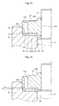
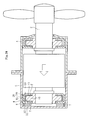
- a jig B illustrated in FIG. 12 (a) is a first jig, which has an upper surface to serve as a placing surface 30 and a bottom portion 31 recessed with respect to the placing surface 30 by a dimension D.
- the first outer member 20a is set on the placing surface 30 of the first jig B in a manner that the radial portion 20a2 of the first outer member 20a is directed downward and an outside surface of the radial portion 20a2 is held in abutment against the placing surface 30.
- the projecting portion 10a of the inner member 10 is inserted into the first outer member 20a so that the side surface 12 thereof is brought into abutment against the inside surface 22 of the first outer member 20a.
- FIG. 12(a) illustrates such a press-fitting completion state.
- the radial portion 20a2 of the first outer member 20a is directed downward and inserted along the guide surface 34 of the fixing jig F so that the outside surface of the radial portion 20a2 is held in abutment against the placing surface 30. In this way, the first outer member 20a is set. Then, after the inner peripheral surface 10c of the sleeve portion 10b of the inner member 10 is fitted to the guide surface 37 of the moving jig G, the inner member 10 is inserted into the first outer member 20a so that the side surface 12 thereof is brought into abutment against the inside surface 22 of the first outer member 20a. In this state, an appropriate load is applied downward to the inner member 10.
- the moving jig G is raised so that the shoulder surface 36 of the moving jig G is brought into abutment against the lower end surface of the sleeve portion 10b of the inner member 10 that has been inserted in the first outer member 20a. From this position, which is to serve as a reference position, the moving jig G is further raised so that the inner member 10 is spaced apart from the first outer member 20a. Then, the moving jig G is stopped at a position at which the total amount ⁇ of the thrust bearing gaps T on both the sides is secured. At this position, a static state is maintained.
- the second outer member 20b is fitted to the inner peripheral surface 21 of the first outer member 20a, and is pushed in until the inside surface 23 thereof abuts against the side surface 13 of the projecting portion 10a of the inner member 10.
- a gap by an amount equal to the total amount ⁇ of the thrust bearing gaps T on both the sides can be set between the inside surface 22 of the second outer member 20b and the side surface 12 of the projecting portion 10a of the inner member 10.
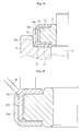
- an adhesive is injected from a nozzle 40 into the fitting part of the first outer member 20a and the second outer member 20b.
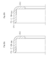
- the end surface of the cylindrical portion 20a1 of the first outer member 20a is positioned to be lower than an outside surface of the radial portion 20b2 of the second outer member 20b, and is provided with the chamfered portion 28, which facilitates injection of the adhesive.
- the adhesive is cured through baking. When the adhesive is anaerobic, it is unnecessary to perform baking.
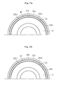
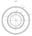
- FIGS. 17 are each a horizontal sectional view of a structure in which the first outer member 20a and the second outer member 20b are fitted to and temporarily fixed to each other.
- a plurality of protruding portions 21a are provided on the inner peripheral surface 21 of the cylindrical portion 20a1 of the first outer member 20a .
- Those protruding portions 21a are press-fitted to an outer peripheral surface 40 of the cylindrical portion 20b1 of the second outer member 20b. With this, press-fitting can be performed without deterioration of accuracies of the first outer member 20a and the second outer member 20b.
- an epoxy or anaerobic adhesive is continuously injected.
- the dynamic pressure generating grooves 11a, 12a, 13a, 22a, and 23a are each formed in a herringbone pattern. Instead, there may be employed appropriate dynamic pressure generating grooves formed in a spiral pattern, a stepped pattern, a circular-arc pattern, or the like.
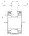
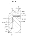
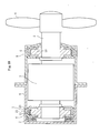
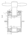
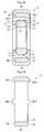
- FIG. 18 is an axial sectional view of a bearing unit 1 incorporating a fluid dynamic bearing device according to a first embodiment of the second invention of the present application.
- the bearing unit 1 is used, for example, by being incorporated into a motor for a small exhaust fan for a 24-hour ventilation system to be installed in a dwelling room of a house (more strictly speaking, inner-rotor motor for an exhaust fan).
- the projecting portion 10a has a herringbone pattern in which the dynamic pressure generating grooves 11a formed all over the outer peripheral surface 11 and each bent into a V-shape and hill portions 11b (indicated by cross-hatching in FIG. 20(b) ) defining the dynamic pressure generating grooves 11a are arranged alternately with each other in a circumferential direction.
- the dynamic pressure generating grooves 11a are formed, for example, by a rolling process.
- the projecting portion 10a of the inner member 10 is made of a sintered metal, and hence plastic flow of the outer peripheral surface 11 of the projecting portion 10a, which is generated by compression along with the rolling process, can be absorbed by inner pores of the sintered metal.
- swelling of a surface of the projecting portion 10a, which is caused by the plastic flow is suppressed, and hence the dynamic pressure generating grooves 11a and the hill portions 11b can be formed with high accuracy.
- Both the side surfaces 12 and 13 of the projecting portion 10a of the inner member 10 are each formed of a radial flat surface orthogonal to the axial line H, and are held in contact with the lubricating oil filling the thrust bearing gaps T.
- Dynamic pressure generating grooves 12a and 13a are formed respectively in both the side surfaces 12 and 13 of the projecting portion 10a.
- FIGS. 20(a) and 20(c) illustrates the side surface 12 on a left side of the projecting portion 10a
- FIG. 20 (c) illustrates the side surface 13 on a right side of the projecting portion 10a.
- the projecting portion 10a has a herringbone pattern in which the dynamic pressure generating grooves 12a and 13a respectively formed all over both the side surfaces 12 and 13 and each bent into a V-shape and hill portions 12b and 13b (indicated by cross-hatching in FIGS. 20(a) and 20(c) ) respectively defining the dynamic pressure generating grooves 12a and 13a are arranged alternately with each other in the circumferential direction.
- the projecting portion 10a of the inner member 10 is made of a sintered metal, and hence the dynamic pressure generating grooves 12a and 13a of both the side surfaces 12 and 13 can be formed by a pressing process with high accuracy. Further, simultaneously with sizing of the projecting portion 10a, the dynamic pressure generating grooves 12a and 13a can be formed by molding.
- the sleeve portion 10b is formed to be longer than a width between both the side surfaces 12 and 13 of the projecting portion 10a, and projects in the axial direction with respect to both the side surfaces 12 and 13.
- the inner member 10 is fixed to the rotary shaft 2, for example, by press-fitting (lightly press-fitting) the inner peripheral surface 10c to the outer peripheral surface of the rotary shaft 2, or by interposing an adhesive between the inner peripheral surface 10c and the outer peripheral surface of the rotary shaft 2.
- a right end surface 43 of the sleeve portion 10b is provided with identification grooves 44.
- this end portion of the sleeve portion 10b which is provided with the identification grooves 44, is arranged on the right side as illustrated in FIG. 19 .
- the identification indicators of those two types that is, the outer diameter dimensions A and B and the identification grooves 44 are provided to the sleeve portion 10b, but only one of those two types may be provided.
- the rotational direction when the identification indicator is arranged on the right side, the rotational direction is set to the rightward direction. Reversely, the rotational direction may be set to the leftward direction (counterclockwise direction).
- a shape of each of the identification grooves 44 is not limited to the above-mentioned one.
- identification grooves each having an arrow shape directly indicating the rotational direction may be provided.
- the dimension A of the outer peripheral surface 42 of the end portion of the sleeve portion 10b of the inner member 10 is set to be larger.
- the outer peripheral surface 42 of the end portion is also formed by a powder molding step or a sizing step.
- the indicators for identifying the rotational direction are not limited to the above-mentioned ones.
- an indicator indicating the rotational direction may be provided on an outer surface of the outer member 20, or the outside outer member 20a and the inside outer member 20b may be formed to have surfaces different from each other in hue. In order to form the surfaces different from each other in hue, materials different from each other in hue are used, or surface treatment is performed.
- a copper-iron based material is used as a material for a sintered metal of the projecting portion 10a as the part forming the bearing surface of the inner member 10, and a formulation ratio of copper is set to range from 20% to 80%.
- a formulation ratio of copper is set to range from 20% to 80%.
- the formulation ratio of the copper is less than 20%, there arise problems with formability of the dynamic pressure generating grooves and lubricity therein. Meanwhile, when the formulation ratio of the copper exceeds 80%, it is difficult to secure abrasion resistance.
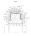
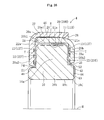
- a small-diameter inner peripheral surface 24 at the inner-diameter-side end portion of the radial portion 20a2 of the outside outer member 20a and a small-diameter inner peripheral surface 25 at the inner-diameter-side end portion of the inside outer member 20b are each formed into a shape of a tapered surface increasing in diameter toward the outside. Sealed spaces S1 and S2 are formed between the small-diameter inner peripheral surfaces 24 and 25 and the end-portion outer peripheral surfaces 41 and 42 of the sleeve portion 10b of the inner member 10. With this, leakage of the lubricating oil to the outside is more effectively prevented.
- the fitting length between the inner peripheral surface 21 of the cylindrical portion 20a1 and the outer peripheral surface 27 of the cylindrical portion 20b1 is large, and hence stable assembly and fixation by bonding can be achieved.
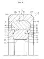
- the lubricating oil is filled into an interior space of the fluid dynamic bearing device 4 structured as described above, including the inner pores of the inner member 10 made of a sintered metal. As illustrated in FIG. 19 , the lubricating oil fills the radial bearing gap R, the thrust bearing gaps T, and the sealed spaces S1 and S2. A capillary force of the thrust bearing gaps T causes the lubricating oil to be drawn into an outer diameter side (radial bearing gap R side). An oil level of the lubricating oil is maintained in each of the sealed spaces S1 and S2. Note that, the capillary force of the thrust bearing gaps T causes the lubricating oil to be drawn into the outer diameter side (radial bearing gap R side), and hence the fluid dynamic bearing device 4 may be designed without being provided with the sealed spaces S1 and S2.
- an oil films are formed respectively in the thrust bearing gaps T between both the side surfaces 12 and 13 of the inner member 10 and the inside surfaces 22 and 23 of the outer member 20 respectively facing both the side surfaces 12 and 13.
- pressure of the oil films in the thrust bearing gaps T is increased by the dynamic pressure generating grooves 12a and 13a.
- the rotary shaft 2 and the inner member 10 are supported in a non-contact manner in both thrust directions with respect to the outer member 20 mounted to the static-side member.
- the radial bearing gap R and the thrust bearing gaps T in the illustration are exaggerated in size.
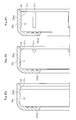
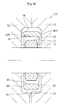
- a projection portion 21a in this embodiment is provided at an opening end portion of the inner peripheral surface 21 of the cylindrical portion 20a1 of the outside outer member 20a.
- FIGS. 27 illustrate a form of the projection portion 21a.
- the projection portion 21a illustrated in FIG. 27 (a) is formed as an annular circumferential projection along the opening end portion of the inner peripheral surface 21 of the cylindrical portion 20a1 of the outside outer member 20a. This projection portion 21a is continuous with the chamfered portion 28.
- the projection portion 21a illustrated in FIG. 27 (b) comprises projection portions 21a provided at eight points in the circumferential direction at the opening end portion of the inner peripheral surface 21 of the cylindrical portion 20a1 of the outside outer member 20a.
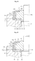
- the radial portion 20a2 of the outside outer member 20a is directed downward and inserted along the guide surface 34 of the fixing jig F so that the outside surface of the radial portion 20a2 is held in abutment against the placing surface 30. In this way, the outside outer member 20a is set. Then, after the inner peripheral surface 10c of the sleeve portion 10b of the inner member 10 is fitted to the guide surface 37 of the moving jig G, the inner member 10 is inserted into the outside outer member 20a so that the side surface 12 thereof is brought into abutment against the inside surface 22 of the outside outer member 20a. In this state, an appropriate load is applied downward to the inner member 10.
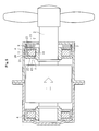
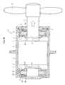
- FIG. 34 is an axial sectional view of a bearing unit 1 incorporating a fluid dynamic bearing device according to an embodiment of the third invention of the present application.
- the bearing unit 1 is used, for example, by being incorporated into a motor for a small exhaust fan for a 24-hour ventilation system to be installed in a dwelling room of a house (more strictly speaking, inner-rotor motor for an exhaust fan) .
- the inner member 10 is obtained, for example, by forming a metal into a ring shape.
- the inner member 10 is made of a sintered metal.
- An outer peripheral surface 11 of the inner member 10 is formed into a shape of a cylindrical surface, and is held in contact with the lubricating oil filling the radial bearing gap R (refer to FIG. 36 ).
- a radial dynamic pressure generating portion is formed on the outer peripheral surface 11 of the inner member 10.
- the radial dynamic pressure generating portion in this embodiment has a herringbone pattern in which dynamic pressure generating grooves Ba formed all over the outer peripheral surface 11 and each bent into a V-shape and hill portions Bb (indicated by cross-hatching in FIG.
- the dynamic pressure generating grooves Ba are arrayed alternately with each other in the circumferential direction.
- the dynamic pressure generating grooves Ba are formed, for example, by a rolling process.
- the innermember 10 is made of a sintered metal, and hence plastic flow of the outer peripheral surface 11 of the inner member 10, which is generated by compression along with the rolling process, can be absorbed by inner pores of the sintered metal.
- swelling of the surface of the inner member 10, which is caused by the plastic flow is suppressed, and hence the radial dynamic pressure generating portion (dynamic pressure generating grooves Ba and hill portions Bb) can be formed with high accuracy.
- End surfaces 13 and 13 on both the axial sides of the inner member 10 each have a shape symmetrical with each other with respect to an axial center plane of the inner member 10.
- the end surface 13 is formed of a tapered surface 13a provided on the outer diameter side and a flat surface 13b provided on the inner diameter side.
- the tapered surface 13a is provided while being inclined toward the outer diameter side and an axial central portion side (that is, side on which the end surfaces 13 and 13 come close to each other).
- the flat surface 13b extends from an inner diameter end of the tapered surface 13a toward the inner diameter side.
- the tapered surface 13a and the flat surface 13b are held in contact with the lubricating oil in the thrust bearing gaps T.
- the tapered surface 13a and the flat surface 13b are each formed of an even and smooth surface.
- the outer member 20 has a shape of a ring arranged on the outer diameter side with respect to the inner member 10, and comprises a core metal M and a resin molded portion N formed by injection molding with use of the core metal M as an insert component.
- the core metal M is obtained, for example, by forming a metal into a ring shape.
- the core metal M is made of a sinteredmetal. As illustrated in FIG. 35 , all of an outer peripheral surface M1 and both axial end surfaces M2 and M2 of the core metal M, and both axial end portions of an inner peripheral surface M3 are held in an adhering manner by the resin molded portion N.
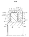
- the outer member 20 has a substantially C-shape opened to the inner diameter side in axial cross-section, and has a large-diameter inner peripheral surface 21, a pair of small-diameter inner peripheral surfaces 22 and 22 respectively provided on both axial sides of the large-diameter inner peripheral surface 21, and a pair of shoulder surfaces 23 and 23 formed between both axial end portions of the large-diameter inner peripheral surface 21 and the small-diameter inner peripheral surfaces 22 and 22.
- the large-diameter inner peripheral surface 21 is formed into a shape of a smooth cylindrical surface, and in this embodiment, is formed of the inner peripheral surface M3 of the core metal M.
- the large-diameter inner peripheral surface 21 faces the outer peripheral surface 11 of the inner member 10 across the radial bearing gap R (refer to FIG. 36 ).
- An axial dimension of the core metal M is larger than an axial dimension of the inner member 10.
- both the axial end surfaces M2 and M2 of the core metal M are positioned on an axially outer side with respect to the flat surfaces 13b and 13b of the end surfaces 13 and 13 of the inner member 10 and the flat surfaces 23b (described in detail below) of the shoulder surfaces 23 and 23 of the outer member 20, which face the flat surfaces 13b and 13b in the axial direction.
- parts of the resin molded portion N project to the axial center side with respect to both the axial end surfaces M2 and M2 of the core metal M.
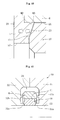
- the lubricating oil is filled into an interior space of the fluid dynamic bearing device 4 structured as described above, including the inner pores of the inner member 10 and the core metal M made of a sinteredmetal. As illustrated in FIG. 36 , the lubricating oil fills the entire radial bearing gap R and the thrust bearing gaps T up to vicinities of inner diameter ends thereof. A capillary force of the thrust bearing gaps T causes the lubricating oil to be drawn into an outer diameter side (radial bearing gap R side). An oil level of the lubricating oil is maintained in each of the thrust bearing gaps T. It is preferred that the oil level of the lubricating oil be maintained at the cylindrical portion of the thrust bearing gaps T (gap between the flat surfaces 13b and 23b).
- the spring 7 applies an axial preload to both the fluid dynamic bearing devices 4 and 4.
- the elastic force of the spring 7 is set within such a range that the outer member 20 is prevented from being rotated and the outer member 20 and the inner member 10 are prevented from coming into sliding contact with each other.
- the elastic force of the spring 7 be set approximately to range from 20% to 80% of a load capacity of the pressure generated in the thrust bearing gaps T.
- the inner member 10 is provided in the axial direction between the shoulder surfaces 23 and 23 of the outer member 20.
- the inner member 10 is prevented from dropping off from an inner periphery of the outer member 20.
- the inner member 10 and the outer member 20 are prevented from being separated from each other, and hence the fluid dynamic bearing device 4 can be integrally treated.
- the fluid dynamic bearing device 4 is more easily mounted to the rotary shaft 2 and the housing 5.
- a sealed space having a wedge-like shape in cross-section may be provided by forming any one of the flat surface 13b of the end surface 13 of the inner member 10 and the flat surface 23b of the shoulder surface 23 of the outer member 20 into a shape of a tapered surface.
- the radial gap is set to range from 10 ⁇ m to 50 ⁇ m, preferably, to range from 20 ⁇ m to 40 ⁇ m.
- the inner member 10 and the core metal M are each made of a sintered metal excellent in formability, and hence the inner member 10 and the core metal M can be molded with high dimensional accuracy. Therefore, the gap to be formed therebetween also can be set with high accuracy, and hence can be set to fall within the minute ranges as described above.
- the resin molded portion N of the outer member 20 undergoes molding shrinkage.
- molding shrinkage of a resin molded product occurs toward a central portion in a thickness direction.
- the shoulder surfaces 23 of the outer member 20 may be pressed against the end surfaces 13 of the inner member 10.
- the core metal M is arranged as an insert component in the outer member 20.
- the core metal M is larger in axial dimension than at least parts of the inner member 10, which are arranged in the cavity 34, and is provided to protrude to both the axial sides of the inner member 10.
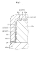
- This core metal M prevents the shrinkage of the resin molded portion N to the axial center side. That is, as illustrated in FIG. 40 , molding shrinkage in the axial direction of the shoulder surface 23 of the outer member 20 occurs with an axial position of corresponding one of both the axial end surfaces M2 of the core metal M (position indicated by a dotted line) as a reference, and in this region, the resin of the resin molded portion N shrinks from both the axial sides toward the reference position (dotted line position). As a result, the shoulder surface 23 of the outer member 20, which has remained adhering to the end surface 13 of the inner member 10, shrinks in a direction of separating from the inner member 10, with the result of retracting to a position indicated by a chain line in FIG. 40 .
- the oil level is retracted to the bearing interior side (outer diameter side), and is maintained in the cylindrical portion of the thrust bearing gaps T (gap between the flat surfaces 13b and 23b). With this, the lubricating oil does not overflow from the thrust bearing gaps T due to thermal expansion within an expected temperature range. In this way, the fluid dynamic bearing device 4 is completed.
- the present invention is not limited to the above-mentioned embodiment.
- description is made of other embodiments of the third invention of the present application.
- parts having the same functions as those in the above-mentioned embodiment are denoted by the same reference symbols, and redundant description thereof is omitted.
- the fixed die 31 and the movable die 32 are respectively provided with projecting portions 31b and 32b to abut against an end surface of the core metal M arranged in the cavity 34 from both the axial sides.
- the projecting portions 31b and 32b are arranged, for example, at an equal interval at a plurality of points spaced apart from each other in the circumferential direction.
- the projecting portions 31b and 32b enable the core metal M to be reliably positioned in the axial direction in the cavity 34.
- axial holes are formed by the projecting portions 31b and 32b to extend from the end surface of the outer member 20 to the core metal M (not shown). After the inner member 10 and the outer member 20 are taken out from the die set 30, the axial holes are closed by an adhesive, a resin, or the like.
- the large-diameter inner peripheral surface 21 of the outer member 20 is formed of the inner peripheral surface M3 of the core metal M, and the radial bearing gap R is formed between the core metal M and the inner member 10.
- the present invention is not limited thereto.
- the large-diameter inner peripheral surface 21 of the outer member 20 may be formed of the resin molded portion N.
- the outer peripheral surface 11 of the inner member 10 and the core metal M are spaced apart from each other in the radial direction, and the resin molded portion N is provided in this radial gap.
- the radial bearing gap R is formed between the large-diameter inner peripheral surface 21 formed of the resin molded portion N of the outer member 20 and the outer peripheral surface 11 of the inner member 10.
- the thrust bearing gaps T are formed between the pair of shoulder surfaces 23 and 23 formed of the resin molded portion N of the outer member 20 and both the axial end surfaces 13 and 13 of the inner member 10.
- the core metal M in this embodiment has a ring shape as illustrated in FIGS. 43 and 44 , and comprises projecting portions M20 projecting from end surfaces on both sides in the axial direction.
- the projecting portions M20 are provided at an equal interval at a plurality of points spaced apart from each together in the circumferential direction (for example, at four points, refer to FIG. 44 ). Both the axial end surfaces of each of the projecting portions M20 are exposed to be flush with both the axial end surfaces of the outer member 20 (refer to FIG. 42 ).
- FIG. 45 illustrates a state in which the core metal M illustrated in FIGS. 43 and 44 is arranged in the cavity 34 of the die set 30. At this time, the projecting portions M20 and M20 projecting from both the axial end surfaces M2 and M2 of the core metal M are sandwiched by the fixed die 31 and the movable die 32 from both the axial sides. In this way, the core metal M is positioned in the cavity 34. In this state, a molten resin is injected from the gate 35 so that the molten resin is filled in the cavity 34.
- molding shrinkage of the resin molded portion N occurs in the axial direction with both the axial end surfaces M2 and M2 of the core metal M as references.
- the shoulder surfaces 23 and 23 of the outer member 20, which are formed of the resin molded portion N separate from both the axial end surfaces 13 and 13 of the inner member 10.
- the resin molded portion N of the outer member 20 separates from the inner member 10, and gaps formed by the separating function as the radial bearing gap R and the thrust bearing gaps T.
- the thrust dynamic pressure generating portion when the thrust dynamic pressure generating portion is formed of dynamic pressure generating grooves of a pump-out type, which push the lubricating oil in the thrust bearing gaps T into the outer diameter side (radial bearing gap R side), the lubricating oil can be drawn into the radial bearing gap R side. As a result, oil leakage is more reliably prevented.
- the thrust dynamic pressure generating portion is provided to the inner member 10 made of a sintered metal, simultaneously with sizing of the inner member 10, the thrust dynamic pressure generating portion can be formed by molding. Meanwhile, when the thrust dynamic pressure generating portion is provided to the resin molded portion N of the outer member 20, simultaneously with injection molding of the outer member 20, the thrust dynamic pressure generating portion can be formed by molding.
- a cylindrical bearing may be formed by forming each of the outer peripheral surface 11 of the inner member 10 and the large-diameter inner peripheral surface 21 of the outer member 20, which face each other across the radial bearing gap R, into a shape of a cylindrical surface.
- none of the outer peripheral surface 11 and the large-diameter inner peripheral surface 21 is provided with the radial dynamic pressure generating portion.
- the lubricating oil in the radial bearing gap R is fluidized, and hence a dynamic pressure action is generated.
Landscapes
- Engineering & Computer Science (AREA)
- General Engineering & Computer Science (AREA)
- Mechanical Engineering (AREA)
- Physics & Mathematics (AREA)
- Fluid Mechanics (AREA)
- Power Engineering (AREA)
- Chemical & Material Sciences (AREA)
- Oil, Petroleum & Natural Gas (AREA)
- Metallurgy (AREA)
- Sliding-Contact Bearings (AREA)
- Mounting Of Bearings Or Others (AREA)
Applications Claiming Priority (4)
| Application Number | Priority Date | Filing Date | Title |
|---|---|---|---|
| JP2010074454A JP2011208670A (ja) | 2010-03-29 | 2010-03-29 | 流体動圧軸受装置及びその製造方法 |
| JP2010103394A JP5528897B2 (ja) | 2010-04-28 | 2010-04-28 | 流体動圧軸受装置およびその組み立て方法 |
| JP2010186055A JP2012042035A (ja) | 2010-08-23 | 2010-08-23 | 流体動圧軸受装置およびその組立方法 |
| PCT/JP2011/057631 WO2011122556A1 (ja) | 2010-03-29 | 2011-03-28 | 流体動圧軸受装置およびその組立方法 |
Publications (3)
| Publication Number | Publication Date |
|---|---|
| EP2554859A1 true EP2554859A1 (de) | 2013-02-06 |
| EP2554859A4 EP2554859A4 (de) | 2014-03-19 |
| EP2554859B1 EP2554859B1 (de) | 2017-03-22 |
Family
ID=44712252
Family Applications (1)
| Application Number | Title | Priority Date | Filing Date |
|---|---|---|---|
| EP11762780.2A Not-in-force EP2554859B1 (de) | 2010-03-29 | 2011-03-28 | Fluiddynamische lagerungseinheit und montageverfahren dafür |
Country Status (4)
| Country | Link |
|---|---|
| US (1) | US9154012B2 (de) |
| EP (1) | EP2554859B1 (de) |
| CN (1) | CN102844576B (de) |
| WO (1) | WO2011122556A1 (de) |
Families Citing this family (12)
| Publication number | Priority date | Publication date | Assignee | Title |
|---|---|---|---|---|
| JP5335621B2 (ja) * | 2009-08-28 | 2013-11-06 | Ntn株式会社 | すべり軸受およびこれを備えるすべり軸受ユニット、並びにこの軸受ユニットを備えるモータ |
| JP6100046B2 (ja) * | 2013-03-19 | 2017-03-22 | Ntn株式会社 | 流体動圧軸受装置およびこれを備えるモータ |
| JP6189065B2 (ja) * | 2013-03-25 | 2017-08-30 | Ntn株式会社 | 流体動圧軸受装置およびその組立方法 |
| US10424988B2 (en) * | 2013-04-05 | 2019-09-24 | General Electric Company | Downhole electric submersible pumps with high rotordynamic stability margin |
| EP2803874B1 (de) * | 2013-05-13 | 2019-08-14 | Aktiebolaget SKF | Landungslager und magnetische Lageranordnung |
| EP2803875B1 (de) * | 2013-05-13 | 2019-03-13 | Aktiebolaget SKF | Landungslager und magnetische Lageranordnung |
| JP6502068B2 (ja) * | 2014-11-20 | 2019-04-17 | Ntn株式会社 | 流体動圧軸受装置の製造方法 |
| EP3104031B1 (de) * | 2015-06-10 | 2019-08-07 | MAHLE International GmbH | Gleitelement mit einem flexiblen klebstoff |
| DE102018220462A1 (de) * | 2018-11-28 | 2020-05-28 | Hanon Systems Efp Deutschland Gmbh | Elektrisch angetriebene Maschine, insbesondere Pumpe |
| TWI715450B (zh) * | 2020-02-25 | 2021-01-01 | 建準電機工業股份有限公司 | 軸承系統及其止推板 |
| CN112128246B (zh) * | 2020-09-22 | 2022-08-12 | 东南大学 | 一种轴向小孔常压供水动静压螺旋槽推力轴承 |
| US12247617B2 (en) | 2022-12-08 | 2025-03-11 | Hamilton Sundstrand Corporation | Cavitation resistant journal bearing |
Family Cites Families (26)
| Publication number | Priority date | Publication date | Assignee | Title |
|---|---|---|---|---|
| US5941646A (en) | 1996-12-25 | 1999-08-24 | Ntn Corporation | Hydrodynamic type porous oil-impregnated bearing and bearing device |
| JP2004353871A (ja) | 1996-12-25 | 2004-12-16 | Ntn Corp | 動圧型多孔質含油軸受 |
| JPH10311331A (ja) | 1997-05-09 | 1998-11-24 | Matsushita Seiko Co Ltd | スラスト軸受 |
| JP2000249142A (ja) | 1999-03-03 | 2000-09-12 | Nsk Ltd | 転がり軸受 |
| JP2001132738A (ja) | 1999-11-02 | 2001-05-18 | Seiko Instruments Inc | フランジ付シャフトの組立方法、及び流体動圧軸受 |
| US6536983B1 (en) * | 2000-01-20 | 2003-03-25 | Engineered Controls International Inc. | Crimp joint for pressure containing gas and fluid distribution devices |
| DE10024953A1 (de) * | 2000-05-22 | 2001-11-29 | Richter Chemie Tech Itt Gmbh | Kreiselpumpe mit Magnetkupplung |
| US7048444B2 (en) | 2001-11-13 | 2006-05-23 | Ntn Corporation | Fluid lubricated bearing device |
| US20070230843A1 (en) | 2006-01-06 | 2007-10-04 | Tetsuya Kurimura | Fluid lubricated bearing device |
| JP4541351B2 (ja) | 2001-11-13 | 2010-09-08 | Ntn株式会社 | 流体軸受装置 |
| US7296931B2 (en) | 2002-11-13 | 2007-11-20 | Ntn Corporation | Fluid lubricated bearing device |
| JP3991215B2 (ja) | 2002-09-20 | 2007-10-17 | 株式会社ジェイテクト | 動圧軸受装置 |
| US20040120619A1 (en) * | 2002-12-18 | 2004-06-24 | Dong-Yeh Chai | Independent rotational supportive pad with use of flat bearing ring plate for CRT/TFT-LCD/PDP television monitor, computer monitor, stereo speaker, laptop computers and dinner dishes |
| JP3686665B2 (ja) * | 2004-07-28 | 2005-08-24 | Ntn株式会社 | 動圧型軸受ユニット及びその製造方法 |
| JP4954478B2 (ja) * | 2005-01-05 | 2012-06-13 | Ntn株式会社 | 流体軸受装置 |
| US20090142010A1 (en) | 2005-01-05 | 2009-06-04 | Ntn Corporation | Sintered metal material, sintered oil-impregnated bearing formed of the metal material, and fluid lubrication bearing device |
| JP2007024089A (ja) | 2005-07-12 | 2007-02-01 | Ntn Corp | 動圧軸受装置およびモータ |
| JP2007051717A (ja) | 2005-08-18 | 2007-03-01 | Ntn Corp | 動圧軸受装置の製造方法 |
| JP2008190711A (ja) | 2006-07-21 | 2008-08-21 | Ntn Corp | 動圧軸受装置の製造方法 |
| JP2006342975A (ja) * | 2006-09-25 | 2006-12-21 | Ntn Corp | 動圧型軸受装置 |
| JP5207657B2 (ja) * | 2007-04-23 | 2013-06-12 | Ntn株式会社 | 動圧軸受装置の製造方法 |
| DE102007019642B4 (de) | 2007-04-26 | 2014-09-04 | Minebea Co., Ltd. | Fluiddynamisches Lagersystem |
| JP2008298235A (ja) | 2007-06-01 | 2008-12-11 | Ntn Corp | 流体軸受装置及びその組み立て方法 |
| JP2009008160A (ja) | 2007-06-28 | 2009-01-15 | Nippon Densan Corp | 流体動圧軸受機構、流体動圧軸受機構の製造方法およびモータ |
| US8591113B2 (en) * | 2008-07-08 | 2013-11-26 | Ntn Corporation | Fluid dynamic bearing device |
| JP5335621B2 (ja) * | 2009-08-28 | 2013-11-06 | Ntn株式会社 | すべり軸受およびこれを備えるすべり軸受ユニット、並びにこの軸受ユニットを備えるモータ |
-
2011
- 2011-03-28 WO PCT/JP2011/057631 patent/WO2011122556A1/ja not_active Ceased
- 2011-03-28 EP EP11762780.2A patent/EP2554859B1/de not_active Not-in-force
- 2011-03-28 CN CN201180016768.2A patent/CN102844576B/zh not_active Expired - Fee Related
- 2011-03-28 US US13/580,091 patent/US9154012B2/en not_active Expired - Fee Related
Non-Patent Citations (2)
| Title |
|---|
| No further relevant documents disclosed * |
| See also references of WO2011122556A1 * |
Also Published As
| Publication number | Publication date |
|---|---|
| US20120315169A1 (en) | 2012-12-13 |
| EP2554859A4 (de) | 2014-03-19 |
| CN102844576A (zh) | 2012-12-26 |
| EP2554859B1 (de) | 2017-03-22 |
| CN102844576B (zh) | 2015-12-02 |
| WO2011122556A1 (ja) | 2011-10-06 |
| US9154012B2 (en) | 2015-10-06 |
Similar Documents
| Publication | Publication Date | Title |
|---|---|---|
| EP2554859B1 (de) | Fluiddynamische lagerungseinheit und montageverfahren dafür | |
| US9127710B2 (en) | Slide bearing, slide bearing unit with same, and motor with the bearing unit | |
| CN101305193B (zh) | 树脂制保持器和滚动轴承 | |
| US3302048A (en) | Self-aligning gas bearing | |
| US20090080824A1 (en) | Bearing having thermal compensating capability | |
| JP2012505361A5 (de) | ||
| EP2899417B1 (de) | Hydrodynamische lagervorrichtung und motor damit | |
| JP2002369474A (ja) | インペラ軸支持用転がり軸受装置 | |
| US20070183699A1 (en) | Bearing unit and motor using the bearing unit | |
| JP5528897B2 (ja) | 流体動圧軸受装置およびその組み立て方法 | |
| CN107949710B (zh) | 推力滚子轴承和轴承装置 | |
| JP2012042035A (ja) | 流体動圧軸受装置およびその組立方法 | |
| JP2011127713A (ja) | 玉軸受用保持器およびこれを備える玉軸受 | |
| JP2010169140A (ja) | スラストころ軸受 | |
| US20120062079A1 (en) | Rotor for Motor | |
| JP6087066B2 (ja) | 流体動圧軸受装置、及び、流体動圧軸受装置の製造方法 | |
| JP5832849B2 (ja) | 流体動圧軸受装置およびその製造方法 | |
| CN113819144B (zh) | 一种轴承保持架、滚动球轴承及电机 | |
| US7735227B2 (en) | Method for providing a lubricating layer to a bearing | |
| JP2011208670A (ja) | 流体動圧軸受装置及びその製造方法 | |
| JP6668098B2 (ja) | 流体動圧軸受装置 | |
| JP6189065B2 (ja) | 流体動圧軸受装置およびその組立方法 | |
| CN220488096U (zh) | 一种轴承组件 | |
| JP6261922B2 (ja) | 流体動圧軸受装置及び内方部材の製造方法 | |
| JP2012072816A (ja) | 流体動圧軸受装置およびその組立方法 |
Legal Events
| Date | Code | Title | Description |
|---|---|---|---|
| PUAI | Public reference made under article 153(3) epc to a published international application that has entered the european phase |
Free format text: ORIGINAL CODE: 0009012 |
|
| 17P | Request for examination filed |
Effective date: 20120914 |
|
| AK | Designated contracting states |
Kind code of ref document: A1 Designated state(s): AL AT BE BG CH CY CZ DE DK EE ES FI FR GB GR HR HU IE IS IT LI LT LU LV MC MK MT NL NO PL PT RO RS SE SI SK SM TR |
|
| DAX | Request for extension of the european patent (deleted) | ||
| A4 | Supplementary search report drawn up and despatched |
Effective date: 20140218 |
|
| RIC1 | Information provided on ipc code assigned before grant |
Ipc: F16C 17/10 20060101AFI20140212BHEP Ipc: F16C 33/14 20060101ALI20140212BHEP Ipc: H02K 5/167 20060101ALI20140212BHEP Ipc: F16C 43/02 20060101ALI20140212BHEP Ipc: F16C 33/12 20060101ALI20140212BHEP Ipc: F16C 33/10 20060101ALI20140212BHEP Ipc: H02K 7/08 20060101ALI20140212BHEP |
|
| 17Q | First examination report despatched |
Effective date: 20160222 |
|
| GRAP | Despatch of communication of intention to grant a patent |
Free format text: ORIGINAL CODE: EPIDOSNIGR1 |
|
| INTG | Intention to grant announced |
Effective date: 20161005 |
|
| GRAS | Grant fee paid |
Free format text: ORIGINAL CODE: EPIDOSNIGR3 |
|
| GRAA | (expected) grant |
Free format text: ORIGINAL CODE: 0009210 |
|
| AK | Designated contracting states |
Kind code of ref document: B1 Designated state(s): AL AT BE BG CH CY CZ DE DK EE ES FI FR GB GR HR HU IE IS IT LI LT LU LV MC MK MT NL NO PL PT RO RS SE SI SK SM TR |
|
| REG | Reference to a national code |
Ref country code: GB Ref legal event code: FG4D |
|
| RIN1 | Information on inventor provided before grant (corrected) |
Inventor name: MORI NATSUHIKO Inventor name: HORI MASAHARU Inventor name: SATOJI FUMINORI Inventor name: HIRADE JUN Inventor name: KURIMURA TETSUYA Inventor name: BITO KIMIHIKO Inventor name: NIWA TOSHIAKI Inventor name: YAMAMOTO YASUHIRO Inventor name: HAYASHI TATSUYA |
|
| REG | Reference to a national code |
Ref country code: CH Ref legal event code: EP |
|
| REG | Reference to a national code |
Ref country code: AT Ref legal event code: REF Ref document number: 878097 Country of ref document: AT Kind code of ref document: T Effective date: 20170415 |
|
| REG | Reference to a national code |
Ref country code: IE Ref legal event code: FG4D |
|
| REG | Reference to a national code |
Ref country code: FR Ref legal event code: PLFP Year of fee payment: 7 |
|
| REG | Reference to a national code |
Ref country code: DE Ref legal event code: R096 Ref document number: 602011036248 Country of ref document: DE |
|
| REG | Reference to a national code |
Ref country code: NL Ref legal event code: MP Effective date: 20170322 |
|
| PG25 | Lapsed in a contracting state [announced via postgrant information from national office to epo] |
Ref country code: NO Free format text: LAPSE BECAUSE OF FAILURE TO SUBMIT A TRANSLATION OF THE DESCRIPTION OR TO PAY THE FEE WITHIN THE PRESCRIBED TIME-LIMIT Effective date: 20170622 Ref country code: HR Free format text: LAPSE BECAUSE OF FAILURE TO SUBMIT A TRANSLATION OF THE DESCRIPTION OR TO PAY THE FEE WITHIN THE PRESCRIBED TIME-LIMIT Effective date: 20170322 Ref country code: FI Free format text: LAPSE BECAUSE OF FAILURE TO SUBMIT A TRANSLATION OF THE DESCRIPTION OR TO PAY THE FEE WITHIN THE PRESCRIBED TIME-LIMIT Effective date: 20170322 Ref country code: LT Free format text: LAPSE BECAUSE OF FAILURE TO SUBMIT A TRANSLATION OF THE DESCRIPTION OR TO PAY THE FEE WITHIN THE PRESCRIBED TIME-LIMIT Effective date: 20170322 Ref country code: GR Free format text: LAPSE BECAUSE OF FAILURE TO SUBMIT A TRANSLATION OF THE DESCRIPTION OR TO PAY THE FEE WITHIN THE PRESCRIBED TIME-LIMIT Effective date: 20170623 |
|
| REG | Reference to a national code |
Ref country code: LT Ref legal event code: MG4D |
|
| REG | Reference to a national code |
Ref country code: AT Ref legal event code: MK05 Ref document number: 878097 Country of ref document: AT Kind code of ref document: T Effective date: 20170322 |
|
| PG25 | Lapsed in a contracting state [announced via postgrant information from national office to epo] |
Ref country code: BG Free format text: LAPSE BECAUSE OF FAILURE TO SUBMIT A TRANSLATION OF THE DESCRIPTION OR TO PAY THE FEE WITHIN THE PRESCRIBED TIME-LIMIT Effective date: 20170622 Ref country code: RS Free format text: LAPSE BECAUSE OF FAILURE TO SUBMIT A TRANSLATION OF THE DESCRIPTION OR TO PAY THE FEE WITHIN THE PRESCRIBED TIME-LIMIT Effective date: 20170322 Ref country code: SE Free format text: LAPSE BECAUSE OF FAILURE TO SUBMIT A TRANSLATION OF THE DESCRIPTION OR TO PAY THE FEE WITHIN THE PRESCRIBED TIME-LIMIT Effective date: 20170322 Ref country code: LV Free format text: LAPSE BECAUSE OF FAILURE TO SUBMIT A TRANSLATION OF THE DESCRIPTION OR TO PAY THE FEE WITHIN THE PRESCRIBED TIME-LIMIT Effective date: 20170322 |
|
| PG25 | Lapsed in a contracting state [announced via postgrant information from national office to epo] |
Ref country code: NL Free format text: LAPSE BECAUSE OF FAILURE TO SUBMIT A TRANSLATION OF THE DESCRIPTION OR TO PAY THE FEE WITHIN THE PRESCRIBED TIME-LIMIT Effective date: 20170322 |
|
| PG25 | Lapsed in a contracting state [announced via postgrant information from national office to epo] |
Ref country code: ES Free format text: LAPSE BECAUSE OF FAILURE TO SUBMIT A TRANSLATION OF THE DESCRIPTION OR TO PAY THE FEE WITHIN THE PRESCRIBED TIME-LIMIT Effective date: 20170322 Ref country code: IT Free format text: LAPSE BECAUSE OF FAILURE TO SUBMIT A TRANSLATION OF THE DESCRIPTION OR TO PAY THE FEE WITHIN THE PRESCRIBED TIME-LIMIT Effective date: 20170322 Ref country code: EE Free format text: LAPSE BECAUSE OF FAILURE TO SUBMIT A TRANSLATION OF THE DESCRIPTION OR TO PAY THE FEE WITHIN THE PRESCRIBED TIME-LIMIT Effective date: 20170322 Ref country code: CZ Free format text: LAPSE BECAUSE OF FAILURE TO SUBMIT A TRANSLATION OF THE DESCRIPTION OR TO PAY THE FEE WITHIN THE PRESCRIBED TIME-LIMIT Effective date: 20170322 Ref country code: SK Free format text: LAPSE BECAUSE OF FAILURE TO SUBMIT A TRANSLATION OF THE DESCRIPTION OR TO PAY THE FEE WITHIN THE PRESCRIBED TIME-LIMIT Effective date: 20170322 Ref country code: AT Free format text: LAPSE BECAUSE OF FAILURE TO SUBMIT A TRANSLATION OF THE DESCRIPTION OR TO PAY THE FEE WITHIN THE PRESCRIBED TIME-LIMIT Effective date: 20170322 Ref country code: RO Free format text: LAPSE BECAUSE OF FAILURE TO SUBMIT A TRANSLATION OF THE DESCRIPTION OR TO PAY THE FEE WITHIN THE PRESCRIBED TIME-LIMIT Effective date: 20170322 |
|
| REG | Reference to a national code |
Ref country code: CH Ref legal event code: PL |
|
| PG25 | Lapsed in a contracting state [announced via postgrant information from national office to epo] |
Ref country code: SM Free format text: LAPSE BECAUSE OF FAILURE TO SUBMIT A TRANSLATION OF THE DESCRIPTION OR TO PAY THE FEE WITHIN THE PRESCRIBED TIME-LIMIT Effective date: 20170322 Ref country code: PT Free format text: LAPSE BECAUSE OF FAILURE TO SUBMIT A TRANSLATION OF THE DESCRIPTION OR TO PAY THE FEE WITHIN THE PRESCRIBED TIME-LIMIT Effective date: 20170724 Ref country code: PL Free format text: LAPSE BECAUSE OF FAILURE TO SUBMIT A TRANSLATION OF THE DESCRIPTION OR TO PAY THE FEE WITHIN THE PRESCRIBED TIME-LIMIT Effective date: 20170322 Ref country code: IS Free format text: LAPSE BECAUSE OF FAILURE TO SUBMIT A TRANSLATION OF THE DESCRIPTION OR TO PAY THE FEE WITHIN THE PRESCRIBED TIME-LIMIT Effective date: 20170722 |
|
| REG | Reference to a national code |
Ref country code: IE Ref legal event code: MM4A |
|
| REG | Reference to a national code |
Ref country code: DE Ref legal event code: R097 Ref document number: 602011036248 Country of ref document: DE |
|
| PLBE | No opposition filed within time limit |
Free format text: ORIGINAL CODE: 0009261 |
|
| STAA | Information on the status of an ep patent application or granted ep patent |
Free format text: STATUS: NO OPPOSITION FILED WITHIN TIME LIMIT |
|
| PG25 | Lapsed in a contracting state [announced via postgrant information from national office to epo] |
Ref country code: LU Free format text: LAPSE BECAUSE OF NON-PAYMENT OF DUE FEES Effective date: 20170328 Ref country code: DK Free format text: LAPSE BECAUSE OF FAILURE TO SUBMIT A TRANSLATION OF THE DESCRIPTION OR TO PAY THE FEE WITHIN THE PRESCRIBED TIME-LIMIT Effective date: 20170322 Ref country code: MC Free format text: LAPSE BECAUSE OF FAILURE TO SUBMIT A TRANSLATION OF THE DESCRIPTION OR TO PAY THE FEE WITHIN THE PRESCRIBED TIME-LIMIT Effective date: 20170322 |
|
| REG | Reference to a national code |
Ref country code: FR Ref legal event code: PLFP Year of fee payment: 8 |
|
| 26N | No opposition filed |
Effective date: 20180102 |
|
| PG25 | Lapsed in a contracting state [announced via postgrant information from national office to epo] |
Ref country code: CH Free format text: LAPSE BECAUSE OF NON-PAYMENT OF DUE FEES Effective date: 20170331 Ref country code: LI Free format text: LAPSE BECAUSE OF NON-PAYMENT OF DUE FEES Effective date: 20170331 Ref country code: SI Free format text: LAPSE BECAUSE OF FAILURE TO SUBMIT A TRANSLATION OF THE DESCRIPTION OR TO PAY THE FEE WITHIN THE PRESCRIBED TIME-LIMIT Effective date: 20170322 Ref country code: IE Free format text: LAPSE BECAUSE OF NON-PAYMENT OF DUE FEES Effective date: 20170328 |
|
| REG | Reference to a national code |
Ref country code: BE Ref legal event code: MM Effective date: 20170331 |
|
| PGFP | Annual fee paid to national office [announced via postgrant information from national office to epo] |
Ref country code: DE Payment date: 20180313 Year of fee payment: 8 Ref country code: GB Payment date: 20180329 Year of fee payment: 8 |
|
| PG25 | Lapsed in a contracting state [announced via postgrant information from national office to epo] |
Ref country code: BE Free format text: LAPSE BECAUSE OF NON-PAYMENT OF DUE FEES Effective date: 20170331 |
|
| PGFP | Annual fee paid to national office [announced via postgrant information from national office to epo] |
Ref country code: FR Payment date: 20180223 Year of fee payment: 8 |
|
| PG25 | Lapsed in a contracting state [announced via postgrant information from national office to epo] |
Ref country code: MT Free format text: LAPSE BECAUSE OF NON-PAYMENT OF DUE FEES Effective date: 20170328 |
|
| PG25 | Lapsed in a contracting state [announced via postgrant information from national office to epo] |
Ref country code: HU Free format text: LAPSE BECAUSE OF FAILURE TO SUBMIT A TRANSLATION OF THE DESCRIPTION OR TO PAY THE FEE WITHIN THE PRESCRIBED TIME-LIMIT; INVALID AB INITIO Effective date: 20110328 |
|
| REG | Reference to a national code |
Ref country code: DE Ref legal event code: R119 Ref document number: 602011036248 Country of ref document: DE |
|
| PG25 | Lapsed in a contracting state [announced via postgrant information from national office to epo] |
Ref country code: CY Free format text: LAPSE BECAUSE OF NON-PAYMENT OF DUE FEES Effective date: 20170322 |
|
| GBPC | Gb: european patent ceased through non-payment of renewal fee |
Effective date: 20190328 |
|
| PG25 | Lapsed in a contracting state [announced via postgrant information from national office to epo] |
Ref country code: MK Free format text: LAPSE BECAUSE OF FAILURE TO SUBMIT A TRANSLATION OF THE DESCRIPTION OR TO PAY THE FEE WITHIN THE PRESCRIBED TIME-LIMIT Effective date: 20170322 |
|
| PG25 | Lapsed in a contracting state [announced via postgrant information from national office to epo] |
Ref country code: DE Free format text: LAPSE BECAUSE OF NON-PAYMENT OF DUE FEES Effective date: 20191001 Ref country code: GB Free format text: LAPSE BECAUSE OF NON-PAYMENT OF DUE FEES Effective date: 20190328 |
|
| PG25 | Lapsed in a contracting state [announced via postgrant information from national office to epo] |
Ref country code: FR Free format text: LAPSE BECAUSE OF NON-PAYMENT OF DUE FEES Effective date: 20190331 |
|
| PG25 | Lapsed in a contracting state [announced via postgrant information from national office to epo] |
Ref country code: TR Free format text: LAPSE BECAUSE OF FAILURE TO SUBMIT A TRANSLATION OF THE DESCRIPTION OR TO PAY THE FEE WITHIN THE PRESCRIBED TIME-LIMIT Effective date: 20170322 |
|
| PG25 | Lapsed in a contracting state [announced via postgrant information from national office to epo] |
Ref country code: AL Free format text: LAPSE BECAUSE OF FAILURE TO SUBMIT A TRANSLATION OF THE DESCRIPTION OR TO PAY THE FEE WITHIN THE PRESCRIBED TIME-LIMIT Effective date: 20170322 |