EP2554862A1 - Verrouillage entre les bouts d'une cage de roulement à fente - Google Patents
Verrouillage entre les bouts d'une cage de roulement à fente Download PDFInfo
- Publication number
- EP2554862A1 EP2554862A1 EP12178844A EP12178844A EP2554862A1 EP 2554862 A1 EP2554862 A1 EP 2554862A1 EP 12178844 A EP12178844 A EP 12178844A EP 12178844 A EP12178844 A EP 12178844A EP 2554862 A1 EP2554862 A1 EP 2554862A1
- Authority
- EP
- European Patent Office
- Prior art keywords
- projection
- bearing cage
- recess
- separation point
- bearing
- Prior art date
- Legal status (The legal status is an assumption and is not a legal conclusion. Google has not performed a legal analysis and makes no representation as to the accuracy of the status listed.)
- Withdrawn
Links
Images
Classifications
-
- F—MECHANICAL ENGINEERING; LIGHTING; HEATING; WEAPONS; BLASTING
- F16—ENGINEERING ELEMENTS AND UNITS; GENERAL MEASURES FOR PRODUCING AND MAINTAINING EFFECTIVE FUNCTIONING OF MACHINES OR INSTALLATIONS; THERMAL INSULATION IN GENERAL
- F16C—SHAFTS; FLEXIBLE SHAFTS; ELEMENTS OR CRANKSHAFT MECHANISMS; ROTARY BODIES OTHER THAN GEARING ELEMENTS; BEARINGS
- F16C33/00—Parts of bearings; Special methods for making bearings or parts thereof
- F16C33/30—Parts of ball or roller bearings
- F16C33/46—Cages for rollers or needles
- F16C33/4694—Single-split roller or needle cages
-
- F—MECHANICAL ENGINEERING; LIGHTING; HEATING; WEAPONS; BLASTING
- F16—ENGINEERING ELEMENTS AND UNITS; GENERAL MEASURES FOR PRODUCING AND MAINTAINING EFFECTIVE FUNCTIONING OF MACHINES OR INSTALLATIONS; THERMAL INSULATION IN GENERAL
- F16C—SHAFTS; FLEXIBLE SHAFTS; ELEMENTS OR CRANKSHAFT MECHANISMS; ROTARY BODIES OTHER THAN GEARING ELEMENTS; BEARINGS
- F16C33/00—Parts of bearings; Special methods for making bearings or parts thereof
- F16C33/30—Parts of ball or roller bearings
- F16C33/46—Cages for rollers or needles
- F16C33/4617—Massive or moulded cages having cage pockets surrounding the rollers, e.g. machined window cages
- F16C33/4623—Massive or moulded cages having cage pockets surrounding the rollers, e.g. machined window cages formed as one-piece cages, i.e. monoblock cages
- F16C33/4635—Massive or moulded cages having cage pockets surrounding the rollers, e.g. machined window cages formed as one-piece cages, i.e. monoblock cages made from plastic, e.g. injection moulded window cages
-
- F—MECHANICAL ENGINEERING; LIGHTING; HEATING; WEAPONS; BLASTING
- F16—ENGINEERING ELEMENTS AND UNITS; GENERAL MEASURES FOR PRODUCING AND MAINTAINING EFFECTIVE FUNCTIONING OF MACHINES OR INSTALLATIONS; THERMAL INSULATION IN GENERAL
- F16C—SHAFTS; FLEXIBLE SHAFTS; ELEMENTS OR CRANKSHAFT MECHANISMS; ROTARY BODIES OTHER THAN GEARING ELEMENTS; BEARINGS
- F16C19/00—Bearings with rolling contact, for exclusively rotary movement
- F16C19/22—Bearings with rolling contact, for exclusively rotary movement with bearing rollers essentially of the same size in one or more circular rows, e.g. needle bearings
- F16C19/24—Bearings with rolling contact, for exclusively rotary movement with bearing rollers essentially of the same size in one or more circular rows, e.g. needle bearings for radial load mainly
-
- F—MECHANICAL ENGINEERING; LIGHTING; HEATING; WEAPONS; BLASTING
- F16—ENGINEERING ELEMENTS AND UNITS; GENERAL MEASURES FOR PRODUCING AND MAINTAINING EFFECTIVE FUNCTIONING OF MACHINES OR INSTALLATIONS; THERMAL INSULATION IN GENERAL
- F16C—SHAFTS; FLEXIBLE SHAFTS; ELEMENTS OR CRANKSHAFT MECHANISMS; ROTARY BODIES OTHER THAN GEARING ELEMENTS; BEARINGS
- F16C2226/00—Joining parts; Fastening; Assembling or mounting parts
- F16C2226/50—Positive connections
- F16C2226/70—Positive connections with complementary interlocking parts
- F16C2226/74—Positive connections with complementary interlocking parts with snap-fit, e.g. by clips
Definitions
- the present invention relates to a slotted bearing cage, in particular for rolling bearings, and a method for producing such a bearing cage.
- Bearing cages for rolling bearings generally consist of two axially spaced side rings and a plurality of these side rings connecting and in a circumferential direction of the bearing cage successively arranged webs which form pairs of pockets for receiving rolling elements.
- a bearing cage keeps the rolling elements at a distance from each other by means of the pockets provided for this purpose and prevents an immediate contact of adjacent rolling elements, whereby friction and thus heat development in the bearing can typically be reduced. It also ensures an even distribution of the rolling elements over an entire circumference of the cage or roller bearing and thus allows an even load distribution and a smooth and smooth running.
- Rolling bearing cages are mechanically stressed during operation by friction, Zerr- and inertial forces. Under certain circumstances, chemical agents can also be caused by certain additives and substances. Shaping and choice of materials are therefore crucial to the integrity of the cage as well as operational reliability of the bearing as a whole.
- rolling bearing cages include pressed cages and solid cages. Pressed cages for rolling bearings are usually made of sheet steel, in some cases also of sheet brass. Solid cages for rolling bearings can be made for example of brass, steel, aluminum, polymers or phenolic resin.
- Rolling bearing cages are also known from the prior art which have a continuous slot in the circumferential direction at a separation point or joint.
- the separation point limiting cage or side ring ends are formed by webs (peripheral webs), which have mutually corresponding projections and recesses to fix the cage ends together, for example by means of a snap connection or to couple.
- Such slotted WälzMechkorfige where a mounted on the cage ends so-called lock determines the cages or fixed, can be used in many ways, such as in the storage of balance shafts or storage of gears on shafts in switching-powered vehicles.
- the projections and recesses on the cage ends are usually designed so that the cage ends are not held captive in at least one direction from the set of axial, radial and tangential directions. Even if this is the case, known caging disadvantages in terms of their strength and / or strength in at least one of the aforementioned directions.
- the at least one direction comes from a set of axial, radial and tangential directions.
- the first (male) projection and the first corresponding (female) recess are formed on or in the boundary surfaces of the separation point of the first and the second bearing cage portion or molded.
- first and the second bearing cage section are designed to ensure a positive connection of the first and the second bearing cage section in the at least one direction when the first projection and the corresponding first recess are telescoped into one another.
- embodiments of the present invention provide a bearing cage for a rolling bearing with two circumferentially extending and axially spaced side rings, wherein the bearing cage is slotted in the circumferential direction at least or exactly a separation point between a first and a second bearing cage portion.
- a bearing cage is provided which has a continuous slot at exactly one separation point or joint in the circumferential direction of the bearing cage.
- a pair of a first projection and a first recess corresponding thereto is formed, which is designed to fix the bearing cage sections in a first direction (from the set of axial, radial and tangential directions).
- the three directions are perpendicular to each other, such.
- the first projection formed at the separation point and the first recess corresponding thereto are shaped or formed in circumferential or tangential direction on opposite boundary surfaces of the separation point, so that the first projection and the first recess corresponding thereto are telescoped in the circumferential direction to let. That is to say, the first projection and the first recess corresponding thereto each extend in opposite circumferential or tangential directions.
- the pair of first projection and first Recess at least one axial, at least one radial or a combined axial / radial fixation of the two bearing cage sections.
- the at least one pair of mutually associated second projections and corresponding second recesses is according to embodiments on or in the axial and / or radial direction opposite boundary surfaces of the first projection and the first recess corresponding thereto or formed.
- a second (male) projection may for example be formed on an axial boundary surface of the first projection, whereas a second recess corresponding to the first projection is formed in an axially opposite boundary surface of the first recess.
- a boundary surface with a surface normal in the axial direction shall be understood as the axial boundary surface.
- a second projection and a second recess corresponding thereto each extend in opposite directions perpendicular to the circumferential direction.
- slotted bearing cages With slotted bearing cages according to embodiments of the present invention more stable and / or resilient connections of the two bearing cage sections can be achieved than with conventional slotted bearing cages.
- arrangement or shaping of the pair of first projection and first recess and the matched thereto and perpendicular arrangement of the at least one pair of second projection and second recess a positive connection of the bearing cage sections in the radial, tangential and axial directions is achieved which is loadable simultaneously in all these three directions.
- embodiments of the present invention make it less likely to cause protrusions and / or recesses to break away than is the case with conventional slotted bearing cage arrangements.
- a second projection of the first bearing cage portion with respect to a second recess of the second Lagerkarfigabites s a certain excess, so that upon penetration of the second projection in the corresponding second recess a snap connection of the two Lagerkarfigabitese can be formed to the Lagerkarfigabroughe at the separation point, in addition to fix in the first direction by the pair of first projection and first recess, in at least two other directions.
- second projections and recesses be formed or formed to the bearing cage sections at the separation point in addition to each other in the radial as well as in the tangential direction fix.
- Other constellations are also conceivable.
- a radial extent of the first recess and the first projection smaller than the radial extent (height) of the bearing ring sections can be selected, wherein an axial extension of the first projection and corresponding first recess corresponds to an entire axial extension (width) of the bearing cage sections.
- the first projection in the axial direction relative to the corresponding first recess have a (slight) axial interference, so that when inserting the first projection in the first recess a press fit of the Lagerkarfigabitese can be formed to fix the bearing cage sections at the separation point in the axial direction particularly strong each other.
- a press fit of the Lagerkarfigabitese can be formed to fix the bearing cage sections at the separation point in the axial direction particularly strong each other.
- the same is in other embodiments, of course, in other directions, such as a radial direction, possible.
- the pair of the first projection and the first recess corresponding thereto can extend in the axial direction essentially corresponding to an axial extent of a connecting web connecting the circumferential webs. As a result, it is possible, in particular, to prevent the first projection from breaking off under axial load.
- bearing cages may in principle be made of different materials
- embodiments include, in particular, rolling bearing cages formed from plastic and slotted.
- Embodiments of the present invention thus also include rolling bearings with slotted rolling bearing cages according to embodiments.
- the plastic cages can be produced for example by means of a plastic injection molding process.
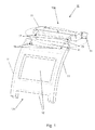
- the Fig. 1 shows a section of a three-dimensional representation of a stepped slotted bearing cage 10 according to one embodiment.
- the bearing cage 10 has two circumferentially extending and axially spaced side rings 11, between which pockets 12 may be arranged for receiving (not shown) rolling elements or are arranged.
- the slotted bearing cage 10 is slotted in the circumferential direction, which is also referred to below as a tangential direction, at least one separation point or a slot between a first and a second bearing cage portion 13a and 13b.
- a pair of a first projection 15 and a corresponding first recess 16 is provided, which is designed to the bearing cage sections 13a, 13b primarily in a first (here: axial) direction to fix.
- a first projection 15 and the first recess 16 are provided at opposite boundary surfaces of the first projection 15 and the first recess 16 corresponding thereto, at least one pair of a second projection 17 and a corresponding thereto second recess 18 is formed or formed, which is formed to the bearing cage sections 13a, 13b to each other in at least two additional directions (here: radial and tangential) to fix.
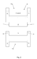
- the integrally formed at the separation point and pointing in the circumferential direction first projection 15 may have a substantially rectangular cross-section perpendicular and parallel to the axis of rotation of the bearing cage 10.
- the first recess 16 can be a parallelepiped-shaped recess lying opposite it or a cuboid-shaped cavity in the second bearing cage section 13b.
- a second projection 17 has a direction perpendicular to the direction of projection of the first projection 15.
- second projections 17 are integrally formed on the two boundary surfaces of the first projection 15, which point in the axial direction, in the tangential direction. Accordingly, in the two facing in the axial direction boundary surfaces of the first recess 16 to the second projections 17 corresponding second recesses 18 are formed.
- additionally or alternatively also on radial boundary surfaces of the first projection 15 and the first recess 16 further pairs of second projections 17 and recesses 18 on or be formed.
- the at least one second projection 17 may, according to some embodiments, have a substantially semicircular to circular cross-section parallel to the axis of rotation of the bearing cage 10, wherein a second recess 18 corresponding to the at least one second projection 17 has a spherical shape adapted to the substantially semicircular to circular cross-section Cross-section parallel to the axis of rotation of the bearing cage 10 may have.
- a second projection 17 may have a substantially hemispherical to spherical geometry.
- a second recess 18 would then have a substantially hemispherical to spherical sphere.
- spherical geometries may be advantageous in view of an embodiment with excess of the second projections 17 relative to the second recesses 18.
- the two bearing cage sections 13a and 13b of the stepped slotted bearing cage 10 can advantageously be in all three directions, ie axially, tangentially and radially, fixed to each other.
- the strength of the respective fixation can be adjusted by the respective geometries of the projections 15, 17 and recesses 16, 18.
- the first projection 15 may have a (slight) oversize in the axial direction relative to the first recess 16 corresponding thereto, such that upon insertion of the first projection 15 into the first recess 16 a kind of interference fit of Bearing cage portions 13a and 13b may be formed to fix the bearing cage portions 13a, 13b at the separation point in the axial direction to each other.
- this presupposes a certain elasticity, but this is generally the case with plastic bearing cages.
- the second projections 17 and the corresponding thereto second recesses 18 may well take smaller dimensions than in embodiments without the described axial interference fit. Accordingly, the dimensions of the second projections 17 and recesses 18 can be adjusted to obtain a strong or rather weaker radial / tangential fixation of the two bearing cage sections 13a, 13b.
- the dimensions of the projections 15, 17 and the recesses 16, 18 described in the present specification can also be chosen quite differently in order to adapt a stepped slotted bearing cage design to its radial, tangential and / or axial loads.
- a plurality of juxtaposed first projections 15 could be arranged between the axially outer first side rings 11, for example. The same applies, of course, also for the corresponding first recess 16.
- Embodiments of the slotted bearing cage 10 described herein may be made of plastic, for example.
- the stepped slotted bearing cage 10 can be produced in particular by means of a plastic injection molding process. With only one separation point in an annular bearing cage, the bearing cage 10 may also be an integrally molded injection molded part.
- stepped slotted bearing cages can be used in rolling bearings, so that embodiments of the present invention also include rolling bearings with bearing cages according to the invention.
- embodiments of the present invention relate to a stepped slotted plastic cage with lock.
- the stepped slot shape can ensure a fixation of the open sides or portions in the axial direction and prevent mutual displacement.
- the lock comprising recesses 16, 18, for example, on a slot side and the projections 15, 17, for example on the other slot side, can prevent a gap after a mounting process "radial / axial snapping a roller ring on a shaft” and a positive connection between open slot sides.
- the combination "stepped slot + lock” is a fixation of the bearing cage sections in the axial, radial and tangential direction.
Landscapes
- Engineering & Computer Science (AREA)
- General Engineering & Computer Science (AREA)
- Mechanical Engineering (AREA)
- Rolling Contact Bearings (AREA)
Applications Claiming Priority (1)
| Application Number | Priority Date | Filing Date | Title |
|---|---|---|---|
| DE102011080168.5A DE102011080168B4 (de) | 2011-08-01 | 2011-08-01 | Konzept für einen geschlitzten Lagerkäfig |
Publications (1)
| Publication Number | Publication Date |
|---|---|
| EP2554862A1 true EP2554862A1 (fr) | 2013-02-06 |
Family
ID=46982387
Family Applications (1)
| Application Number | Title | Priority Date | Filing Date |
|---|---|---|---|
| EP12178844A Withdrawn EP2554862A1 (fr) | 2011-08-01 | 2012-08-01 | Verrouillage entre les bouts d'une cage de roulement à fente |
Country Status (4)
| Country | Link |
|---|---|
| US (1) | US8894293B2 (fr) |
| EP (1) | EP2554862A1 (fr) |
| CN (1) | CN103032470A (fr) |
| DE (1) | DE102011080168B4 (fr) |
Cited By (1)
| Publication number | Priority date | Publication date | Assignee | Title |
|---|---|---|---|---|
| WO2017178004A1 (fr) * | 2016-04-12 | 2017-10-19 | Schaeffler Technologies AG & Co. KG | Cage de roulement et procédé de montage pour une cage de roulement |
Families Citing this family (25)
| Publication number | Priority date | Publication date | Assignee | Title |
|---|---|---|---|---|
| US9623474B2 (en) * | 2012-05-16 | 2017-04-18 | Aktiebolaget Skf | Split bearing cage for rolling element bearing |
| JP6269021B2 (ja) * | 2013-12-17 | 2018-01-31 | 日本精工株式会社 | ラジアルころ軸受用保持器 |
| DE102014205975B4 (de) | 2014-03-31 | 2018-03-15 | Skf Lubrication Systems Germany Gmbh | Schmiermittelinjektor |
| CN105333016A (zh) * | 2014-06-25 | 2016-02-17 | 舍弗勒技术股份两合公司 | K形保持架轴承 |
| DE102016211906A1 (de) | 2016-06-30 | 2018-01-04 | Aktiebolaget Skf | Käfig für Kurbelwellenlagerung |
| DE102016211908A1 (de) * | 2016-06-30 | 2018-01-04 | Aktiebolaget Skf | Geteilter Lagerkäfig |
| DE102017100489A1 (de) | 2017-01-12 | 2018-07-12 | Schaeffler Technologies AG & Co. KG | Lagerkäfig für Wälzlager |
| DE102017101034A1 (de) | 2017-01-20 | 2018-07-26 | Schaeffler Technologies AG & Co. KG | Lagerkäfig für Wälzlager mit Käfigsegmenten |
| DE102017109141A1 (de) | 2017-04-28 | 2018-10-31 | Schaeffler Technologies AG & Co. KG | Lagerkäfig für Wälzlager mit Käfigabschnitten |
| DE102017212688A1 (de) | 2017-07-24 | 2019-01-24 | Aktiebolaget Skf | Lagerkäfig, Radiallageranordnung mit einem solchen Käfig, insbesondere für eine Ausgleichswelle |
| DE102017217810A1 (de) * | 2017-10-06 | 2019-04-11 | Aktiebolaget Skf | Anordnung für ein Wälzlager |
| CN110848265A (zh) * | 2018-08-20 | 2020-02-28 | 广东威灵电机制造有限公司 | 滚动轴承和电机 |
| CN111113039A (zh) * | 2018-11-01 | 2020-05-08 | 山东金帝精密机械科技股份有限公司 | 一种风力发电轴承保持架制造方法及设备 |
| DE102019201560A1 (de) | 2019-02-07 | 2020-08-13 | Aktiebolaget Skf | Lagerkäfigsegment mit Stoßkante zum Verschweißen |
| DE102019201561A1 (de) | 2019-02-07 | 2020-08-13 | Aktiebolaget Skf | Lagerkäfigsegment eines Metallblechkäfigs |
| DE102019201565A1 (de) | 2019-02-07 | 2020-08-13 | Aktiebolaget Skf | Lagerkäfigsegment mit einer Stoßkante im Bereich eines zu bildenden Stegs |
| DE102019201553A1 (de) * | 2019-02-07 | 2020-08-13 | Aktiebolaget Skf | Lagerkäfigsegment mit Ausrichtungselement |
| CN111779765A (zh) * | 2020-05-19 | 2020-10-16 | 上海涟屹轴承科技有限公司 | 一种舰船变速箱用径向轴承结构 |
| DE102021206285A1 (de) | 2021-06-18 | 2022-12-22 | Aktiebolaget Skf | Käfigsegment für einen Wälzlagerkäfig |
| DE102021206284A1 (de) | 2021-06-18 | 2022-12-22 | Aktiebolaget Skf | Käfigsegment für einen Wälzlagerkäfig |
| DE102021206282A1 (de) | 2021-06-18 | 2022-12-22 | Aktiebolaget Skf | Käfigsegment für einen Wälzlagerkäfig |
| DE102022200326A1 (de) | 2022-01-13 | 2023-07-13 | Aktiebolaget Skf | Käfigsegment für einen Segmentkäfig |
| DE102022200327A1 (de) | 2022-01-13 | 2023-07-13 | Aktiebolaget Skf | Lagerkäfig |
| CN114483793B (zh) * | 2022-01-28 | 2024-04-23 | 中国铁建重工集团股份有限公司 | 一种轴承保持装置 |
| CN114562517B (zh) * | 2022-03-11 | 2024-03-26 | 河南科技大学 | 一种轴承保持架及盾构机主轴承 |
Citations (11)
| Publication number | Priority date | Publication date | Assignee | Title |
|---|---|---|---|---|
| US3399008A (en) * | 1966-06-15 | 1968-08-27 | Skf Ind Inc | Roller cage assembly |
| DE2906128A1 (de) * | 1979-02-17 | 1980-08-28 | Schaeffler Ohg Industriewerk | Kaefigsegment fuer vierpunktkugellager, insbesondere drahtkugellager grossen durchmessers |
| US4472007A (en) * | 1983-04-04 | 1984-09-18 | The Torrington Company | Cage assembly |
| JPS59163223U (ja) * | 1983-04-18 | 1984-11-01 | 株式会社不二越 | 2つ割り保持器 |
| JPS6024932U (ja) * | 1983-07-27 | 1985-02-20 | 光洋精工株式会社 | ころがり軸受用合成樹脂製保持器 |
| DE3526625A1 (de) * | 1985-07-25 | 1987-01-29 | Skf Gmbh | Segmentkaefig fuer waelzlager |
| JPH0276222U (fr) * | 1988-11-30 | 1990-06-12 | ||
| JPH10281165A (ja) * | 1997-04-03 | 1998-10-20 | Nippon Seiko Kk | 転がり軸受用の保持器 |
| JP2003013964A (ja) * | 2001-06-27 | 2003-01-15 | Ntn Corp | 超薄肉形転がり軸受およびその保持器 |
| US20060204159A1 (en) * | 2005-03-14 | 2006-09-14 | Yoon Suk T | Self-locking structure of split roller bearing cage |
| JP2008019974A (ja) * | 2006-07-12 | 2008-01-31 | Nsk Ltd | スラスト玉軸受用保持器 |
Family Cites Families (16)
| Publication number | Priority date | Publication date | Assignee | Title |
|---|---|---|---|---|
| US4239304A (en) * | 1979-03-28 | 1980-12-16 | The Torrington Company | Bearing split cage |
| JPS56166321U (fr) * | 1980-05-15 | 1981-12-09 | ||
| JPS56166321A (en) * | 1980-05-27 | 1981-12-21 | Nippon Steel Corp | Manufacture of nonrefined high tensile steel |
| DE3041860A1 (de) | 1980-11-06 | 1982-06-03 | Industriewerk Schaeffler Ohg, 8522 Herzogenaurach | Kunststoffkaefig fuer waelzlager |
| DE8621532U1 (de) * | 1986-08-11 | 1987-12-23 | Gugel, Georg, Dipl.-Ing., 8552 Höchstadt | Käfigelement für Kreuzrollenlager |
| DE3709039C2 (de) * | 1987-03-19 | 1994-01-27 | Skf Linearsysteme Gmbh | Käfig für Längsbewegungen ausführende Rollenlager |
| US4865473A (en) | 1988-09-06 | 1989-09-12 | The Torrington Company | Single split cage locking tab |
| DE3911671A1 (de) * | 1989-04-10 | 1990-10-11 | Schaeffler Waelzlager Kg | Waelzlagerkaefig |
| DE4007452A1 (de) * | 1990-03-09 | 1991-09-12 | Legrom Gmbh | Lagerkaefig |
| DE4211400C2 (de) * | 1992-04-04 | 1999-12-02 | Schaeffler Waelzlager Ohg | Käfig für ein Wälzlager oder für eine Linearführung |
| JP3811575B2 (ja) * | 1998-10-29 | 2006-08-23 | 株式会社ジェイテクト | 軸受用保持器 |
| DE10011651B4 (de) * | 2000-03-10 | 2009-12-24 | Schaeffler Kg | Rotationssymmetrisches Formteil |
| DE10065169A1 (de) * | 2000-12-23 | 2002-07-04 | Fag Ind Bearings Ag | Blechkäfig für Wälzlager |
| DE102007048655A1 (de) * | 2007-10-10 | 2008-02-07 | Schaeffler Kg | Käfigsegment eines Kunststoffkäfigs sowie Wälzlager mit dem Kunststoffkäfig |
| JP2010242966A (ja) * | 2009-03-16 | 2010-10-28 | Jtekt Corp | 保持器付き針状ころ軸受 |
| CN201636213U (zh) * | 2010-03-16 | 2010-11-17 | 大连三木得科技有限公司 | 一种碳纤维复合材料的新型轴承保持架 |
-
2011
- 2011-08-01 DE DE102011080168.5A patent/DE102011080168B4/de active Active
-
2012
- 2012-07-23 US US13/555,820 patent/US8894293B2/en active Active
- 2012-08-01 EP EP12178844A patent/EP2554862A1/fr not_active Withdrawn
- 2012-08-01 CN CN2012103955091A patent/CN103032470A/zh active Pending
Patent Citations (11)
| Publication number | Priority date | Publication date | Assignee | Title |
|---|---|---|---|---|
| US3399008A (en) * | 1966-06-15 | 1968-08-27 | Skf Ind Inc | Roller cage assembly |
| DE2906128A1 (de) * | 1979-02-17 | 1980-08-28 | Schaeffler Ohg Industriewerk | Kaefigsegment fuer vierpunktkugellager, insbesondere drahtkugellager grossen durchmessers |
| US4472007A (en) * | 1983-04-04 | 1984-09-18 | The Torrington Company | Cage assembly |
| JPS59163223U (ja) * | 1983-04-18 | 1984-11-01 | 株式会社不二越 | 2つ割り保持器 |
| JPS6024932U (ja) * | 1983-07-27 | 1985-02-20 | 光洋精工株式会社 | ころがり軸受用合成樹脂製保持器 |
| DE3526625A1 (de) * | 1985-07-25 | 1987-01-29 | Skf Gmbh | Segmentkaefig fuer waelzlager |
| JPH0276222U (fr) * | 1988-11-30 | 1990-06-12 | ||
| JPH10281165A (ja) * | 1997-04-03 | 1998-10-20 | Nippon Seiko Kk | 転がり軸受用の保持器 |
| JP2003013964A (ja) * | 2001-06-27 | 2003-01-15 | Ntn Corp | 超薄肉形転がり軸受およびその保持器 |
| US20060204159A1 (en) * | 2005-03-14 | 2006-09-14 | Yoon Suk T | Self-locking structure of split roller bearing cage |
| JP2008019974A (ja) * | 2006-07-12 | 2008-01-31 | Nsk Ltd | スラスト玉軸受用保持器 |
Cited By (1)
| Publication number | Priority date | Publication date | Assignee | Title |
|---|---|---|---|---|
| WO2017178004A1 (fr) * | 2016-04-12 | 2017-10-19 | Schaeffler Technologies AG & Co. KG | Cage de roulement et procédé de montage pour une cage de roulement |
Also Published As
| Publication number | Publication date |
|---|---|
| US8894293B2 (en) | 2014-11-25 |
| CN103032470A (zh) | 2013-04-10 |
| DE102011080168A1 (de) | 2013-02-07 |
| US20130034321A1 (en) | 2013-02-07 |
| DE102011080168B4 (de) | 2022-06-30 |
Similar Documents
| Publication | Publication Date | Title |
|---|---|---|
| DE102011080168B4 (de) | Konzept für einen geschlitzten Lagerkäfig | |
| DE102011005407B4 (de) | Konzept für einen geschlitzten Lagerkäfig | |
| DE102011082809B4 (de) | Verbindungskonzept für einen geteilten Lagerkäfig | |
| DE102009006859B3 (de) | Wälzlagerkäfig | |
| EP2473748A1 (fr) | Cage pour un palier de roulement et palier de roulement | |
| DE102017115881A1 (de) | Wälzlagerkäfig | |
| DE102015220363A1 (de) | Zweiteiliger Lagerkäfig | |
| DE102009006858A1 (de) | Wälzlagerkäfig | |
| DE112014000561B4 (de) | Käfig für ein Wälzlager, insbesondere für ein Lager für eine elektrische Kraftfahrzeugservolenkung | |
| EP2203654A1 (fr) | Roulement avec une bague de roulement divisée | |
| DE112015004978T5 (de) | Kegelrollenlager | |
| DE202017106205U1 (de) | Klemmkörperfreilauf mit Fliehkraftabhebung | |
| WO2015139694A1 (fr) | Cage de roulement pour roulement à rouleaux coniques | |
| DE102010042849B4 (de) | Lagerkäfig und Verfahren zur Herstellung desselben | |
| DE112015004945T5 (de) | Kegelrollenlager | |
| DE102017126701A1 (de) | Wälzlagerkäfig | |
| DE102013214245A1 (de) | Geteilter Wälzkörperkäfig | |
| DE102020001789A1 (de) | Lagerbuchse und Herstellungsverfahren einer Lagerbuchse | |
| DE102011088720A1 (de) | Wälzlagerkäfig | |
| DE102008028371B4 (de) | Toleranzring | |
| DE102013016177B4 (de) | Käfig für ein Wälzlager, insbesondere für ein Lager einer elektrischen Servolenkung eines Kraftfahrzeugs | |
| DE102011006031B4 (de) | Segment für einen Wälzlagerkäfig und Verfahren zu dessen Herstellung | |
| EP2687740A1 (fr) | Verrouillage entre les bouts d'une cage de roulement à fente | |
| DE112015004946T5 (de) | Kegelrollenlager | |
| DE102014210247B4 (de) | Lagerkäfig |
Legal Events
| Date | Code | Title | Description |
|---|---|---|---|
| PUAI | Public reference made under article 153(3) epc to a published international application that has entered the european phase |
Free format text: ORIGINAL CODE: 0009012 |
|
| AK | Designated contracting states |
Kind code of ref document: A1 Designated state(s): AL AT BE BG CH CY CZ DE DK EE ES FI FR GB GR HR HU IE IS IT LI LT LU LV MC MK MT NL NO PL PT RO RS SE SI SK SM TR |
|
| AX | Request for extension of the european patent |
Extension state: BA ME |
|
| RBV | Designated contracting states (corrected) |
Designated state(s): AL AT BE BG CH CY CZ DE DK EE ES FI FR GB GR HR HU IE IS IT LI LT LU LV MC MK MT NL NO PL PT RO RS SE SI SK SM TR |
|
| 17P | Request for examination filed |
Effective date: 20130802 |
|
| STAA | Information on the status of an ep patent application or granted ep patent |
Free format text: STATUS: REQUEST FOR EXAMINATION WAS MADE |
|
| STAA | Information on the status of an ep patent application or granted ep patent |
Free format text: STATUS: THE APPLICATION IS DEEMED TO BE WITHDRAWN |
|
| 18D | Application deemed to be withdrawn |
Effective date: 20170301 |