EP2554881B1 - Hochtemperaturdichtung - Google Patents
Hochtemperaturdichtung Download PDFInfo
- Publication number
- EP2554881B1 EP2554881B1 EP12005435.8A EP12005435A EP2554881B1 EP 2554881 B1 EP2554881 B1 EP 2554881B1 EP 12005435 A EP12005435 A EP 12005435A EP 2554881 B1 EP2554881 B1 EP 2554881B1
- Authority
- EP
- European Patent Office
- Prior art keywords
- ring
- sealing ring
- counter
- sealing
- temperature seal
- Prior art date
- Legal status (The legal status is an assumption and is not a legal conclusion. Google has not performed a legal analysis and makes no representation as to the accuracy of the status listed.)
- Not-in-force
Links
- 238000007789 sealing Methods 0.000 claims description 49
- 229910000831 Steel Inorganic materials 0.000 claims description 4
- 239000010959 steel Substances 0.000 claims description 4
- 229910003336 CuNi Inorganic materials 0.000 claims description 3
- 239000000956 alloy Substances 0.000 claims description 3
- 229910045601 alloy Inorganic materials 0.000 claims description 3
- 239000002184 metal Substances 0.000 claims description 3
- 239000000463 material Substances 0.000 description 8
- 230000013011 mating Effects 0.000 description 8
- UGFAIRIUMAVXCW-UHFFFAOYSA-N Carbon monoxide Chemical compound [O+]#[C-] UGFAIRIUMAVXCW-UHFFFAOYSA-N 0.000 description 4
- 239000003546 flue gas Substances 0.000 description 4
- 238000010438 heat treatment Methods 0.000 description 4
- 230000002349 favourable effect Effects 0.000 description 3
- 239000007789 gas Substances 0.000 description 3
- 238000001035 drying Methods 0.000 description 2
- 238000009434 installation Methods 0.000 description 2
- OKTJSMMVPCPJKN-UHFFFAOYSA-N Carbon Chemical compound [C] OKTJSMMVPCPJKN-UHFFFAOYSA-N 0.000 description 1
- 229910052799 carbon Inorganic materials 0.000 description 1
- 239000000919 ceramic Substances 0.000 description 1
- 230000007423 decrease Effects 0.000 description 1
- 210000003746 feather Anatomy 0.000 description 1
- 239000007788 liquid Substances 0.000 description 1
- 230000036316 preload Effects 0.000 description 1
- 230000001105 regulatory effect Effects 0.000 description 1
- HBMJWWWQQXIZIP-UHFFFAOYSA-N silicon carbide Chemical compound [Si+]#[C-] HBMJWWWQQXIZIP-UHFFFAOYSA-N 0.000 description 1
- 229910010271 silicon carbide Inorganic materials 0.000 description 1
Images



Classifications
-
- F—MECHANICAL ENGINEERING; LIGHTING; HEATING; WEAPONS; BLASTING
- F16—ENGINEERING ELEMENTS AND UNITS; GENERAL MEASURES FOR PRODUCING AND MAINTAINING EFFECTIVE FUNCTIONING OF MACHINES OR INSTALLATIONS; THERMAL INSULATION IN GENERAL
- F16J—PISTONS; CYLINDERS; SEALINGS
- F16J15/00—Sealings
- F16J15/16—Sealings between relatively-moving surfaces
- F16J15/34—Sealings between relatively-moving surfaces with slip-ring pressed against a more or less radial face on one member
-
- F—MECHANICAL ENGINEERING; LIGHTING; HEATING; WEAPONS; BLASTING
- F16—ENGINEERING ELEMENTS AND UNITS; GENERAL MEASURES FOR PRODUCING AND MAINTAINING EFFECTIVE FUNCTIONING OF MACHINES OR INSTALLATIONS; THERMAL INSULATION IN GENERAL
- F16J—PISTONS; CYLINDERS; SEALINGS
- F16J15/00—Sealings
- F16J15/16—Sealings between relatively-moving surfaces
- F16J15/34—Sealings between relatively-moving surfaces with slip-ring pressed against a more or less radial face on one member
- F16J15/3464—Mounting of the seal
-
- F—MECHANICAL ENGINEERING; LIGHTING; HEATING; WEAPONS; BLASTING
- F16—ENGINEERING ELEMENTS AND UNITS; GENERAL MEASURES FOR PRODUCING AND MAINTAINING EFFECTIVE FUNCTIONING OF MACHINES OR INSTALLATIONS; THERMAL INSULATION IN GENERAL
- F16J—PISTONS; CYLINDERS; SEALINGS
- F16J15/00—Sealings
- F16J15/16—Sealings between relatively-moving surfaces
- F16J15/26—Sealings between relatively-moving surfaces with stuffing-boxes for rigid sealing rings
- F16J15/28—Sealings between relatively-moving surfaces with stuffing-boxes for rigid sealing rings with sealing rings made of metal
-
- F—MECHANICAL ENGINEERING; LIGHTING; HEATING; WEAPONS; BLASTING
- F16—ENGINEERING ELEMENTS AND UNITS; GENERAL MEASURES FOR PRODUCING AND MAINTAINING EFFECTIVE FUNCTIONING OF MACHINES OR INSTALLATIONS; THERMAL INSULATION IN GENERAL
- F16J—PISTONS; CYLINDERS; SEALINGS
- F16J15/00—Sealings
- F16J15/16—Sealings between relatively-moving surfaces
- F16J15/34—Sealings between relatively-moving surfaces with slip-ring pressed against a more or less radial face on one member
- F16J15/3496—Sealings between relatively-moving surfaces with slip-ring pressed against a more or less radial face on one member use of special materials
-
- F—MECHANICAL ENGINEERING; LIGHTING; HEATING; WEAPONS; BLASTING
- F27—FURNACES; KILNS; OVENS; RETORTS
- F27B—FURNACES, KILNS, OVENS OR RETORTS IN GENERAL; OPEN SINTERING OR LIKE APPARATUS
- F27B7/00—Rotary-drum furnaces, i.e. horizontal or slightly inclined
- F27B7/20—Details, accessories or equipment specially adapted for rotary-drum furnaces
-
- F—MECHANICAL ENGINEERING; LIGHTING; HEATING; WEAPONS; BLASTING
- F27—FURNACES; KILNS; OVENS; RETORTS
- F27B—FURNACES, KILNS, OVENS OR RETORTS IN GENERAL; OPEN SINTERING OR LIKE APPARATUS
- F27B7/00—Rotary-drum furnaces, i.e. horizontal or slightly inclined
- F27B7/20—Details, accessories or equipment specially adapted for rotary-drum furnaces
- F27B7/22—Rotary drums; Supports therefor
- F27B7/24—Seals between rotary and stationary parts
Definitions
- the invention relates to a high-temperature seal between a rotating about a central axis part and a fixed part with a sealing ring and a counter-ring, wherein the sealing ring has a slope and forms with the mating ring a sliding and sealing surface which is perpendicular to the central axis of the rotating part , Furthermore, the invention relates to a rotary tube reactor with a high-temperature seal.
- the EP 0 992 722 A2 a mechanical seal for sealing rotating parts against liquids, in which case slip ring and counter ring made of carbon or silicon carbide.
- the EP 0 255 662 A2 shows a seal among other things for drum ovens. Here is a steel seal ring on a metallic counter ring. The large sealing surface also results in high friction.
- the DE 40 35 129 A1 shows a mechanical seal for rotary tubular drums, in which a profiled sealing ring runs in a contoured groove. Again, a high friction occurs.
- the aim of the invention is therefore to provide a sealing system for use at high temperatures, which is stable and seals well at all temperatures.
- the invention is therefore characterized in that the sealing ring and mating ring are made of metal, wherein the sealing ring is fixed and the rotating part fixed to the mating ring rotates about the central axis of the rotating part, wherein the sealing ring of a high-grade steel and the mating ring of a CuNi alloy can exist.
- This allows the parts even at high Temperatures slide on each other without gaps and the forces on the sealing ring can be adjusted very well.
- a favorable development of the invention is characterized in that the sealing ring is pressed against the counter ring by a positioning ring. This adjusting ring makes it easy to control the contact pressure.
- a favorable embodiment of the invention is characterized in that the sealing ring, in particular via an adjusting ring, is pressed by a compensator against the counter ring. Due to the bias of the contact pressure can be regulated accordingly and it can also axial movements and thermal expansion between rotating and stationary part can be compensated.
- An advantageous embodiment of the invention is characterized in that the sealing ring is clamped on the adjusting ring. This ensures that the sealing ring slides on the mating ring.
- the invention also relates to a rotary tubular reactor with a high-temperature seal according to the invention.
- the rotary tube reactor is characterized in that the counter-ring is attached to the reactor drum and this rotates in operation, wherein the sealing ring is advantageously connected to the fixed part.
- Fig. 1 shows an inventive arrangement of a high-temperature seal 1 between about a central axis 2 rotating part 3, which may be, for example, a rotary tube reactor or a heated drying drum, and a fixed part 4, for example, a supply nozzle for a material supply or a connection for supplying a heating gas, eg flue gas ,
- a sealing ring 5 is pressed against the stationary part 4 against a counter ring 6 on the rotating part 3.
- a compensator 7 serves to preload and to compensate for axial movements and strains.
- feather keys 8 eg, two or more distributed over the circumference
- Fig. 2 a section through a high-temperature seal 1 according to the invention is shown, wherein like parts are provided with the same reference numerals.
- the core element of the high-temperature seal 1 is the sealing ring 5, which consists for example of a high-grade steel.
- the sealing ring 5 is located on the fixed part 4 and therefore does not turn.
- the compensator 7 is preferably designed as a metal compensator and presses the sealing ring 5 via a Anstellring 10 to the mating ring 6.
- the compensator 7 is biased accordingly. In addition, it still compensates for movements in the axial direction as well as thermal expansions between the rotating part 3 and the stationary part 4.
- the counter-ring 6 consists for example of a soft CuNi alloy, is attached to the rotating part 3 and forms with the sealing ring 5, the sliding and sealing surface 9. Since the sliding and sealing surface 9 is at right angles to the central axis 2, radial movements and Thermal expansion over the sliding and sealing surface 9 balanced. By the biasing force of the compensator 7, the sealing ring 5 changes its inclination and the inner diameter decreases slightly. Now, if the material of the sealing ring 5 has a smaller coefficient of thermal expansion than the material of the Anstellrings 10, there is a jamming of the sealing ring 5 on Anstellring 10. This ensures that the sealing ring 5 slides on the mating ring 6 instead of the Anstellring 10.
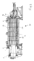
- Fig. 3 now shows a rotary tube reactor 11 which is heated by flue gas, wherein the flue gas fed to a chamber 12 and heated via a double jacket 13 and heating tubes 14 material in the interior of the drum 15.
- the flue gas has temperatures of up to 450 ° C while the material in the interior of the drum 15 is heated up to about 400 ° C.
- two high-temperature seals 1 are provided at both ends of the drum 15.
- Fig. 4 a shows the installation situation in the region of the material discharge, the sealing ring 5 'being pressed against the counter ring 6' via a compensator 7 'and an adjusting ring 10'.
- the situation on the outer periphery of the rotary tube reactor 11 is in Fig. 4b shown.
- the sealing ring 5 is pressed over a compensator 7" and an adjusting ring 10 "to the counter ring 6".
- Fig. 4c the installation situation is shown in the material supply, in which case two high-temperature seals 1 according to the invention are used here.
- the high-temperature seal according to the invention can be used in all applications in which rotating parts at high temperatures (above 80 to 100 ° C and up to 1200 ° C) must be sealed against fixed parts.
Landscapes
- Engineering & Computer Science (AREA)
- General Engineering & Computer Science (AREA)
- Mechanical Engineering (AREA)
- Muffle Furnaces And Rotary Kilns (AREA)
- Gasket Seals (AREA)
- Mechanical Sealing (AREA)
- Sealing Devices (AREA)
Description
- Die Erfindung betrifft eine Hochtemperaturdichtung zwischen einem um eine Mittelachse rotierenden Teil und einem feststehenden Teil mit einem Dichtring und einem Gegenring, wobei der Dichtring eine Neigung aufweist und mit dem Gegenring eine Gleit- und Dichtfläche bildet, die im rechten Winkel zur Mittelachse des rotierenden Teils steht. Weiters betrifft die Erfindung einen Drehrohrreaktor mit einer Hochtemperaturdichtung.
- Bei Apparaten, bei denen im Betrieb hohe Temperaturen auftreten, z.B. Drehrohrreaktoren oder Trommeltrocknern, besteht immer wieder das Problem einer Abdichtung der rotierenden Teile, insbesondere der Trommel, gegen die feststehenden Teile, wie entsprechende Zuführstutzen oder Abdeckungen für Gase. So wird oft Falschluft durch Spalte eingesaugt und die Trommel muss gegenüber der Umgebung einen geringen Unterdruck aufweisen. Diese Falschluft verringert die Wärmekapazität der Trocknungs- oder Heizgase und erfordert einen zusätzlichen Heizaufwand. Bei diesen hohen Temperaturen werden meist Keramikdichtungen eingesetzt, die jedoch brüchig sind und nur schwer ausgetauscht werden können. Auch ist aus der gattungsgemäßen
EP 1 398 549 A1 eine Gleitringdichtung zur Abdichtung von Bauteilen mit hoher Temperaturbeaufschlagung bekannt. Der Einsatz für höhere Temperaturen (bis zu 1200 °C) ist allerdings stark beschränkt, da hier elastische Dichtkörper zum Einsatz kommen. Weiters zeigt u.a. dieEP 0 992 722 A2 eine Gleitringdichtung zur Abdichtung von drehenden Teilen gegen Flüssigkeiten, wobei hier Gleitring und Gegenring aus Kohle bzw. Siliciumcarbid bestehen. DieEP 0 255 662 A2 zeigt eine Dichtung u.a. für Trommelöfen. Hier läuft ein stählemer Dichtungsring auf einem metallischen Gegenring. Die große Dichtfläche ergibt auch eine hohe Reibung. DieDE 40 35 129 A1 zeigt eine Gleitringdichtung für Drehrohrtrommeln, bei der ein profilierter Dichtring in einer konträr geformten Nut läuft. Auch hier tritt eine hohe Reibung auf. - Ziel der Erfindung ist es daher ein Dichtungssystem für die Anwendung bei hohen Temperaturen zu schaffen, das stabil ist und bei allen Temperaturen gut abdichtet.
- Die Erfindung ist daher dadurch gekennzeichnet, dass der Dichtring und Gegenring aus Metall bestehen, wobei der Dichtring feststeht und der am rotierenden Teil befestigte Gegenring um die Mittelachse des rotierenden Teils rotiert, wobei der Dichtring aus einem hochwertigen Stahl und der Gegenring aus einer CuNi-Legierung bestehen kann. Dadurch können die Teile auch bei hohen Temperaturen aufeinander gleiten ohne Spalte zu lassen und es können die Kräfte auf den Dichtring sehr gut eingestellt werden.
- Eine günstige Weiterbildung der Erfindung ist dadurch gekennzeichnet, dass der Dichtring durch einen Anstellring gegen den Gegenring angedrückt wird. Durch diesen Anstellring lässt sich die Anpresskraft gut kontrollieren.
- Eine günstige Ausgestaltung der Erfindung ist dadurch gekennzeichnet, dass der Dichtring, insbesondere über einen Anstellring, durch einen Kompensator an den Gegenring gedrückt wird. Durch die Vorspannung kann der Anpressdruck entsprechend reguliert werden und es können auch axiale Bewegungen sowie Temperaturdehnungen zwischen drehendem und feststehendem Teil ausgeglichen werden.
- Eine vorteilhafte Ausgestaltung der Erfindung ist dadurch gekennzeichnet, dass der Dichtring am Anstellring verklemmt ist. Dadurch wird sichergestellt, dass der Dichtring am Gegenring gleitet.
- Die Erfindung betrifft auch einen Drehrohrreaktor mit einer erfindungsgemäßen Hochtemperaturdichtung. Der Drehrohrreaktor ist dadurch gekennzeichnet, dass der Gegenring an der Reaktortrommel befestigt ist und diese im Betrieb rotiert, wobei der Dichtring vorteilhafterweise mit dem feststehenden Teil verbunden ist.
- Besonders günstig ist es, wenn beim Drehrohrreaktor zumindest an beiden Enden eine Hochtemperaturdichtung vorgesehen ist.
- Die Erfindung wird nun anhand der Zeichnungen beispielhaft beschrieben, wobei
-
Fig. 1 eine Ansicht einer erfindungsgemäßen Dichtanordnung, -
Fig. 2 einen Schnitt durch eine erfindungsgemäße Dichtanordnung, -
Fig. 3 eine Ansicht eines Drehrohrreaktors mit erfindungsgemäßer Hochtemperaturdichtung und -
Fig. 4a, b und c Details der Dichtanordnung beim Drehrohrreaktor derFig. 3 darstellen. -
Fig. 1 zeigt eine erfindungsgemäße Anordnung einer Hochtemperaturdichtung 1 zwischen einem um eine Mittelachse 2 rotierenden Teil 3, der z.B. ein Drehrohrreaktor oder eine beheizte Trockentrommel sein kann, und einem feststehenden Teil 4, beispielsweise eines Zufuhrstutzens für eine Materialzufuhr oder eines Anschlusses zur Zufuhr eines Heizgases, z.B. Rauchgas. Hierbei wird ein Dichtring 5 am stehenden Teil 4 gegen einen Gegenring 6 am rotierenden Teil 3 gedrückt. Ein Kompensator 7 dient zur Vorspannung und zum Ausgleich von axialen Bewegungen und Dehnungen. Durch Passfedern 8 (z. B. zwei oder mehr über den Umfang verteilt) wird verhindert, dass der Kompensator 7 das Drehmoment aufnehmen muss, das durch die Reibkraft des Dichtrings 5 auf der Gleitfläche 9 des Gegenrings 6 entsteht. - In
Fig. 2 ist ein Schnitt durch eine erfindungsgemäße Hochtemperaturdichtung 1 dargestellt, wobei gleiche Teile mit gleichen Bezugszeichen versehen sind. Das Kernelement der Hochtemperaturdichtung 1 ist der Dichtring 5, der beispielsweise aus einem hochwertigen Stahl besteht. Der Dichtring 5 befindet sich am feststehenden Teil 4 und dreht daher nicht. Der Kompensator 7 ist vorzugsweise als Metallkompensator ausgeführt und drückt den Dichtring 5 über einen Anstellring 10 an den Gegenring 6. Der Kompensator 7 wird dazu entsprechend vorgespannt. Zusätzlich gleicht er noch Bewegungen in axialer Richtung sowie Temperaturdehnungen zwischen rotierendem Teil 3 und feststehendem Teil 4 aus. Der Gegenring 6 besteht beispielsweise aus einer weichen CuNi-Legierung, ist am rotierenden Teil 3 befestigt und bildet mit dem Dichtring 5 die Gleit- und Dichtfläche 9. Da die Gleit- und Dichtfläche 9 im rechten Winkel zur Mittelachse 2 steht, werden radiale Bewegungen und Temperaturdehnungen über die Gleit- und Dichtfläche 9 ausgeglichen. Durch die Vorspannkraft des Kompensators 7 verändert der Dichtring 5 seine Neigung und der Innendurchmesser verkleinert sich geringfügig. Hat nun der Werkstoff des Dichtrings 5 einen kleineren Temperaturausdehnungskoeffizienten als der Werkstoff des Anstellrings 10, so erfolgt ein Verklemmen des Dichtrings 5 am Anstellring 10. Dadurch wird sichergestellt, dass der Dichtring 5 am Gegenring 6 anstelle am Anstellring 10 gleitet. -
Fig. 3 zeigt nun einen Drehrohrreaktor 11, der durch Rauchgas beheizt wird, wobei das Rauchgas einer Kammer 12 zugeführt und über einen Doppelmantel 13 bzw. Heizrohre 14 Material im Innenraum der Trommel 15 beheizt. Das Rauchgas hat dabei Temperaturen von bis zu 450 °C während das Material im Innenraum der Trommel 15 auf bis zu ca. 400 °C erwärmt wird. Um die Dichtheit zu gewährleisten sind an beiden Enden der Trommel 15 jeweils zwei Hochtemperaturdichtungen 1 vorgesehen. -
Fig. 4 a zeigt die Einbausituation im Bereich des Materialaustrags, wobei der Dichtring 5' über einen Kompensator 7' und einen Anstellring 10' an den Gegenring 6' angedrückt wird. Die Situation am äußeren Umfang des Drehrohrreaktors 11 ist inFig. 4b dargestellt. Hier wird der Dichtring 5" über einen Kompensator 7" und einen Anstellring 10" an den Gegenring 6" angedrückt. InFig. 4c ist die Einbausituation bei der Materialzufuhr gezeigt, wobei hier gleich zwei erfindungsgemäße Hochtemperaturdichtungen 1 zum Einsatz kommen. Bei der äußeren Dichtung wird der Dichtring 5"' über einen Kompensator 7"' und einen Anstellring 10"' an den Gegenring 6"' angedrückt, während bei der inneren Dichtung, die den Materialzufuhrstutzen umgibt, der Dichtring 5IV über einen Kompensator 7IV und einen Anstellring 10IV an den Gegenring 6IV angedrückt wird. - Neben Drehrohrreaktoren und Trommeltrocknern ist die erfindungsgemäße Hochtemperaturdichtung bei allen Anwendungen einsetzbar, bei denen rotierende Teile bei hohen Temperaturen (über 80 bis 100 °C und bis zu 1200 °C) gegenüber feststehenden Teilen abgedichtet werden müssen.
Claims (8)
- Hochtemperaturdichtung zwischen einem um eine Mittelachse (2) rotierenden Teil (3) und einem feststehenden Teil (4) mit einem Dichtring (5) und einem Gegenring (6), wobei der Dichtring (5) eine Neigung aufweist und mit dem Gegenring (6) eine Gleit- und Dichtfläche (9) bildet, die im rechten Winkel zur Mittelachse (2) des rotierenden Teils (3) steht, dadurch gekennzeichnet, dass der Dichtring (5) und Gegenring (6) aus Metall bestehen, wobei der Dichtring (5) feststeht und der am rotierenden Teil (3) befestigte Gegenring (6) um die Mittelachse (2) des rotierenden Teils (3) rotiert.
- Hochtemperaturdichtung nach Anspruch 1, dadurch gekennzeichnet, dass der Dichtring (5) aus einem hochwertigen Stahl und der Gegenring (6) aus einer CuNi-Legierung besteht.
- Hochtemperaturdichtung nach Anspruch 1 oder 2, dadurch gekennzeichnet, dass der Dichtring (5) durch einen Anstellring (10) gegen den Gegenring (6) angedrückt wird.
- Hochtemperaturdichtung nach einem der Ansprüche 1 bis 3, dadurch gekennzeichnet, dass der Dichtring (5), insbesondere über einen Anstellring (10), durch einen Kompensator (7) an den Gegenring (6) gedrückt wird.
- Hochtemperaturdichtung nach einem der Ansprüche 1 bis 4, dadurch gekennzeichnet, dass der Dichtring (5) am Anstellring (10) verklemmt ist.
- Drehrohrreaktor mit einer Hochtemperaturdichtung nach einem der Ansprüche 1 bis 5, dadurch gekennzeichnet, dass der Gegenring (6) an der Reaktortrommel (15) befestigt ist und diese im Betrieb rotiert.
- Drehrohrreaktor nach Anspruch 6, dadurch gekennzeichnet, dass der Dichtring (5) mit dem feststehenden Teil (4) verbunden ist.
- Drehrohrreaktor nach Anspruch 6 oder 7, dadurch gekennzeichnet, dass zumindest an beiden Enden eine Hochtemperaturdichtung (1) vorgesehen ist.
Applications Claiming Priority (1)
| Application Number | Priority Date | Filing Date | Title |
|---|---|---|---|
| ATA1134/2011A AT511763B1 (de) | 2011-08-05 | 2011-08-05 | Hochtemperaturdichtung |
Publications (3)
| Publication Number | Publication Date |
|---|---|
| EP2554881A2 EP2554881A2 (de) | 2013-02-06 |
| EP2554881A3 EP2554881A3 (de) | 2013-02-27 |
| EP2554881B1 true EP2554881B1 (de) | 2014-10-15 |
Family
ID=46598355
Family Applications (1)
| Application Number | Title | Priority Date | Filing Date |
|---|---|---|---|
| EP12005435.8A Not-in-force EP2554881B1 (de) | 2011-08-05 | 2012-07-26 | Hochtemperaturdichtung |
Country Status (6)
| Country | Link |
|---|---|
| US (1) | US20130033007A1 (de) |
| EP (1) | EP2554881B1 (de) |
| AT (1) | AT511763B1 (de) |
| BR (1) | BR102012019661A2 (de) |
| CA (1) | CA2784169A1 (de) |
| RU (1) | RU2012133099A (de) |
Citations (2)
| Publication number | Priority date | Publication date | Assignee | Title |
|---|---|---|---|---|
| DE3141512A1 (de) * | 1981-10-20 | 1983-05-05 | Goetze Ag, 5093 Burscheid | Gleit- und/oder gegenring einer gleitringdichtung |
| EP1398549A1 (de) * | 2002-09-13 | 2004-03-17 | Federal-Mogul Friedberg GmbH | Gleitringdichtung |
Family Cites Families (12)
| Publication number | Priority date | Publication date | Assignee | Title |
|---|---|---|---|---|
| US2110098A (en) * | 1936-09-05 | 1938-03-01 | Eastwood Nealley Corp | Sealing construction |
| DE1273284B (de) * | 1965-04-29 | 1968-07-18 | Opel Adam Ag | Wellendichtung |
| DE2861253D1 (en) * | 1978-12-15 | 1981-12-10 | Freudenberg Carl Fa | Sealing for a gap between a rotating shaft and a crank case bore against a mixture of fluid and gas |
| US4375891A (en) * | 1980-05-10 | 1983-03-08 | Rolls-Royce Limited | Seal between a turbine rotor of a gas turbine engine and associated static structure of the engine |
| US6133866A (en) * | 1981-05-01 | 2000-10-17 | Raytheon Company | Method of operating monopulse radar |
| DE3626383A1 (de) * | 1986-08-04 | 1988-02-11 | Siemens Ag | Dichtung |
| DE4035129A1 (de) * | 1990-11-05 | 1992-05-07 | Industriehansa Anlagenbau Gmbh | Gleitringdichtung fuer drehrohrtrommeln |
| DE19623577C2 (de) * | 1996-06-13 | 1998-04-30 | Krc Umwelttechnik Gmbh | Dichtung für Drehrohre |
| EP0854307B1 (de) * | 1997-01-17 | 2003-04-16 | Miele & Cie. GmbH & Co. | Abdichtvorrichtung zwischen einem Laufrad und einem Gehäuse einer Pumpe mit einer Gleitringdichtung |
| DE19846153C1 (de) * | 1998-10-07 | 2000-04-20 | Freudenberg Carl Fa | Gleitringdichtung |
| US6589049B1 (en) * | 2002-05-03 | 2003-07-08 | Igs, Inc. | Rotary kiln seal |
| US8109009B1 (en) * | 2008-07-03 | 2012-02-07 | Collette Jerry R | Air seal for rotary dryer/kiln |
-
2011
- 2011-08-05 AT ATA1134/2011A patent/AT511763B1/de not_active IP Right Cessation
-
2012
- 2012-07-26 EP EP12005435.8A patent/EP2554881B1/de not_active Not-in-force
- 2012-07-31 CA CA2784169A patent/CA2784169A1/en not_active Abandoned
- 2012-08-02 RU RU2012133099/06A patent/RU2012133099A/ru not_active Application Discontinuation
- 2012-08-03 US US13/566,210 patent/US20130033007A1/en not_active Abandoned
- 2012-08-06 BR BRBR102012019661-1A patent/BR102012019661A2/pt not_active Application Discontinuation
Patent Citations (2)
| Publication number | Priority date | Publication date | Assignee | Title |
|---|---|---|---|---|
| DE3141512A1 (de) * | 1981-10-20 | 1983-05-05 | Goetze Ag, 5093 Burscheid | Gleit- und/oder gegenring einer gleitringdichtung |
| EP1398549A1 (de) * | 2002-09-13 | 2004-03-17 | Federal-Mogul Friedberg GmbH | Gleitringdichtung |
Also Published As
| Publication number | Publication date |
|---|---|
| EP2554881A3 (de) | 2013-02-27 |
| CA2784169A1 (en) | 2013-02-05 |
| RU2012133099A (ru) | 2014-02-10 |
| EP2554881A2 (de) | 2013-02-06 |
| AT511763B1 (de) | 2014-09-15 |
| AT511763A1 (de) | 2013-02-15 |
| US20130033007A1 (en) | 2013-02-07 |
| BR102012019661A2 (pt) | 2013-08-06 |
Similar Documents
| Publication | Publication Date | Title |
|---|---|---|
| EP2435664B1 (de) | Spaltkontrollsystem für eine strömungsmaschine | |
| DE2556601B2 (de) | Drehrohrofen-Abdichtvorrichtung | |
| EP2457004A1 (de) | Gleitringdichtungsanordnung mit ausgleichselement | |
| EP2554881B1 (de) | Hochtemperaturdichtung | |
| DE102016200818B4 (de) | Gleitringdichtungsanordnung mit reduzierter Leckage | |
| EP1988261A1 (de) | Gehäusedichtung | |
| EP2561255A1 (de) | Gleitringdichtung | |
| DE3428744A1 (de) | Befestigung von ringfoermigen siliziumcarbid-bauteilen an metalltraegerteilen | |
| DE3626383A1 (de) | Dichtung | |
| EP1445566B1 (de) | Ring-Dichtungsanordnung für einen indirekt beheizten Drehrohrofen | |
| DE202008004116U1 (de) | Gleitringdichtungsanordnung mit Leiteinrichtung | |
| DE102010019531A1 (de) | Kupplungsausrücklager | |
| EP2561256B1 (de) | Gleitringdichtung mit rotierendem gegenring mit exakt definierter einspannung | |
| EP3394452B1 (de) | Verbindungseinrichtung | |
| DE102018214217A1 (de) | Kombinierte Lager- und Dichtungsanordnung mit gemeinsamem Außenkörper | |
| DE102024121397B3 (de) | Dichtsystem zur Abdichtung zwischen einem rotierenden Bauteil und einem stationären Bauteil | |
| WO2017045748A1 (de) | Drehdurchführung für die durchführung eines fliessfähigen mediums | |
| DE102022109305B4 (de) | Dichtungsanordnung eines Drehrohrofens | |
| WO2026022314A1 (de) | Dichtsystem zur abdichtung zwischen einem rotierenden bauteil und einem stationären bauteil | |
| WO1992008087A1 (de) | Gleitringdichtung für drehrohrtrommeln | |
| LU103007B1 (de) | Dichtung für einen Drehrohrofen | |
| DE102012024557A1 (de) | Drehgelenk für Hochdruckvorrichtungen für die Verbindung eines nicht-drehenden Teils mit einem drehenden Teil | |
| DE102019214264A1 (de) | Abgasklappenventil mit thermisch isolierter Dichtung | |
| WO2025061452A1 (de) | Drehrohrofendichtsystem | |
| EP4402396B1 (de) | Gleitringdichtungsanordnung mit verbesserter axialkraftabstützung |
Legal Events
| Date | Code | Title | Description |
|---|---|---|---|
| PUAL | Search report despatched |
Free format text: ORIGINAL CODE: 0009013 |
|
| PUAI | Public reference made under article 153(3) epc to a published international application that has entered the european phase |
Free format text: ORIGINAL CODE: 0009012 |
|
| AK | Designated contracting states |
Kind code of ref document: A2 Designated state(s): AL AT BE BG CH CY CZ DE DK EE ES FI FR GB GR HR HU IE IS IT LI LT LU LV MC MK MT NL NO PL PT RO RS SE SI SK SM TR |
|
| AX | Request for extension of the european patent |
Extension state: BA ME |
|
| AK | Designated contracting states |
Kind code of ref document: A3 Designated state(s): AL AT BE BG CH CY CZ DE DK EE ES FI FR GB GR HR HU IE IS IT LI LT LU LV MC MK MT NL NO PL PT RO RS SE SI SK SM TR |
|
| AX | Request for extension of the european patent |
Extension state: BA ME |
|
| RIC1 | Information provided on ipc code assigned before grant |
Ipc: F16J 15/34 20060101AFI20130123BHEP Ipc: F27B 7/24 20060101ALI20130123BHEP |
|
| 17P | Request for examination filed |
Effective date: 20130821 |
|
| RBV | Designated contracting states (corrected) |
Designated state(s): AL AT BE BG CH CY CZ DE DK EE ES FI FR GB GR HR HU IE IS IT LI LT LU LV MC MK MT NL NO PL PT RO RS SE SI SK SM TR |
|
| 17Q | First examination report despatched |
Effective date: 20130913 |
|
| GRAP | Despatch of communication of intention to grant a patent |
Free format text: ORIGINAL CODE: EPIDOSNIGR1 |
|
| INTG | Intention to grant announced |
Effective date: 20140624 |
|
| GRAS | Grant fee paid |
Free format text: ORIGINAL CODE: EPIDOSNIGR3 |
|
| GRAA | (expected) grant |
Free format text: ORIGINAL CODE: 0009210 |
|
| AK | Designated contracting states |
Kind code of ref document: B1 Designated state(s): AL AT BE BG CH CY CZ DE DK EE ES FI FR GB GR HR HU IE IS IT LI LT LU LV MC MK MT NL NO PL PT RO RS SE SI SK SM TR |
|
| REG | Reference to a national code |
Ref country code: CH Ref legal event code: EP Ref country code: GB Ref legal event code: FG4D Free format text: NOT ENGLISH |
|
| REG | Reference to a national code |
Ref country code: IE Ref legal event code: FG4D Free format text: LANGUAGE OF EP DOCUMENT: GERMAN |
|
| REG | Reference to a national code |
Ref country code: AT Ref legal event code: REF Ref document number: 691845 Country of ref document: AT Kind code of ref document: T Effective date: 20141115 |
|
| REG | Reference to a national code |
Ref country code: DE Ref legal event code: R096 Ref document number: 502012001407 Country of ref document: DE Effective date: 20141127 |
|
| REG | Reference to a national code |
Ref country code: NL Ref legal event code: VDEP Effective date: 20141015 |
|
| REG | Reference to a national code |
Ref country code: LT Ref legal event code: MG4D |
|
| PG25 | Lapsed in a contracting state [announced via postgrant information from national office to epo] |
Ref country code: NL Free format text: LAPSE BECAUSE OF FAILURE TO SUBMIT A TRANSLATION OF THE DESCRIPTION OR TO PAY THE FEE WITHIN THE PRESCRIBED TIME-LIMIT Effective date: 20141015 |
|
| PG25 | Lapsed in a contracting state [announced via postgrant information from national office to epo] |
Ref country code: FI Free format text: LAPSE BECAUSE OF FAILURE TO SUBMIT A TRANSLATION OF THE DESCRIPTION OR TO PAY THE FEE WITHIN THE PRESCRIBED TIME-LIMIT Effective date: 20141015 Ref country code: PT Free format text: LAPSE BECAUSE OF FAILURE TO SUBMIT A TRANSLATION OF THE DESCRIPTION OR TO PAY THE FEE WITHIN THE PRESCRIBED TIME-LIMIT Effective date: 20150216 Ref country code: LT Free format text: LAPSE BECAUSE OF FAILURE TO SUBMIT A TRANSLATION OF THE DESCRIPTION OR TO PAY THE FEE WITHIN THE PRESCRIBED TIME-LIMIT Effective date: 20141015 Ref country code: ES Free format text: LAPSE BECAUSE OF FAILURE TO SUBMIT A TRANSLATION OF THE DESCRIPTION OR TO PAY THE FEE WITHIN THE PRESCRIBED TIME-LIMIT Effective date: 20141015 Ref country code: IS Free format text: LAPSE BECAUSE OF FAILURE TO SUBMIT A TRANSLATION OF THE DESCRIPTION OR TO PAY THE FEE WITHIN THE PRESCRIBED TIME-LIMIT Effective date: 20150215 Ref country code: NO Free format text: LAPSE BECAUSE OF FAILURE TO SUBMIT A TRANSLATION OF THE DESCRIPTION OR TO PAY THE FEE WITHIN THE PRESCRIBED TIME-LIMIT Effective date: 20150115 |
|
| PG25 | Lapsed in a contracting state [announced via postgrant information from national office to epo] |
Ref country code: GR Free format text: LAPSE BECAUSE OF FAILURE TO SUBMIT A TRANSLATION OF THE DESCRIPTION OR TO PAY THE FEE WITHIN THE PRESCRIBED TIME-LIMIT Effective date: 20150116 Ref country code: CY Free format text: LAPSE BECAUSE OF FAILURE TO SUBMIT A TRANSLATION OF THE DESCRIPTION OR TO PAY THE FEE WITHIN THE PRESCRIBED TIME-LIMIT Effective date: 20141015 Ref country code: HR Free format text: LAPSE BECAUSE OF FAILURE TO SUBMIT A TRANSLATION OF THE DESCRIPTION OR TO PAY THE FEE WITHIN THE PRESCRIBED TIME-LIMIT Effective date: 20141015 Ref country code: LV Free format text: LAPSE BECAUSE OF FAILURE TO SUBMIT A TRANSLATION OF THE DESCRIPTION OR TO PAY THE FEE WITHIN THE PRESCRIBED TIME-LIMIT Effective date: 20141015 Ref country code: SE Free format text: LAPSE BECAUSE OF FAILURE TO SUBMIT A TRANSLATION OF THE DESCRIPTION OR TO PAY THE FEE WITHIN THE PRESCRIBED TIME-LIMIT Effective date: 20141015 Ref country code: PL Free format text: LAPSE BECAUSE OF FAILURE TO SUBMIT A TRANSLATION OF THE DESCRIPTION OR TO PAY THE FEE WITHIN THE PRESCRIBED TIME-LIMIT Effective date: 20141015 Ref country code: RS Free format text: LAPSE BECAUSE OF FAILURE TO SUBMIT A TRANSLATION OF THE DESCRIPTION OR TO PAY THE FEE WITHIN THE PRESCRIBED TIME-LIMIT Effective date: 20141015 |
|
| REG | Reference to a national code |
Ref country code: DE Ref legal event code: R097 Ref document number: 502012001407 Country of ref document: DE |
|
| PG25 | Lapsed in a contracting state [announced via postgrant information from national office to epo] |
Ref country code: RO Free format text: LAPSE BECAUSE OF FAILURE TO SUBMIT A TRANSLATION OF THE DESCRIPTION OR TO PAY THE FEE WITHIN THE PRESCRIBED TIME-LIMIT Effective date: 20141015 Ref country code: CZ Free format text: LAPSE BECAUSE OF FAILURE TO SUBMIT A TRANSLATION OF THE DESCRIPTION OR TO PAY THE FEE WITHIN THE PRESCRIBED TIME-LIMIT Effective date: 20141015 Ref country code: SK Free format text: LAPSE BECAUSE OF FAILURE TO SUBMIT A TRANSLATION OF THE DESCRIPTION OR TO PAY THE FEE WITHIN THE PRESCRIBED TIME-LIMIT Effective date: 20141015 Ref country code: DK Free format text: LAPSE BECAUSE OF FAILURE TO SUBMIT A TRANSLATION OF THE DESCRIPTION OR TO PAY THE FEE WITHIN THE PRESCRIBED TIME-LIMIT Effective date: 20141015 Ref country code: EE Free format text: LAPSE BECAUSE OF FAILURE TO SUBMIT A TRANSLATION OF THE DESCRIPTION OR TO PAY THE FEE WITHIN THE PRESCRIBED TIME-LIMIT Effective date: 20141015 |
|
| PLBE | No opposition filed within time limit |
Free format text: ORIGINAL CODE: 0009261 |
|
| STAA | Information on the status of an ep patent application or granted ep patent |
Free format text: STATUS: NO OPPOSITION FILED WITHIN TIME LIMIT |
|
| PG25 | Lapsed in a contracting state [announced via postgrant information from national office to epo] |
Ref country code: IT Free format text: LAPSE BECAUSE OF FAILURE TO SUBMIT A TRANSLATION OF THE DESCRIPTION OR TO PAY THE FEE WITHIN THE PRESCRIBED TIME-LIMIT Effective date: 20141015 |
|
| 26N | No opposition filed |
Effective date: 20150716 |
|
| REG | Reference to a national code |
Ref country code: DE Ref legal event code: R119 Ref document number: 502012001407 Country of ref document: DE |
|
| PG25 | Lapsed in a contracting state [announced via postgrant information from national office to epo] |
Ref country code: SI Free format text: LAPSE BECAUSE OF FAILURE TO SUBMIT A TRANSLATION OF THE DESCRIPTION OR TO PAY THE FEE WITHIN THE PRESCRIBED TIME-LIMIT Effective date: 20141015 Ref country code: MC Free format text: LAPSE BECAUSE OF FAILURE TO SUBMIT A TRANSLATION OF THE DESCRIPTION OR TO PAY THE FEE WITHIN THE PRESCRIBED TIME-LIMIT Effective date: 20141015 |
|
| REG | Reference to a national code |
Ref country code: CH Ref legal event code: PL |
|
| PG25 | Lapsed in a contracting state [announced via postgrant information from national office to epo] |
Ref country code: LU Free format text: LAPSE BECAUSE OF FAILURE TO SUBMIT A TRANSLATION OF THE DESCRIPTION OR TO PAY THE FEE WITHIN THE PRESCRIBED TIME-LIMIT Effective date: 20150726 |
|
| REG | Reference to a national code |
Ref country code: IE Ref legal event code: MM4A |
|
| PG25 | Lapsed in a contracting state [announced via postgrant information from national office to epo] |
Ref country code: LI Free format text: LAPSE BECAUSE OF NON-PAYMENT OF DUE FEES Effective date: 20150731 Ref country code: CH Free format text: LAPSE BECAUSE OF NON-PAYMENT OF DUE FEES Effective date: 20150731 Ref country code: DE Free format text: LAPSE BECAUSE OF NON-PAYMENT OF DUE FEES Effective date: 20160202 |
|
| REG | Reference to a national code |
Ref country code: FR Ref legal event code: ST Effective date: 20160331 |
|
| PG25 | Lapsed in a contracting state [announced via postgrant information from national office to epo] |
Ref country code: FR Free format text: LAPSE BECAUSE OF NON-PAYMENT OF DUE FEES Effective date: 20150731 |
|
| PG25 | Lapsed in a contracting state [announced via postgrant information from national office to epo] |
Ref country code: IE Free format text: LAPSE BECAUSE OF NON-PAYMENT OF DUE FEES Effective date: 20150726 |
|
| GBPC | Gb: european patent ceased through non-payment of renewal fee |
Effective date: 20160726 |
|
| PG25 | Lapsed in a contracting state [announced via postgrant information from national office to epo] |
Ref country code: MT Free format text: LAPSE BECAUSE OF FAILURE TO SUBMIT A TRANSLATION OF THE DESCRIPTION OR TO PAY THE FEE WITHIN THE PRESCRIBED TIME-LIMIT Effective date: 20141015 |
|
| PG25 | Lapsed in a contracting state [announced via postgrant information from national office to epo] |
Ref country code: HU Free format text: LAPSE BECAUSE OF FAILURE TO SUBMIT A TRANSLATION OF THE DESCRIPTION OR TO PAY THE FEE WITHIN THE PRESCRIBED TIME-LIMIT; INVALID AB INITIO Effective date: 20120726 Ref country code: GB Free format text: LAPSE BECAUSE OF NON-PAYMENT OF DUE FEES Effective date: 20160726 Ref country code: SM Free format text: LAPSE BECAUSE OF FAILURE TO SUBMIT A TRANSLATION OF THE DESCRIPTION OR TO PAY THE FEE WITHIN THE PRESCRIBED TIME-LIMIT Effective date: 20141015 Ref country code: BG Free format text: LAPSE BECAUSE OF FAILURE TO SUBMIT A TRANSLATION OF THE DESCRIPTION OR TO PAY THE FEE WITHIN THE PRESCRIBED TIME-LIMIT Effective date: 20141015 |
|
| PG25 | Lapsed in a contracting state [announced via postgrant information from national office to epo] |
Ref country code: BE Free format text: LAPSE BECAUSE OF NON-PAYMENT OF DUE FEES Effective date: 20150731 |
|
| PG25 | Lapsed in a contracting state [announced via postgrant information from national office to epo] |
Ref country code: TR Free format text: LAPSE BECAUSE OF FAILURE TO SUBMIT A TRANSLATION OF THE DESCRIPTION OR TO PAY THE FEE WITHIN THE PRESCRIBED TIME-LIMIT Effective date: 20141015 |
|
| PG25 | Lapsed in a contracting state [announced via postgrant information from national office to epo] |
Ref country code: MK Free format text: LAPSE BECAUSE OF FAILURE TO SUBMIT A TRANSLATION OF THE DESCRIPTION OR TO PAY THE FEE WITHIN THE PRESCRIBED TIME-LIMIT Effective date: 20141015 |
|
| REG | Reference to a national code |
Ref country code: AT Ref legal event code: MM01 Ref document number: 691845 Country of ref document: AT Kind code of ref document: T Effective date: 20170726 |
|
| PG25 | Lapsed in a contracting state [announced via postgrant information from national office to epo] |
Ref country code: AL Free format text: LAPSE BECAUSE OF FAILURE TO SUBMIT A TRANSLATION OF THE DESCRIPTION OR TO PAY THE FEE WITHIN THE PRESCRIBED TIME-LIMIT Effective date: 20141015 |
|
| PG25 | Lapsed in a contracting state [announced via postgrant information from national office to epo] |
Ref country code: AT Free format text: LAPSE BECAUSE OF NON-PAYMENT OF DUE FEES Effective date: 20170726 |