EP2554956B1 - Suivi en fonction de la mobilité - Google Patents
Suivi en fonction de la mobilité Download PDFInfo
- Publication number
- EP2554956B1 EP2554956B1 EP11176609.3A EP11176609A EP2554956B1 EP 2554956 B1 EP2554956 B1 EP 2554956B1 EP 11176609 A EP11176609 A EP 11176609A EP 2554956 B1 EP2554956 B1 EP 2554956B1
- Authority
- EP
- European Patent Office
- Prior art keywords
- echo
- curve
- mobility
- measuring device
- echoes
- Prior art date
- Legal status (The legal status is an assumption and is not a legal conclusion. Google has not performed a legal analysis and makes no representation as to the accuracy of the status listed.)
- Active
Links
Images






Classifications
-
- G—PHYSICS
- G01—MEASURING; TESTING
- G01F—MEASURING VOLUME, VOLUME FLOW, MASS FLOW OR LIQUID LEVEL; METERING BY VOLUME
- G01F23/00—Indicating or measuring liquid level or level of fluent solid material, e.g. indicating in terms of volume or indicating by means of an alarm
- G01F23/22—Indicating or measuring liquid level or level of fluent solid material, e.g. indicating in terms of volume or indicating by means of an alarm by measuring physical variables, other than linear dimensions, pressure or weight, dependent on the level to be measured, e.g. by difference of heat transfer of steam or water
- G01F23/28—Indicating or measuring liquid level or level of fluent solid material, e.g. indicating in terms of volume or indicating by means of an alarm by measuring physical variables, other than linear dimensions, pressure or weight, dependent on the level to be measured, e.g. by difference of heat transfer of steam or water by measuring the variations of parameters of electromagnetic or acoustic waves applied directly to the liquid or fluent solid material
-
- G—PHYSICS
- G01—MEASURING; TESTING
- G01S—RADIO DIRECTION-FINDING; RADIO NAVIGATION; DETERMINING DISTANCE OR VELOCITY BY USE OF RADIO WAVES; LOCATING OR PRESENCE-DETECTING BY USE OF THE REFLECTION OR RERADIATION OF RADIO WAVES; ANALOGOUS ARRANGEMENTS USING OTHER WAVES
- G01S13/00—Systems using the reflection or reradiation of radio waves, e.g. radar systems; Analogous systems using reflection or reradiation of waves whose nature or wavelength is irrelevant or unspecified
- G01S13/66—Radar-tracking systems; Analogous systems
- G01S13/70—Radar-tracking systems; Analogous systems for range tracking only
-
- G—PHYSICS
- G01—MEASURING; TESTING
- G01S—RADIO DIRECTION-FINDING; RADIO NAVIGATION; DETERMINING DISTANCE OR VELOCITY BY USE OF RADIO WAVES; LOCATING OR PRESENCE-DETECTING BY USE OF THE REFLECTION OR RERADIATION OF RADIO WAVES; ANALOGOUS ARRANGEMENTS USING OTHER WAVES
- G01S7/00—Details of systems according to groups G01S13/00, G01S15/00, G01S17/00
- G01S7/02—Details of systems according to groups G01S13/00, G01S15/00, G01S17/00 of systems according to group G01S13/00
- G01S7/41—Details of systems according to groups G01S13/00, G01S15/00, G01S17/00 of systems according to group G01S13/00 using analysis of echo signal for target characterisation; Target signature; Target cross-section
- G01S7/415—Identification of targets based on measurements of movement associated with the target
-
- G—PHYSICS
- G01—MEASURING; TESTING
- G01S—RADIO DIRECTION-FINDING; RADIO NAVIGATION; DETERMINING DISTANCE OR VELOCITY BY USE OF RADIO WAVES; LOCATING OR PRESENCE-DETECTING BY USE OF THE REFLECTION OR RERADIATION OF RADIO WAVES; ANALOGOUS ARRANGEMENTS USING OTHER WAVES
- G01S13/00—Systems using the reflection or reradiation of radio waves, e.g. radar systems; Analogous systems using reflection or reradiation of waves whose nature or wavelength is irrelevant or unspecified
- G01S13/88—Radar or analogous systems specially adapted for specific applications
Definitions
- the invention relates to level measurement.
- the invention relates to a level measuring device for determining mobility values of echoes of an echo curve and for carrying out a tracking method taking into account at least one of the mobility values, the use of such a level measuring device for interface measurement, a method, a program element and a computer-readable medium.
- electromagnetic or acoustic waves are emitted in the direction of a product surface.
- a sensor then records the echo signals reflected by the filling material, the container internals and the container itself and derives the position of a surface of at least one of the filling materials in the container.
- the signal generated by the level measuring device When using acoustic or optical waves, the signal generated by the level measuring device generally spreads freely in the direction of the measuring surface of the product.
- both a free propagation in the direction of the medium to be measured and a propagation inside a waveguide, which leads the radar waves from the level measuring device to the medium can be considered.
- the high-frequency signals are guided along a waveguide to the medium.
- the incoming signals are reflected on the surface of the medium or medium to be measured and return to the level measuring device after a corresponding running time.
- the level measuring device receives the signals reflected at various points and uses them to determine the distance to the product.
- the certain distance to the filling material is provided to the outside.
- the provision can be implemented in analog form, for example using a 4 ... 20 mA interface, or in digital form, for example using the fieldbus protocol.
- a tracking method can be carried out to group echoes of successive echo curves that can be traced back to identical reflection points. It is often difficult to correctly assign an echo to a specific track.
- EP 2 148 219 A1 describes the processing of pulse-echo measurement signals in that tracks of a plurality of echoes are formed and these tracks are then monitored by a recursive filter, for example a Kalman filter. A speed is estimated for each track and the position of the next echo of the track is predicted.
- a recursive filter for example a Kalman filter.
- a fill level measuring device for determining mobility values of echoes of an echo curve and for performing a tracking method taking into account at least one of the mobility values.
- the fill level measuring device has a computing unit which, for example, comprises one or more microprocessors and which is designed to determine a first mobility value of a first echo of a first echo curve, taking into account a position shift of the first echo and a position shift of a further echo of the first echo curve.
- the computing unit executes a tracking method for grouping echoes of successive echo curves that can be traced back to identical reflection points.
- the computing unit is designed to assign a second echo to a second echo curve recorded after the first echo curve, taking into account at least the first mobility value, to a specific track.
- the level measuring device is able to carry out a modified tracking method which can be taken into account. whether a certain echo has moved in the past (for example, during an earlier measurement or between the earlier measurement and a measurement that took place before this earlier measurement) and whether or not another echo has also moved.
- the mobility value of an echo is a characteristic value for the absolute movement or the relative movement of the echo, which takes into account at least one further echo, taking into account simultaneous movements or position shifts or another change (for example a widening, narrowing, increase or decrease in the amplitude) is determined.
- a position shift of an echo of an echo curve is understood to mean, for example, the movement of an echo that occurs, for example, during the acquisition of the echo curve. This movement may be able to be recorded, for example, with the aid of a Doppler evaluation of the echo curve. Furthermore, this movement can also be calculated by forming the difference by comparing the positions of the echo or the echoes of identical origin of reflection in two or more successive echo curves.
- the assignment of the second echo to the specific track takes place using an expectation function with which a probability for the correct assignment of the second echo to the specific track can be calculated.
- the width or the variance of the expectation function is reduced if the position shift of the first echo of the first echo curve is zero or insignificant, but the position shift of the further echo of the first echo curve is non-zero or significantly larger than the position shift of the first echo.
- the width or the variance of the expectation function for a second echo to be assigned to a track can be reduced if a first echo of a first echo curve did not move during a previous measurement, but at least one other echo of the first echo curve moved.
- the expectation function is a window function, that is to say a rectangular function.
- the expectation function can also be a Gaussian-like function, for example.
- the width or the variance of the expectation function is increased if the position shift of the first echo of the first echo curve is not equal to zero or deviates from zero by a certain amount.
- the width or the variance of the expectation function is increased if the second echo falls below a minimum distance from an adjacent echo of the second echo curve.
- the width or variance of the expectation function can be increased to a greater extent than would be the case if the minimum distance from an adjacent echo were not undershot.
- the width or the variance of the expectation function can be increased if the expectation function overlaps with a corresponding expectation function of the neighboring echo.
- the mobility value of the first echo is reduced if the first echo did not move in the previous measurement, but at least one other echo was moving.
- the mobility value is reduced if the position shift of the first echo of the first echo curve is zero, but the position shift of the further echo of the first echo curve is not equal to zero.
- the initial expectation functions have an identical width or variance.
- the expectation functions which are assigned to the echoes and / or the tracks of an initial echo curve, which was recorded at the beginning of the tracking method, and with the use of which it is determined whether an echo of a later acquired echo curve is to be assigned to a specific track , identical width or variance.
- the tracking process begins and the widths or variances of the expectation functions can be reduced or increased accordingly, depending on how the echoes (and thus the tracks) behave in relation to one another.
- the method can also be used to determine a position of the interface and can in particular have the following steps: Receiving an echo curve; Determination of at least two different echoes in the echo curve: determination of a mobility value of at least one echo of the echo curve, at least one characteristic value of a position shift of this echo and at least one characteristic value of a position shift of another echo being used for this purpose: implementation of a tracking method for grouping echoes of identical reflection points over several measurement cycles, at least one mobility value of an echo or track recorded in previous measurement cycles being used for this purpose.
- a computer-readable medium is specified, on which a program element is stored which, when it is executed on a processor of a level measuring device, instructs the processor to carry out the method steps described above and below.
- the program element z. B. be part of a software that is stored on a processor of the level measuring device.
- the processor can also be the subject of the invention.
- this exemplary embodiment of the invention comprises a computer program element which has been using the invention from the start, and also a computer program element which, by means of an update, prompts an existing program to use the invention.
- the method enables robust tracking to be implemented, particularly in the case of changing amplitude conditions and the presence of false echoes in a container.
- Fig. 1 shows a typical application of a commercially available level meter.
- the fill level measuring device 101 generates a measurement signal 103 with the aid of a signal generation unit 102 and emits it via a suitable transceiver 104 or antenna 104 in the direction of the medium 105 to be measured.
- the level measuring device itself can determine the distance to the medium using ultrasound, radar, laser or the principle of guided microwaves. Accordingly, both ultrasonic waves and electromagnetic waves come into consideration as measurement signals 103.
- the medium 105 reflects the incident measurement signal back to the level measuring device, where it is received and processed. At the same time, the emitted signal is also reflected by tank internals, for example an inflow pipe 106.
- the measurement signals received via the antenna 104 are transformed, for example, with the aid of the signal generation unit 102 into a lower-frequency intermediate frequency range, and then forwarded to an analog / digital converter unit 107.
- the analog / digital converter unit 107 digitizes the received echo curve and makes the sampled amplitude values available to an echo signal processing unit 108.
- the echo signal processing unit 108 analyzes the transferred echo curve and determines the distance D L 109 between the level measuring device and the surface of the medium 105 to be measured using previously known methods.
- the determined distance D L 109 is forwarded to an output unit 110.
- the determined distance value is further processed within the output unit according to the user's specification, for example by offsetting or else by taking linearization functions into account to compensate for non-linear container geometries.
- a core component of each level measuring device is the echo signal processing unit 108, which determines the distance to the product surface 105 on the basis of a digitized echo curve 111.
- the echo curve 111 transferred to the echo signal processing unit 108 for this purpose can, in addition to the useful echo 112 or filling echo 112 caused by the product surface 105, also have echoes from permanently installed interferences 106, which are referred to below as interference echoes 113.
- interference echoes 113 echoes from permanently installed interferences 106
- the presence of such false echoes makes it difficult to determine the distance to the product surface, which is why complex methods for evaluating an echo curve have become established.
- the facilities required to carry out such procedures are also in Fig. 1 shown.
- the echo curve 111 transferred by the analog-digital converter unit within the echo signal processing unit 108 is examined for echoes.
- the echo signal processing unit has an echo extraction device 114 or echo determination device 114.
- the methods used in this processing block include, in particular, methods from the area of threshold-based echo extraction or methods based on scale-based echo extraction.
- a digital echo list is provided, which preferably contains information about the start, location and end of one or more echoes contained in the echo curve.
- the echoes found are placed in a historical context within a tracking device 115.
- the one there The methods used can come from the current state of the art. For example, methods based on the Munkres algorithm can be used advantageously.
- the course of the location of an echo is tracked over several individual measurements within the tracking, and this information is represented in the form of a track in the memory.
- the collected history information of several echoes is made available to the outside in the form of one or more track lists.
- the reliability of the identification of the product reflection can be greatly improved by evaluating the mobility of individual echoes.
- the mobility evaluation device 116 makes the mobility values available to the outside.
- the results of the echo extraction device 114, the tracking device 115 and the mobility evaluation device 116 are combined in a decision device 117.
- the decision device determines the echo of the current echo curve that was generated by the product surface using known methods.
- the data of the identified product echo are transferred to a measuring device 118, which performs the task of further improving the accuracy of the level measurement.
- Known methods are used for this purpose, for example methods from the field of echo curve interpolation or also echo curve approximation.
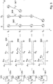
- cyclic measuring cycles are implemented in a level measuring device, this results in a sequence of received echo curves as shown in Fig. 2 is pictured. As an example, four independent measuring cycles are shown at intervals of 5 minutes each. Of course, significantly faster measurement cycles, for example at intervals of 1 second, can also be implemented.
- the scenario shown shows the conditions when filling a container 201.
- a measuring cycle of the level measuring device 101 is initiated.
- the course of the location of the echoes e0, e3, e6 and e8 caused by the antenna 104 itself is described by a common track T0.
- the course of the echoes e1 and e4 caused by the inflow pipe 106 is described by the associated track T1.
- the course of the echoes caused by the filling material 105 over several measurement cycles is described by the track T2, which consists of the echoes e2, e5, e7 and c9.
- tracks T0 and T2 are initialized at time t0 and continuously expanded at times t1, t2 and t3. Furthermore, track T1 is initialized at time t0 and expanded at time t1 as part of the signal processing procedure.
- the assignment of the currently recorded echoes of an echo curve to the tracks already recorded in earlier measurement cycles is essentially achieved by considering the differences in relation to the location and the amplitude of the track and the respective echo, and only assigning echoes to tracks, if they have approximately the same amplitude and position as the last known corresponding characteristic values of the tracks.
- Fig. 3 now illustrates the conditions when filling the same container with a liquid, which in contrast to the example Fig. 2 has a significantly lower DK value and thus a significantly lower reflectivity.
- the DK value describes the dielectric constant of a medium and is also called permittivity.
- the echo curves 301, 302, 303 and 304 recorded at times t0 to t3 differ from the corresponding echo curves in FIG Fig. 2 mainly in that the echoes c12, e15, e17 and e19 of the product reflection have a lower amplitude.
- a conventional tracking device 115 has to decide at time t t2 whether the echo e17 identified in the curve 303 should be assigned to the pre-existing track T3 305, T4 306 or T5 307. Due to the large difference in location between Track T3 and Echo e17, processing becomes more conventional Tracking procedure quickly made clear that the echo can only be assigned to track T4 or track T5.
- this step of "pre-selection” is also described as “gating”. Since the current amplitude values of the echo e14 (track T4) and the echo e15 (track T5) are almost identical, the decision to which track the echo e17 should be assigned to can only be made in the present case on the basis of the smallest spatial difference between the echo and the be tracked. As a result, the echo e17 and subsequently also the echo e19 are erroneously assigned to track T4.
- Fig. 4 shows an essential step in the evaluation of the tracks of a track list.
- the mobility of the tracks can be examined using known methods. For example, disclosures can be found in EP 2 366 983 A1 . In contrast to a classic movement analysis, which only makes statements about which track and / or which echo is moving, the analysis of mobility also allows statements about which track has a proven stationarity.
- the representation of the Fig. 4 illustrates this connection using the track list of Fig. 2 .
- tracks T0, T1 and T2 are initialized. Since all of these tracks only have a single echo, and in the present case no Doppler evaluation is to take place, no statement can be made as to the mobility of the tracks at the appropriate time.
- the mobility evaluation device 116 recognizes that the track T2 has moved between t0 and t1, whereas the track T0 has no movement in the same time period.
- the mobility M (T2) is consequently increased, whereas the mobility M (T0) is decreased.
- Fig. 5 once again illustrates the pre-selection of potential follow-up echoes of a track, also called gating, which takes place within the tracking device 115.
- a track gate or gate defines a position area in which potential follow-up echoes of a track must lie.
- a priori knowledge about the respective application flows into the definition of the width of a gate. For example, it can be determined that a level change may have a maximum filling or emptying speed of 0.1 m per second. In connection with a typical measurement repetition frequency of 1 second between two measurement cycles of the level measuring device, it can be concluded that a potential follow-up echo of a track is in a range of + - 10 cm around the previously registered location of the track must be. All echoes that are further away from the track are no longer considered successors for causal reasons.
- Fig. 5 shows an example of a tracking situation with drawn gates GT0, GT1, GT2 of the tracks T0, T1, T2. It becomes clear that the determination of potential successors of a track can be greatly accelerated. Furthermore, it also becomes apparent that an incorrect assignment - as in Fig. 3 shown - cannot be prevented by conventional gating, since when two tracks merge, the respective gates overlap, and it therefore depends on the amplitude conditions whether a correct assignment of echoes to tracks can be made or not.
- the invention provides a robust method for tracking various echoes.
- the present invention improves the improvement of known tracking algorithms when crossing two different tracks.
- Fig. 6 shows an echo signal processing unit 601 modified according to the invention, which differs from previously known units 108 by a modified tracking device 602.
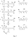
- Fig. 7 shows the sequence of a signal processing procedure with a modified signal processing unit 601.
- the illustration already shows that Fig. 3 known echo curve sequence 301, 302, 303, 304, which results in media with a poor DK value.
- the tracks T3 (305), T4 (306) and T5 (307) are off Fig. 3 Mobility values determined at times t0, t1, t2 and t3 are shown.
- track T3 (305) is initialized using echo e10.
- the tracks T4 (306) and T5 (307) are reinitialized with the echoes e11 and e12.
- the mobility evaluation device 116 initializes the mobility values of the three tracks to 0 (701), which means that nothing is said can be made about stationary behavior or movement. At this point in time, a tracking device according to the invention also defines gates G0, G1 and G2 as expected ranges for the continuation of the tracks.
- the tracks T3, T4 and T5 continue with the echoes e13, e14 and e15. Furthermore, a first statement about the mobility of the tracks can be made at this time.
- the associated mobility diagram 702 shows that track T3 and T4 show slightly stationary behavior, whereas track T5 moves. In other words, one can say that the echoes of the tracks T3, T4 or also the tracks T3, T4 have negative mobility values, whereas the echoes of the track T5 or the track T5 have a positive mobility value.
- the tracking device according to the invention now calculates the width of the new gates G3, G4 and G5 using the mobility values of the tracks. In the present exemplary embodiment, only the negative mobility is evaluated, which leads to the width of the gates G3 and G4 being reduced in comparison to the width of the gates G0 and G1. It may also be possible to use positive mobility to widen gates.
- the flow chart of Fig. 8 shows an example of a tracking according to an embodiment of the present invention.
- the method can be used in particular in a tracking device 602 according to the invention.
- the tracking method begins in the start state 801.
- step 802 the limits of the track gates are first determined, whereupon in step 803 the costs of assigning the respective echo to the track are calculated for those echoes which are in the region of the track gate of a track .
- the cost of an assignment is a measure of how well an echo fits a track.
- the costs can be calculated according to known methods, in particular large amplitude differences or large spatial differences can lead to high costs.
- WO2009 / 037000 describes corresponding procedures.
- an assignment suggestion for the continuation of the tracks with the respective echoes is preferably calculated using global cost minimization algorithms. Revelations can also be found in WO2009 / 037000 .
- the echoes are formally adopted in the track list. Steps 806 and 807 serve to reinitialize tracks with unassigned echoes or to delete tracks that can no longer be continued, for example after a correspondingly long time without assignment.
- the tracking process ends in step 808.
- the mobility values of the individual tracks are used to determine gates modified according to the invention for the tracks in step 802.
- Fig. 9 shows in detail the sequence for gating according to the present embodiment.
- step 8020 the first track in the track list is first selected. Using the mobility list provided by the mobility evaluation device 116, it is now checked in step 8022 whether the track is securely stationary, i.e. whether his mobility is identical -100%. If so, the update of the gates will be suspended and the next track will be taken directly. Otherwise, the new position of the gate is determined in step 8023, taking into account the parameterized or permanently programmed gate widths. In step 8024, it is checked whether the mobility value of the current track indicates at least stationary tendencies. If this is the case, the width of the gate is subsequently reduced according to the invention in step S025. When the gates of each track have been calculated, expiration ends in the final state 8028.
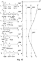
- Fig. 10 shows using the example of the curve sequence Fig. 3 the sequence of a tracking method according to the invention.
- Echo curves 1029, 1030, 1031, 1032 and 1001 first show the filling of the container 201. Due to the mobility of the track TC 1006, which is recognized with increasing certainty and the consequent stationarity of the tracks TA 1004 and TB 1005, 1007, the gates of the tracks TA and TB 1008, 1009, 1011, 1012, 1014, 1015, 1017, 1019, 1020, 1022, 1023, 1025, 1026, 1027 are continuously reduced in terms of their width, it being expedient not to fall below a predefinable minimum width.
- Figure 10 shows a further embodiment variant of a method according to the invention.
- the width or the variance of a gating function or an expectation function can be increased if two echoes (1033, 1034) fall below a predetermined minimum distance.
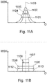
- Figure 11A shows two expectation functions 1101, 1102 according to an embodiment of the invention.
- the transverse axis 1110 here designates the distance to the filling material and the vertical axis 1111 designates the probability that an echo which has a specific distance from the level measuring device can be assigned to a specific track.
- the two expectation functions 1101 and 1102 are, for example, Gaussian and have different widths. So the flatter expectation function is 1101 wider (see arrow 1104) than the somewhat steeper expectation function 1102 (see arrow 1105).
- the width of the expectation function z For example, use the value that represents the width of the function at half height.
- Figure 11B shows two rectangular expectation functions 1106, 1107, also called window functions.
- width of the function is to be equated with the distance of the rising left leg 1112 to the falling right leg 1113.
- the rectangular expectation functions 1106, 1107 can be used, for example, to carry out a classic or an inventive gating method.
- expectation functions 1101, 1102 can be used, for example, to modify a method according to the invention for determining the cost of assigning echoes to tracks.
Landscapes
- Physics & Mathematics (AREA)
- Engineering & Computer Science (AREA)
- Remote Sensing (AREA)
- Radar, Positioning & Navigation (AREA)
- General Physics & Mathematics (AREA)
- Computer Networks & Wireless Communication (AREA)
- Fluid Mechanics (AREA)
- Thermal Sciences (AREA)
- Electromagnetism (AREA)
- Measurement Of Velocity Or Position Using Acoustic Or Ultrasonic Waves (AREA)
- Radar Systems Or Details Thereof (AREA)
- Investigating Or Analyzing Materials By The Use Of Ultrasonic Waves (AREA)
- Measurement Of Levels Of Liquids Or Fluent Solid Materials (AREA)
Claims (10)
- Appareil de mesure de niveau de remplissage (101) destiné à déterminer des valeurs de mobilité d'échos d'une courbe d'échos et à exécuter un procédé de suivi en fonction d'au moins une des valeurs de mobilité, une valeur de mobilité d'un écho étant une valeur caractéristique pour le déplacement de l'écho, qui est déterminée en tenant compte de déplacements s'effectuant simultanément ou d'une autre modification d'au moins un autre écho, l'appareil de mesure de niveau de remplissage comportant :une unité de calcul (108) destinée à déterminer une première valeur de mobilité d'un premier écho d'une première courbe d'échos en tenant compte d'un décalage de position du premier écho et d'un décalage de position d'un autre écho de la première courbe d'échos ;l'unité de calcul (108) étant en outre conçue pour exécuter un procédé de suivi pour le groupement d'échos de courbes d'échos successives dans le temps, qui sont à attribuer à des points de réflexion identiques ;l'unité de calcul (108) associant un second écho d'une seconde courbe d'échos détectée après la première courbe d'échos à une piste de suivi donnée, en tenant compte au moins de la première valeur de mobilité ;l'association du second écho à la piste de suivi donnée étant effectuée au moyen d'une fonction d'espérance, avec laquelle une probabilité de l'association correcte du second écho à la piste de suivi donnée peut être calculée ;une largeur ou une variance de la fonction d'espérance étant réduite si le décalage de position du premier écho de la première courbe d'échos est nul, mais que le décalage de position de l'autre écho de la première courbe d'échos n'est pas nul ; etla largeur ou la variance de la fonction d'espérance étant augmentée si le décalage de position du premier écho de la première courbe d'échos n'est pas nul.
- Appareil de mesure de niveau de remplissage selon la revendication 1,
dans lequel la fonction d'espérance est un fenêtrage. - Appareil de mesure de niveau de remplissage selon l'une des revendications précédentes,
dans lequel la largeur ou la variance de la fonction d'espérance est augmentée si le second écho passe en dessous d'une distance minimale par rapport à un écho voisin de la seconde courbe d'échos. - Appareil de mesure de niveau de remplissage selon la revendication 3,
dans lequel la largeur ou la variance de la fonction d'espérance est augmentée si la fonction d'espérance se chevauche avec une fonction d'espérance correspondante de l'écho voisin. - Appareil de mesure de niveau de remplissage selon l'une des revendications précédentes,
dans lequel une valeur de mobilité du second écho est réduite si le décalage de position du premier écho de la première courbe d'échos est nul, mais que le décalage de position de l'autre écho de la première courbe d'échos n'est pas nul. - Appareil de mesure de niveau de remplissage selon l'une des revendications précédentes, dans lequel
les fonctions d'espérance, qui sont associées aux échos d'une courbe d'échos initiale, qui a été détectée au début du procédé de suivi et dont l'utilisation permet de constater si un écho d'une courbe d'échos détectée ultérieurement est à associer à une piste de suivi donnée, présentent des largeurs ou variances identiques. - Utilisation d'un appareil de mesure de niveau de remplissage selon l'une des revendications précédentes pour la mesure d'interface.
- Procédé destiné à déterminer des valeurs de mobilité d'échos d'une courbe d'échos et à exécuter un procédé de suivi en fonction d'au moins une des valeurs de mobilité, une valeur de mobilité d'un écho étant une valeur caractéristique pour le déplacement de l'écho, qui est déterminée en tenant compte de déplacements s'effectuant simultanément ou d'une autre modification d'au moins un autre écho, le procédé comportant les étapes de :détermination d'une première valeur de mobilité d'un premier écho d'une première courbe d'échos en tenant compte d'un décalage de position du premier écho et d'un décalage de position d'un autre écho de la première courbe d'échos ;exécution d'un procédé de suivi pour le groupement d'échos de courbes d'échos successives dans le temps, qui sont à attribuer à des points de réflexion identiques ;association d'un second écho d'une seconde courbe d'échos détectée après la première courbe d'échos à une piste de suivi donnée, en tenant compte au moins de la première valeur de mobilité ;l'association du second écho à la piste de suivi donnée étant effectuée au moyen d'une fonction d'espérance, avec laquelle une probabilité de l'association correcte du second écho à la piste de suivi donnée peut être calculée ;une largeur ou une variance de la fonction d'espérance étant réduite si le décalage de position du premier écho de la première courbe d'échos est nul, mais que le décalage de position de l'autre écho de la première courbe d'échos n'est pas nul ; etla largeur ou la variance de la fonction d'espérance étant augmentée si le décalage de position du premier écho de la première courbe d'échos n'est pas nul.
- Élément de programme qui, lorsqu'il est exécuté sur un processeur d'un appareil de mesure de niveau de remplissage, amène le processeur à exécuter le procédé selon la revendication 8.
- Support lisible par ordinateur sur lequel est enregistré un élément de programme qui, lorsqu'il est exécuté sur un processeur d'un appareil de mesure de niveau de remplissage, amène le processeur à exécuter le procédé selon la revendication 8.
Priority Applications (17)
| Application Number | Priority Date | Filing Date | Title |
|---|---|---|---|
| EP11176609.3A EP2554956B1 (fr) | 2011-08-04 | 2011-08-04 | Suivi en fonction de la mobilité |
| US13/552,189 US9086310B2 (en) | 2011-08-04 | 2012-07-18 | Tracking with consideration of mobility |
| EP12740161.0A EP2739945B1 (fr) | 2011-08-04 | 2012-07-26 | Appareil de mesure du niveau de remplissage et procédé de détermination d'un rapport fonctionnel entre différentes pistes |
| PCT/EP2012/064742 WO2013017534A1 (fr) | 2011-08-04 | 2012-07-26 | Rapport linéaire entre suivis |
| CN201280038550.1A CN103733033B (zh) | 2011-08-04 | 2012-07-26 | 轨迹之间的线性关系 |
| AU2012292175A AU2012292175B2 (en) | 2011-08-04 | 2012-07-26 | Linear relationship between tracks |
| BR112014001164-8A BR112014001164A2 (pt) | 2011-08-04 | 2012-07-26 | rastreamento, levando em consideração uma relação linear |
| CN201280038603.XA CN103748440B (zh) | 2011-08-04 | 2012-07-26 | 在考虑线性关系的情况下进行追踪 |
| RU2014108062A RU2606456C2 (ru) | 2011-08-04 | 2012-07-26 | Линейное отношение между треками |
| BR112014001545-7A BR112014001545A2 (pt) | 2011-08-04 | 2012-07-26 | relação linear entre pistas |
| HUE12740162A HUE044041T2 (hu) | 2011-08-04 | 2012-07-26 | Lineáris kapcsolat pályák között |
| EP12740162.8A EP2739946B1 (fr) | 2011-08-04 | 2012-07-26 | Relation lineaire entre pistes |
| AU2012292174A AU2012292174B2 (en) | 2011-08-04 | 2012-07-26 | Tracking process taking into consideration a linear relationship |
| PCT/EP2012/064740 WO2013017533A1 (fr) | 2011-08-04 | 2012-07-26 | Suivi prenant en considération un rapport linéaire |
| CN201210274123.5A CN102914346B (zh) | 2011-08-04 | 2012-08-02 | 在考虑移动性的情况下的跟踪 |
| RU2012133315/28A RU2600496C2 (ru) | 2011-08-04 | 2012-08-03 | Отслеживание с учетом изменчивости |
| BR102012019557A BR102012019557A2 (pt) | 2011-08-04 | 2012-08-03 | Rastreamento com a consideração de mobilidade |
Applications Claiming Priority (1)
| Application Number | Priority Date | Filing Date | Title |
|---|---|---|---|
| EP11176609.3A EP2554956B1 (fr) | 2011-08-04 | 2011-08-04 | Suivi en fonction de la mobilité |
Publications (2)
| Publication Number | Publication Date |
|---|---|
| EP2554956A1 EP2554956A1 (fr) | 2013-02-06 |
| EP2554956B1 true EP2554956B1 (fr) | 2020-07-29 |
Family
ID=44674223
Family Applications (1)
| Application Number | Title | Priority Date | Filing Date |
|---|---|---|---|
| EP11176609.3A Active EP2554956B1 (fr) | 2011-08-04 | 2011-08-04 | Suivi en fonction de la mobilité |
Country Status (5)
| Country | Link |
|---|---|
| US (1) | US9086310B2 (fr) |
| EP (1) | EP2554956B1 (fr) |
| CN (1) | CN102914346B (fr) |
| BR (1) | BR102012019557A2 (fr) |
| RU (1) | RU2600496C2 (fr) |
Families Citing this family (11)
| Publication number | Priority date | Publication date | Assignee | Title |
|---|---|---|---|---|
| EP2584324B1 (fr) * | 2011-10-17 | 2018-09-19 | VEGA Grieshaber KG | Appareil de mesure du niveau de remplissage et procédé de détermination d'un rapport fonctionnel entre différentes pistes |
| DE102013213040B4 (de) * | 2013-07-03 | 2019-07-04 | Vega Grieshaber Kg | Übertragungsvorrichtung für ein Messgerät und Verfahren zum Übertragen von Rohdaten mit einer Übertragungsvorrichtung |
| EP2869042B1 (fr) * | 2013-11-04 | 2016-08-10 | VEGA Grieshaber KG | Suppression du bruit basée sur un modèle pour des appareils de mesure du niveau de remplissage |
| US9778089B2 (en) * | 2014-06-30 | 2017-10-03 | Rosemount Tank Radar Ab | Multi-channel guided wave radar level gauge |
| US9618612B2 (en) * | 2015-02-13 | 2017-04-11 | Honeywell International Inc. | Marking tank obstructions using an electronic level gauge |
| EP3112821B1 (fr) * | 2015-07-02 | 2018-05-02 | VEGA Grieshaber KG | Procede et appareil de mesure de niveau de remplissage |
| DE102016100674B4 (de) * | 2016-01-15 | 2019-03-21 | Krohne Messtechnik Gmbh | Verfahren zum Betreiben eines berührungslos arbeitenden Ultraschall- oder Radar-Füllstandmessgeräts und berührungslos arbeitendes Ultraschall- oder Radar-Füllstandmessgerät |
| JP6750567B2 (ja) * | 2017-05-30 | 2020-09-02 | 株式会社Soken | 物体検出装置 |
| EP3575817A1 (fr) * | 2018-05-30 | 2019-12-04 | VEGA Grieshaber KG | Procédé de mesure de remplissage |
| US11454716B2 (en) * | 2019-12-30 | 2022-09-27 | Woven Planet North America, Inc. | Systems and methods for adaptive gating in initialization of radar tracking |
| CN113108868A (zh) * | 2021-04-19 | 2021-07-13 | 南宁师范大学 | 一种基于主波峰的自适应波形重跟踪算法 |
Family Cites Families (24)
| Publication number | Priority date | Publication date | Assignee | Title |
|---|---|---|---|---|
| DE3337690A1 (de) | 1983-10-17 | 1985-04-25 | VEGA Grieshaber GmbH & Co, 7620 Wolfach | Verfahren und vorrichtung zur messung des fuellstands in einem behaelter mittels schall-/ultraschallwellen |
| US4992998A (en) * | 1986-10-03 | 1991-02-12 | Federal Industries Industrial Group Inc. | Acoustic range finding system |
| US5157639A (en) * | 1990-09-04 | 1992-10-20 | Magnetrol International | Ultrasonic detector |
| DE4234300C2 (de) | 1992-10-12 | 1998-11-26 | Grieshaber Vega Kg | Füllstand-Meßverfahren |
| JPH1164072A (ja) * | 1997-08-20 | 1999-03-05 | Kaijo Corp | 界面レベル計 |
| US5973637A (en) * | 1998-01-09 | 1999-10-26 | Endress + Hauser Gmbh + Co. | Partial probe mapping |
| US6504793B2 (en) * | 2000-09-11 | 2003-01-07 | Vega Grieshaber Kg | Method and device for range measurement |
| US6634228B2 (en) * | 2001-01-26 | 2003-10-21 | Endress + Hauser Gmbh + Co. Kg | Method of measuring level in a vessel |
| US6684919B2 (en) * | 2001-02-08 | 2004-02-03 | Vega Grieshaber Kg | Filling level measuring device and method for the non-contact determination of the filling level of a filling product in a receptacle |
| AU2003250981B2 (en) * | 2002-07-19 | 2009-05-28 | Vega Grieshaber Kg | Method and device for determining an expectancy range for a level echo and a spurious echo |
| SE0202491D0 (sv) * | 2002-08-22 | 2002-08-22 | Saab Marine Electronics | System for level gauging and alarms |
| US6759976B1 (en) * | 2002-12-20 | 2004-07-06 | Saab Marine Electronics Ab | Method and apparatus for radar-based level gauging |
| DE10260962A1 (de) * | 2002-12-20 | 2004-07-01 | Endress + Hauser Gmbh + Co. Kg | Füllstandsmeßgerät und Verfahren zur Füllstandsmessung nach dem Laufzeitprinzip |
| DE10325267A1 (de) | 2003-06-03 | 2004-12-23 | Endress + Hauser Gmbh + Co. Kg | Anordnung und Verfahren zur Füllstandsmessung |
| US7333900B2 (en) * | 2004-08-16 | 2008-02-19 | Vega Grieshaber Kg | Automatic parasitic echo storage |
| DE102004052110B4 (de) * | 2004-10-26 | 2018-08-23 | Endress+Hauser SE+Co. KG | Verfahren zur Füllstandsmessung nach dem Laufzeitprinzip |
| SE0403165D0 (sv) * | 2004-12-23 | 2004-12-23 | Saab Rosemount Tank Radar Ab | A radar level gauge system |
| US7355548B2 (en) * | 2005-09-01 | 2008-04-08 | Rosemount Tank Radar Ab | Processing of tank signal in radar level gauge system |
| US7467548B2 (en) * | 2005-10-14 | 2008-12-23 | Rosemount Tank Radar Ab | Radar level gauge system and coupling |
| DE102007031261A1 (de) | 2007-07-05 | 2009-01-08 | Universtität Regensburg | Lumineszierende Metallkomplexe mit sperrigen Hilfsliganden |
| EP2128576B1 (fr) * | 2008-05-27 | 2016-12-28 | VEGA Grieshaber KG | Procédé de détection de double parole basé sur les propriétés acoustiques spectrales |
| ATE528662T1 (de) | 2008-07-22 | 2011-10-15 | Siemens Milltronics Proc Instr | Verarbeitung von impulsecho-messsignalen |
| EP2226615B1 (fr) * | 2009-03-02 | 2018-08-22 | VEGA Grieshaber KG | Mesures de niveaux de remplissage à l'aide d'une évaluation d'une courbe d'écho |
| EP2366983B1 (fr) * | 2010-03-17 | 2020-04-29 | VEGA Grieshaber KG | Reconnaissance de mobilité dans un appareil de mesure de niveau |
-
2011
- 2011-08-04 EP EP11176609.3A patent/EP2554956B1/fr active Active
-
2012
- 2012-07-18 US US13/552,189 patent/US9086310B2/en active Active
- 2012-08-02 CN CN201210274123.5A patent/CN102914346B/zh active Active
- 2012-08-03 RU RU2012133315/28A patent/RU2600496C2/ru active
- 2012-08-03 BR BR102012019557A patent/BR102012019557A2/pt not_active Application Discontinuation
Non-Patent Citations (1)
| Title |
|---|
| None * |
Also Published As
| Publication number | Publication date |
|---|---|
| EP2554956A1 (fr) | 2013-02-06 |
| CN102914346A (zh) | 2013-02-06 |
| US9086310B2 (en) | 2015-07-21 |
| CN102914346B (zh) | 2016-10-12 |
| RU2600496C2 (ru) | 2016-10-20 |
| US20130035880A1 (en) | 2013-02-07 |
| BR102012019557A2 (pt) | 2014-02-18 |
| RU2012133315A (ru) | 2014-02-10 |
Similar Documents
| Publication | Publication Date | Title |
|---|---|---|
| EP2554956B1 (fr) | Suivi en fonction de la mobilité | |
| EP2366983B1 (fr) | Reconnaissance de mobilité dans un appareil de mesure de niveau | |
| DE69621154T2 (de) | Verfolgungsverfahren für radarsystem | |
| EP2667219B1 (fr) | Détection d'objets radar avec un capteur radar d'un véhicule automobile | |
| EP2372318B1 (fr) | Accumulation d'écho parasite dans des bruits de récipients | |
| EP2365302B1 (fr) | Mesure de la distance par rapport à, au moins, une première surface limite | |
| WO2008080840A1 (fr) | Procédé pour déterminer et surveiller le niveau d'un fluide dans un récipient selon un procédé de mesure du temps de propagation | |
| DE102018207744B3 (de) | Radar-Signalverarbeitungsvorrichtung | |
| EP3025128B1 (fr) | Procédé pour déterminer et surveiller le niveau d'un fluide dans un récipient selon un procédé de mesure du temps de propagation | |
| DE102010034263A1 (de) | Verfahren zur Erzeugung einer Schwellwertkurve sowie Verfahren zur Auswertung von Signalen eines Ultraschallsensors und Vorrichtung zur Umfelderfassung | |
| DE102016218093A1 (de) | Betriebsverfahren für ein Ultraschallsensorsystem, Steuereinrichtung, Ultraschallsensorsystem und Fahrzeug | |
| EP2309235A1 (fr) | Traitement de signal à base de segments | |
| DE102012020413B4 (de) | Verfahren und Vorrichtung zur Umfelderfassung | |
| EP2584324B1 (fr) | Appareil de mesure du niveau de remplissage et procédé de détermination d'un rapport fonctionnel entre différentes pistes | |
| EP2739946B1 (fr) | Relation lineaire entre pistes | |
| EP2182380B1 (fr) | Procédé de détection de la superposition de pointe dans un spectre discret d'un signal de repérage | |
| DE102014215858A1 (de) | Verfahren und Vorrichtung zur Detektion von sich zwischen seitlich an einem Fahrbahnrand angeordneten Objekten erstreckenden Parklücken | |
| WO2018153892A1 (fr) | Procédé et dispositif de fourniture d'informations de signaux ultrasonores | |
| DE10238896B4 (de) | Verfahren zur Auswertung von Radardaten | |
| WO2024184223A1 (fr) | Procédé mis en œuvre par ordinateur pour l'apprentissage automatique de débruitage de données dans un processus de traitement de données radar, procédé de traitement de données radar, programme informatique pour traitement de données radar, capteur radar pour la détection d'environnement pour un véhicule | |
| EP1742085B1 (fr) | Procédé destiné à la recherche d'objets dans des systèmes radar pour véhicules | |
| WO2020201337A1 (fr) | Détermination d'une vitesse relative univoque au moyen d'une adaptation de modèle | |
| EP4439118B1 (fr) | Procédé de fonctionnement d'un capteur radar destiné à la télémétrie et capteur radar correspondant | |
| DE102017123901B4 (de) | Verfahren zum Erfassen von Umgebungsinformationen | |
| DE102023123375A1 (de) | Kompensation von Interferenzen durch saisonale Zeitreihendekomposition in Radarsystemen |
Legal Events
| Date | Code | Title | Description |
|---|---|---|---|
| PUAI | Public reference made under article 153(3) epc to a published international application that has entered the european phase |
Free format text: ORIGINAL CODE: 0009012 |
|
| AK | Designated contracting states |
Kind code of ref document: A1 Designated state(s): AL AT BE BG CH CY CZ DE DK EE ES FI FR GB GR HR HU IE IS IT LI LT LU LV MC MK MT NL NO PL PT RO RS SE SI SK SM TR |
|
| AX | Request for extension of the european patent |
Extension state: BA ME |
|
| 17P | Request for examination filed |
Effective date: 20130703 |
|
| RBV | Designated contracting states (corrected) |
Designated state(s): AL AT BE BG CH CY CZ DE DK EE ES FI FR GB GR HR HU IE IS IT LI LT LU LV MC MK MT NL NO PL PT RO RS SE SI SK SM TR |
|
| STAA | Information on the status of an ep patent application or granted ep patent |
Free format text: STATUS: EXAMINATION IS IN PROGRESS |
|
| 17Q | First examination report despatched |
Effective date: 20181203 |
|
| GRAP | Despatch of communication of intention to grant a patent |
Free format text: ORIGINAL CODE: EPIDOSNIGR1 |
|
| STAA | Information on the status of an ep patent application or granted ep patent |
Free format text: STATUS: GRANT OF PATENT IS INTENDED |
|
| RIC1 | Information provided on ipc code assigned before grant |
Ipc: G01S 13/88 20060101ALN20200127BHEP Ipc: G01F 23/28 20060101AFI20200127BHEP Ipc: G01S 13/70 20060101ALI20200127BHEP Ipc: G01S 7/41 20060101ALI20200127BHEP |
|
| RIC1 | Information provided on ipc code assigned before grant |
Ipc: G01S 13/88 20060101ALN20200205BHEP Ipc: G01S 7/41 20060101ALI20200205BHEP Ipc: G01F 23/28 20060101AFI20200205BHEP Ipc: G01S 13/70 20060101ALI20200205BHEP |
|
| INTG | Intention to grant announced |
Effective date: 20200227 |
|
| GRAS | Grant fee paid |
Free format text: ORIGINAL CODE: EPIDOSNIGR3 |
|
| GRAA | (expected) grant |
Free format text: ORIGINAL CODE: 0009210 |
|
| STAA | Information on the status of an ep patent application or granted ep patent |
Free format text: STATUS: THE PATENT HAS BEEN GRANTED |
|
| AK | Designated contracting states |
Kind code of ref document: B1 Designated state(s): AL AT BE BG CH CY CZ DE DK EE ES FI FR GB GR HR HU IE IS IT LI LT LU LV MC MK MT NL NO PL PT RO RS SE SI SK SM TR |
|
| REG | Reference to a national code |
Ref country code: GB Ref legal event code: FG4D Free format text: NOT ENGLISH |
|
| REG | Reference to a national code |
Ref country code: CH Ref legal event code: EP |
|
| REG | Reference to a national code |
Ref country code: AT Ref legal event code: REF Ref document number: 1296331 Country of ref document: AT Kind code of ref document: T Effective date: 20200815 |
|
| REG | Reference to a national code |
Ref country code: IE Ref legal event code: FG4D Free format text: LANGUAGE OF EP DOCUMENT: GERMAN |
|
| REG | Reference to a national code |
Ref country code: DE Ref legal event code: R096 Ref document number: 502011016822 Country of ref document: DE |
|
| REG | Reference to a national code |
Ref country code: LT Ref legal event code: MG4D |
|
| REG | Reference to a national code |
Ref country code: NL Ref legal event code: MP Effective date: 20200729 |
|
| PG25 | Lapsed in a contracting state [announced via postgrant information from national office to epo] |
Ref country code: GR Free format text: LAPSE BECAUSE OF FAILURE TO SUBMIT A TRANSLATION OF THE DESCRIPTION OR TO PAY THE FEE WITHIN THE PRESCRIBED TIME-LIMIT Effective date: 20201030 Ref country code: LT Free format text: LAPSE BECAUSE OF FAILURE TO SUBMIT A TRANSLATION OF THE DESCRIPTION OR TO PAY THE FEE WITHIN THE PRESCRIBED TIME-LIMIT Effective date: 20200729 Ref country code: HR Free format text: LAPSE BECAUSE OF FAILURE TO SUBMIT A TRANSLATION OF THE DESCRIPTION OR TO PAY THE FEE WITHIN THE PRESCRIBED TIME-LIMIT Effective date: 20200729 Ref country code: BG Free format text: LAPSE BECAUSE OF FAILURE TO SUBMIT A TRANSLATION OF THE DESCRIPTION OR TO PAY THE FEE WITHIN THE PRESCRIBED TIME-LIMIT Effective date: 20201029 Ref country code: ES Free format text: LAPSE BECAUSE OF FAILURE TO SUBMIT A TRANSLATION OF THE DESCRIPTION OR TO PAY THE FEE WITHIN THE PRESCRIBED TIME-LIMIT Effective date: 20200729 Ref country code: NO Free format text: LAPSE BECAUSE OF FAILURE TO SUBMIT A TRANSLATION OF THE DESCRIPTION OR TO PAY THE FEE WITHIN THE PRESCRIBED TIME-LIMIT Effective date: 20201029 Ref country code: SE Free format text: LAPSE BECAUSE OF FAILURE TO SUBMIT A TRANSLATION OF THE DESCRIPTION OR TO PAY THE FEE WITHIN THE PRESCRIBED TIME-LIMIT Effective date: 20200729 Ref country code: PT Free format text: LAPSE BECAUSE OF FAILURE TO SUBMIT A TRANSLATION OF THE DESCRIPTION OR TO PAY THE FEE WITHIN THE PRESCRIBED TIME-LIMIT Effective date: 20201130 Ref country code: FI Free format text: LAPSE BECAUSE OF FAILURE TO SUBMIT A TRANSLATION OF THE DESCRIPTION OR TO PAY THE FEE WITHIN THE PRESCRIBED TIME-LIMIT Effective date: 20200729 |
|
| PG25 | Lapsed in a contracting state [announced via postgrant information from national office to epo] |
Ref country code: PL Free format text: LAPSE BECAUSE OF FAILURE TO SUBMIT A TRANSLATION OF THE DESCRIPTION OR TO PAY THE FEE WITHIN THE PRESCRIBED TIME-LIMIT Effective date: 20200729 Ref country code: LV Free format text: LAPSE BECAUSE OF FAILURE TO SUBMIT A TRANSLATION OF THE DESCRIPTION OR TO PAY THE FEE WITHIN THE PRESCRIBED TIME-LIMIT Effective date: 20200729 Ref country code: RS Free format text: LAPSE BECAUSE OF FAILURE TO SUBMIT A TRANSLATION OF THE DESCRIPTION OR TO PAY THE FEE WITHIN THE PRESCRIBED TIME-LIMIT Effective date: 20200729 Ref country code: IS Free format text: LAPSE BECAUSE OF FAILURE TO SUBMIT A TRANSLATION OF THE DESCRIPTION OR TO PAY THE FEE WITHIN THE PRESCRIBED TIME-LIMIT Effective date: 20201129 |
|
| PG25 | Lapsed in a contracting state [announced via postgrant information from national office to epo] |
Ref country code: NL Free format text: LAPSE BECAUSE OF FAILURE TO SUBMIT A TRANSLATION OF THE DESCRIPTION OR TO PAY THE FEE WITHIN THE PRESCRIBED TIME-LIMIT Effective date: 20200729 |
|
| REG | Reference to a national code |
Ref country code: CH Ref legal event code: PL |
|
| PG25 | Lapsed in a contracting state [announced via postgrant information from national office to epo] |
Ref country code: LI Free format text: LAPSE BECAUSE OF NON-PAYMENT OF DUE FEES Effective date: 20200831 Ref country code: IT Free format text: LAPSE BECAUSE OF FAILURE TO SUBMIT A TRANSLATION OF THE DESCRIPTION OR TO PAY THE FEE WITHIN THE PRESCRIBED TIME-LIMIT Effective date: 20200729 Ref country code: CZ Free format text: LAPSE BECAUSE OF FAILURE TO SUBMIT A TRANSLATION OF THE DESCRIPTION OR TO PAY THE FEE WITHIN THE PRESCRIBED TIME-LIMIT Effective date: 20200729 Ref country code: EE Free format text: LAPSE BECAUSE OF FAILURE TO SUBMIT A TRANSLATION OF THE DESCRIPTION OR TO PAY THE FEE WITHIN THE PRESCRIBED TIME-LIMIT Effective date: 20200729 Ref country code: DK Free format text: LAPSE BECAUSE OF FAILURE TO SUBMIT A TRANSLATION OF THE DESCRIPTION OR TO PAY THE FEE WITHIN THE PRESCRIBED TIME-LIMIT Effective date: 20200729 Ref country code: CH Free format text: LAPSE BECAUSE OF NON-PAYMENT OF DUE FEES Effective date: 20200831 Ref country code: MC Free format text: LAPSE BECAUSE OF FAILURE TO SUBMIT A TRANSLATION OF THE DESCRIPTION OR TO PAY THE FEE WITHIN THE PRESCRIBED TIME-LIMIT Effective date: 20200729 Ref country code: LU Free format text: LAPSE BECAUSE OF NON-PAYMENT OF DUE FEES Effective date: 20200804 Ref country code: RO Free format text: LAPSE BECAUSE OF FAILURE TO SUBMIT A TRANSLATION OF THE DESCRIPTION OR TO PAY THE FEE WITHIN THE PRESCRIBED TIME-LIMIT Effective date: 20200729 Ref country code: SM Free format text: LAPSE BECAUSE OF FAILURE TO SUBMIT A TRANSLATION OF THE DESCRIPTION OR TO PAY THE FEE WITHIN THE PRESCRIBED TIME-LIMIT Effective date: 20200729 |
|
| REG | Reference to a national code |
Ref country code: DE Ref legal event code: R097 Ref document number: 502011016822 Country of ref document: DE |
|
| REG | Reference to a national code |
Ref country code: BE Ref legal event code: MM Effective date: 20200831 |
|
| PG25 | Lapsed in a contracting state [announced via postgrant information from national office to epo] |
Ref country code: AL Free format text: LAPSE BECAUSE OF FAILURE TO SUBMIT A TRANSLATION OF THE DESCRIPTION OR TO PAY THE FEE WITHIN THE PRESCRIBED TIME-LIMIT Effective date: 20200729 |
|
| PLBE | No opposition filed within time limit |
Free format text: ORIGINAL CODE: 0009261 |
|
| STAA | Information on the status of an ep patent application or granted ep patent |
Free format text: STATUS: NO OPPOSITION FILED WITHIN TIME LIMIT |
|
| PG25 | Lapsed in a contracting state [announced via postgrant information from national office to epo] |
Ref country code: SK Free format text: LAPSE BECAUSE OF FAILURE TO SUBMIT A TRANSLATION OF THE DESCRIPTION OR TO PAY THE FEE WITHIN THE PRESCRIBED TIME-LIMIT Effective date: 20200729 |
|
| 26N | No opposition filed |
Effective date: 20210430 |
|
| PG25 | Lapsed in a contracting state [announced via postgrant information from national office to epo] |
Ref country code: FR Free format text: LAPSE BECAUSE OF NON-PAYMENT OF DUE FEES Effective date: 20200929 |
|
| PG25 | Lapsed in a contracting state [announced via postgrant information from national office to epo] |
Ref country code: SI Free format text: LAPSE BECAUSE OF FAILURE TO SUBMIT A TRANSLATION OF THE DESCRIPTION OR TO PAY THE FEE WITHIN THE PRESCRIBED TIME-LIMIT Effective date: 20200729 Ref country code: IE Free format text: LAPSE BECAUSE OF NON-PAYMENT OF DUE FEES Effective date: 20200804 Ref country code: BE Free format text: LAPSE BECAUSE OF NON-PAYMENT OF DUE FEES Effective date: 20200831 |
|
| REG | Reference to a national code |
Ref country code: AT Ref legal event code: MM01 Ref document number: 1296331 Country of ref document: AT Kind code of ref document: T Effective date: 20200804 |
|
| PG25 | Lapsed in a contracting state [announced via postgrant information from national office to epo] |
Ref country code: AT Free format text: LAPSE BECAUSE OF NON-PAYMENT OF DUE FEES Effective date: 20200804 |
|
| PG25 | Lapsed in a contracting state [announced via postgrant information from national office to epo] |
Ref country code: TR Free format text: LAPSE BECAUSE OF FAILURE TO SUBMIT A TRANSLATION OF THE DESCRIPTION OR TO PAY THE FEE WITHIN THE PRESCRIBED TIME-LIMIT Effective date: 20200729 Ref country code: MT Free format text: LAPSE BECAUSE OF FAILURE TO SUBMIT A TRANSLATION OF THE DESCRIPTION OR TO PAY THE FEE WITHIN THE PRESCRIBED TIME-LIMIT Effective date: 20200729 Ref country code: CY Free format text: LAPSE BECAUSE OF FAILURE TO SUBMIT A TRANSLATION OF THE DESCRIPTION OR TO PAY THE FEE WITHIN THE PRESCRIBED TIME-LIMIT Effective date: 20200729 |
|
| PG25 | Lapsed in a contracting state [announced via postgrant information from national office to epo] |
Ref country code: MK Free format text: LAPSE BECAUSE OF FAILURE TO SUBMIT A TRANSLATION OF THE DESCRIPTION OR TO PAY THE FEE WITHIN THE PRESCRIBED TIME-LIMIT Effective date: 20200729 |
|
| P01 | Opt-out of the competence of the unified patent court (upc) registered |
Effective date: 20230525 |
|
| PGFP | Annual fee paid to national office [announced via postgrant information from national office to epo] |
Ref country code: DE Payment date: 20250819 Year of fee payment: 15 |
|
| PGFP | Annual fee paid to national office [announced via postgrant information from national office to epo] |
Ref country code: GB Payment date: 20250818 Year of fee payment: 15 |